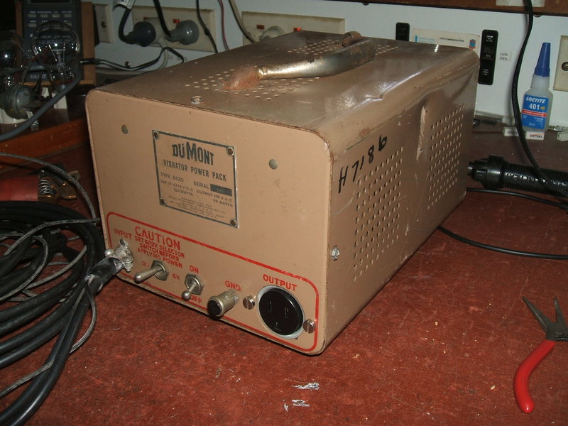
The dents suggest it's had a bit of use.
The dents suggest it's had a bit of use.
This DuMont inverter was bought at the
Blacktown Markets (a Sunday market at the drive in cinema car park, at
Blacktown in western Sydney) in the early 2000's. How and why it got into
Australia is a bit of a mystery, because there would be little use for
a 115V inverter here. Interestingly, the original output socket had been
replaced with the local 240V type which suggests that it had actually been
used locally. However, why it had been changed seems odd, and besides,
putting a 240V plug onto a 115V appliance is not a good thing to do for
obvious reasons.
It can only be assumed it was for some
specialised application.
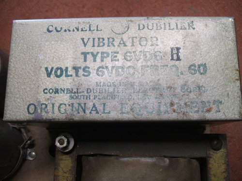
The specifications are interesting. It
accepts 6 or 12V input and provides a rated 75W output. The strange thing
is the transformer core looks like it could easily handle 150W, and the
vibrator is a large eight contact unit which should be good for at least
100W, perhaps 120W.
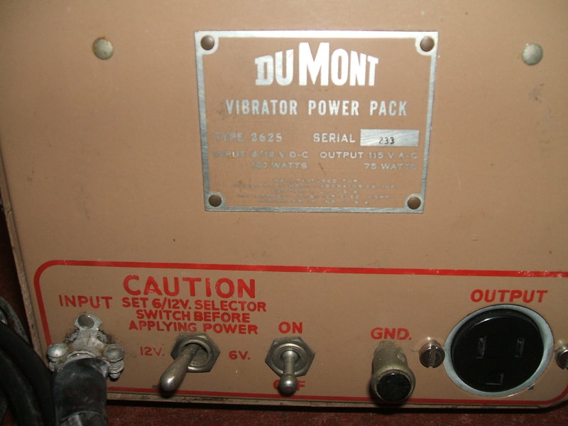
Input power is shown as 120W. Against an output power of 75W, this suggests an efficiency of only 62%.
Circuit.
The circuit is standard for this kind
of inverter. It uses a multi contact vibrator, transformer, and buffer
condenser in the normal way.
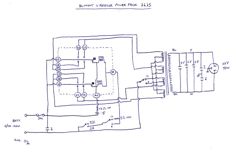
The A and B numbering on the vibrator pins refers to the two six
pin sockets.
As can be seen, the inverter can be used
on either 6 or 12V by changing the transformer primary tappings. The vibrator
drive coil is rated for 6V, so for 12V use a 5R resistor is introduced
in series.
Rather than switch the full battery current
to turn the inverter on or off, only the vibrator drive coil is switched
(yet another advantage of series drive). The power switch can therefore
be of low power. In the off position, the moving contacts are resting midway
between the fixed contacts so the inverter draws no power.
In my opinion, the fuse is grossly overrated.
At 30A it would only protect from sticking vibrator contacts or an extreme
overload like a 1KW radiator. 30A at 12V is 360W, and at 6V it's 180W.
Two spare fuses are kept inside the case.
Buffer capacitance.
The buffer capacitance consists mainly
of three oil filled paper condensers. No value was marked on them, only
a part number. I measured one to find it's value 3.5uF; a likely value
given the application and size. These three in parallel gives 10.5uF. Additionally,
are the two series 2uF condensers across the output socket for RF filtering.
In total, the buffer capacitance is therefore 11.5uF.
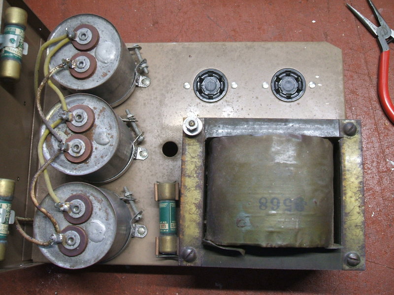
Top of chassis shows the three buffer condensers. The two six pin
sockets carry the vibrator.
Compared to a car radio power supply, 11.5uF
is a very high value.
There are two schools of thought when
it comes to selecting buffer capacitors for DC-AC inverters. The first
is to select it in the usual way as would be done with a car radio. That
is, to obtain the optimum waveform with the output unloaded. In the case
of a DC to DC power supply, such as in a car radio, the slope of the waveform
remains the same under load because current is drawn only at the peaks.
However, in the case of a DC-AC inverter
feeding a load such as a light bulb, current is being drawn throughout
the full cycle. This causes the buffer capacitor to discharge faster than
it would normally would. This does not appear to be problematic because
any high voltage spikes are still prevented.
The other option taken by some inverter
designers, is to select the buffer capacitance so the text book waveform
is obtained with the inverter under full load. It requires a high value
of buffer capaictance so as to maintain the slope of the waveform between
peaks. This is the approach taken here. However, with the inverter running
under no load, or lightly loaded, the buffer capacitance is likely to be
excessive.
This causes a higher than normal current
drain from the battery, as well as the possibility of the vibrator's contacts
arcing. Therefore, inverters designed this way should always be run under
a reasonable load.
Input RF filtering is provided by a 2uF paper condenser connected across the supply. There is no connection to the chassis except for an external earth lead and terminal on the front panel. Both sides of the transformer secondary are bypassed to earth by 2uF condensers. This also provides a balanced output. Not surprisingly, being wax dipped paper, they were the weak point, failing fairly soon. This was expected, and they were replaced with modern polyester types.
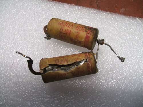
Here's why paper buffer condensers should always be replaced.
The Vibrator.
The heart of the inverter is of course
the vibrator, and in the DuMont it's particularly interesting because of
its size and ruggedness. The vibrator is a standard heavy duty 60 cycle
type housed in a box which plugs into the chassis via two six pin valve
sockets. It appears to be a design based on that developed by Electronic
Laboratories for high power. It has four sets of contacts (Quad Interrupter?).
Because of the size of the reed, two driving coils are used.
They're connected in parallel and have
their own switching contacts. A separate connection is brought out to an
RC network for spark suppression of the driving contacts. This is the 10R
resistor and .5uF condenser. Radio type vibrators being of lower power
can get away with a shorted secondary winding on the driving coil for spark
suppression.
As perfect contact timing is impossible,
more equal current sharing between the power contacts is obtained by having
two primaries on the transformer. As it is, pairs of contacts are paralleled,
but it would be possible to have four primaries. This would only need to
be done for higher powers.
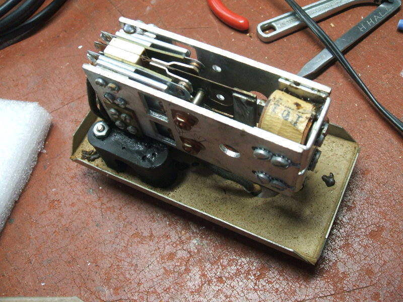
The vibrator stack is mounted on rubber mounts to reduce noise transmission. At some point in the past it appears that two of the screws securing the mounts to the base lost their thread into the rubber, and so have been replaced with nuts and bolts. Also, all the sound deadening material had been removed from inside the cover resulting in noisy operation. Presumably it was something rubber based which had disintegrated and got stuck in the vibrator preventing it operating. The contact condition is excellent, so it appears no one has been plugging in unsuitable loads.
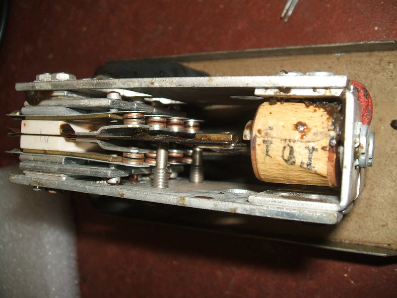
Close up of the contacts. They are individually adjustable by set
screws.
Restoration.
The first thing to do was to remove the
Clipsal 3 pin 240V socket and replace it with the proper NEMA 5-15, 3 pin
120V type. Shortly after this, the 2uF buffer condensers failed. I replaced
them with four 1uF 250V types as I didn't have 2uF on hand. The 3.5uF condensers
should be OK being of the oil filled type. They don't suffer the same kind
of problems as the wax dipped ones. Leakage in the .5uF and remaining
2uF is not a problem at the low voltage they are operating at.
The vibrator itself was in good order
but I cut up some plastic foam to fit in the vibrator cover. It helps reduce
the noise, but ultimately I'll replace it with sponge rubber.
Run into an appropriate light bulb load
there was no sign of untoward operation with very little contact sparking.
Not surprisingly, this confirmed the need to run this inverter under load.
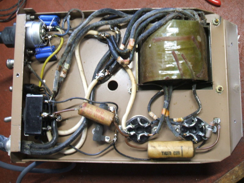
Under the chassis. The new polyester 1uF condensers are visible
connected to the output socket.