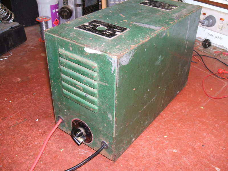
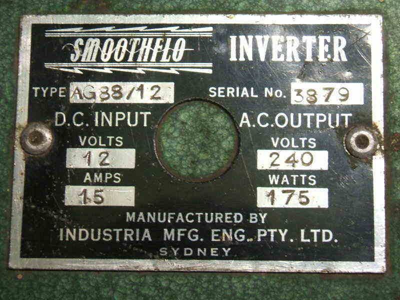
This was found on eBay for $1, and I was
the only bidder. It looked old enough to use a vibrator, and the Smoothflo
name was already familiar to me. This is the third Smoothflo to enter my
collection. My first experience with Smoothflo was with a 30W
inverter, and then more recently with a 15W
inverter.
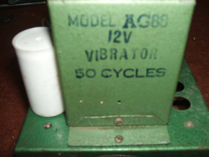
What had me curious more than anything
was what kind of vibrator it might use, being rated at 175W. To date, the
largest vibrators I had seen in Australian made inverters were the Van
Ruyten types used for up to 100W.
I took a scenic drive one Saturday morning
to pick it up from the seller's house at Wilton, to the south west of Sydney.
All I could find out about its history was that "it was used in a Streets
Ice Cream van". What is was actually used to power is unknown, but fluorescent
lighting or maybe a fridge compressor are possibilities.
Once I got it home I couldn't wait to get
it apart. Immediately, I recognised the vibrator as being of the kind used
in my DuMont,
and other large American made inverters. As far as I can tell, it's a type
developed by Electronic Laboratories in the 1930's. The vibrator has four
sets of contacts either side of the reed. These are paralleled into two
connections each side.
Also noticeable was the timing (buffer)
capacitor had been replaced by a modern polypropylene type, with a 1998
date stamp. Evidently, the inverter had been used fairly recently. I then
noticed the battery leads had been replaced, and instead of emerging through
their separate grommets at the front of the chassis, both wires had been
fed through only one of them. There was no fuse to be seen. Both control
knobs were missing.
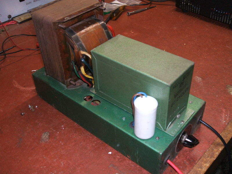
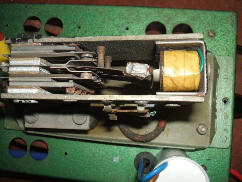
Above chassis view. This photo was taken after the buffer capacitor
had been properly mounted.
The vibrator is interesting because it appears to have been obtained through the military. There's a D^D stamp on it, and it has been resprayed in the same hammertone green as the rest of the inverter. Smoothflo have put their own part number on it. The original military olive green paint is visible inside.
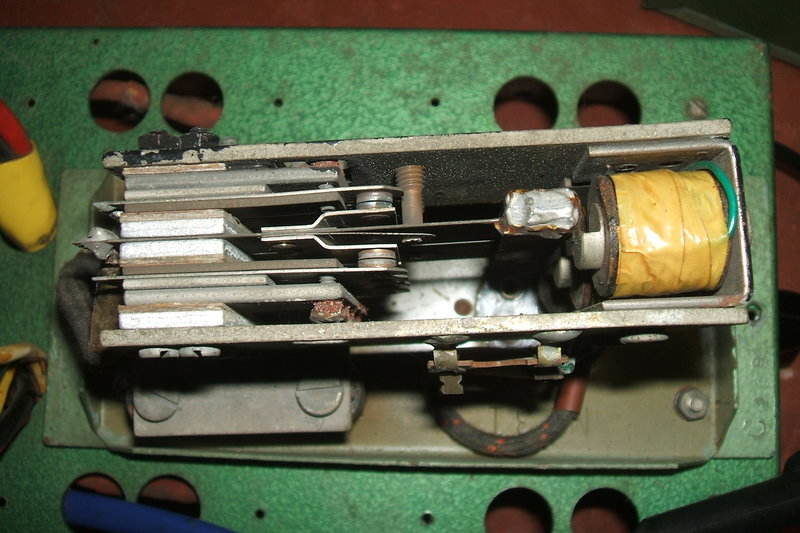
Note the solder added to the reed weight.
To my knowledge, this type of vibrator
was never made in Australia. Because it is U.S. made, it has had solder
added to the reed weight to drop the frequency from its original 60 cycles
to 50 cycles.
This was presumably done locally.
Smoothflo have put their part number on someone else's vibrator.
4uF timing capacitor is at left.
Under the chassis I was a little surprised
to see that for such a high power inverter, the transformer had only one
primary winding. With the vibrator having four sets of contacts per side,
it would have provided better current sharing if there had been two primaries.
The problem is that there's no guarantee all four contacts will close and
open at exactly the same time, all the time. The DuMont inverter has two
primary windings.
As for the transformer itself, this certainly
looks a lot larger than something handling 175W. The core would easily
handle 300VA. Thus, the inverter is quite heavy. However, the large core
size is welcome because of improved efficiency and regulation. As is usual
with this type of inverter, the transformer secondary is tapped to take
account of different loading.
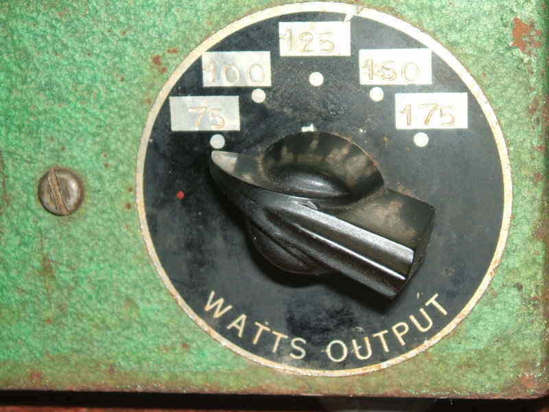
Switch selects one of five secondary tappings on the power transformer.
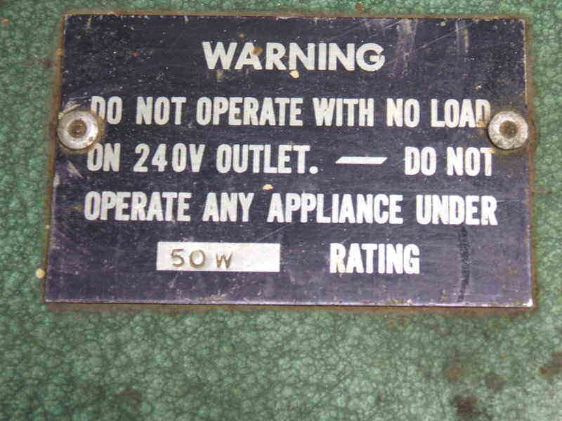
The replacement timing capacitor had me intrigued. Was this the original value? Did someone just put in something that "was near enough"? It had simply been connected to the original wires and left to flop around on the chassis. Despite having a stud mount, no attempt was made to use this or any other kind of clip to secure it. 4uF seemed reasonable enough from previous experience, and it also suggested that the value was actually higher than need be. This was supported by the warnings not to run the inverter with less than 50W load.
And this was another thing, that "backyard quality" inherent in Smoothflo products was evident with how the labels had been attached to the cabinet. They were riveted onto the cabinet without actually measuring anything to see they were centered. The specification plate is the same type used on other inverters where the battery cable passes through the middle. Here, it looks a bit odd with an empty hole in the middle.
Hole in label is used for the battery leads in other models.
Underneath however, the construction quality was pretty good and I couldn't criticise anything there.
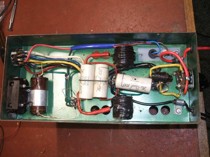
Under the chassis shows neat construction with an easy to trace
circuit.
The UCC "Hi Qual" paper capacitors were
dated 1964 which looked about right given the appearance of the PVC insulated
cable. It's nice to see a vibrator inverter being made this late. The power
switch is a high current type made by Palec. Interestingly, it is a five
position rotary switch. In the left most position, it is off. The next
three positions run the vibrator coil only, and the fifth position also
applies the 12V to the power transformer centre tap.
The idea is that the vibrator should be
operating at its normal amplitude and frequency before current is applied
to its power contacts. This is because when power is first applied to the
driving coil, it takes a small amount of time for it to come up to normal
operating conditions. There's a risk if the inverter is fully loaded there
might be contact arcing before the amplitude and frequency have stabilised.
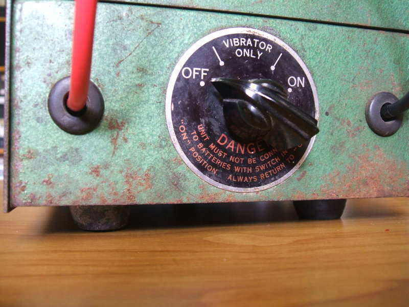
Power switch prevents transformer being powered until the vibrator
has started.
The instructions on the switch label warn against powering up the inverter without going through the start up procedure. This is good design practice, but despite this, I never observed any arcing when starting the inverter fully loaded without bringing the vibrator up to speed first.
Restoration.
The first thing was to confirm the value
of timing capacitor. I had assumed that 4uF was a bit on the large size
because the designers had wanted to maintain the "ideal" waveform under
load. The problem with this is that under no load, the timing capacitance
is much higher than necessary, current draw is higher than normal, and
efficiency is reduced.
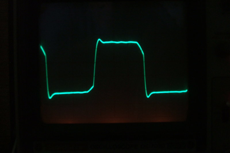
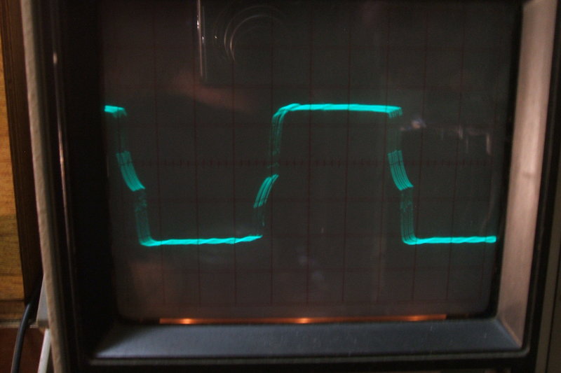
Unloaded waveform with the 4uF buffer capacitor. To the right is
the waveform when 175W of incandescent lamps is connected.
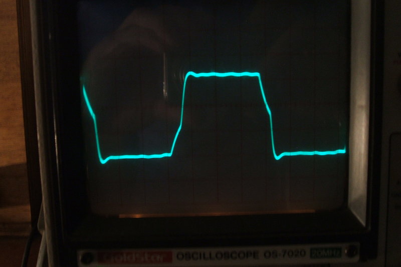
It is more efficient to select the timing capacitor for minimal primary current with no load. I experimented with this and found the ideal capacitance to be 1.5uF. There was however some overshoot, as if the circuit needed damping, and indeed 250 ohms in series with the 1.5uF gave a very nice waveform.
Unloaded waveform with 1.5uF in series with 250 ohms as the buffer.
To the right is with the 175W of incandescent lamps connected. Ignore the
jitter in the trace - this was a result of imperfect triggering.
This actually worked very well, and inverter efficiency at low loading was improved. However, one advantage of the 4uF was that it meant the inverter could cope better with inductive loads. In other words, loads like non power factor corrected fluorescent lamps could be used without causing any contact arcing. The reality is, with an inverter of this power rating, loads like motors and fluorescent lamps are likely to be used. After all, apart from television sets, what else is there that is totally resistive up around 175W, apart from incandescent lamps?
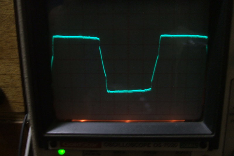
I tried a low power factor 2x 20W (i.e. 40W) fluorescent lamp with both buffer capacitors, and at no time with the 4uF was there any contact arcing. With the 1.5uF there wasn't any either, except when the lamp was starting. The fluorescent lamp actually drew 46W (6W of ballast losses), and had a power factor of .52.
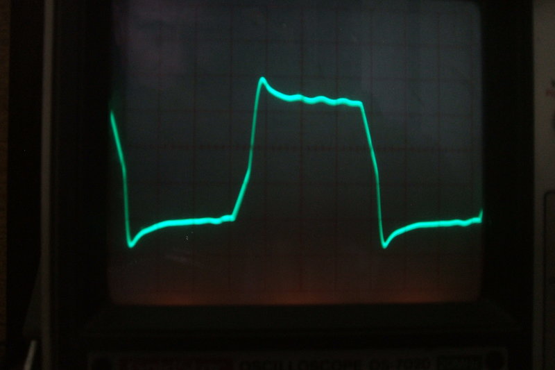
40W fluorescent lamp with low power factor operating with 4uF timing
capacitor. Overshoot is tolerable.
| Timing Capacitor | 4uF | 1.5uF + 200R |
| No load current | 4.5A | 2.2A |
| 175W resistive | 18.5A | 17.5A |
| 46W inductive ( .52 PF) | 5.2A | 5.2A |
The table above compares current consumption
at 12V, versus 4uF and 1.5uF timing capacitors. As can be seen, efficiency
is poorest with no load (or low resistive loading) with the larger timing
capacitor.
By the time the inverter is fully loaded,
the difference is not significant.
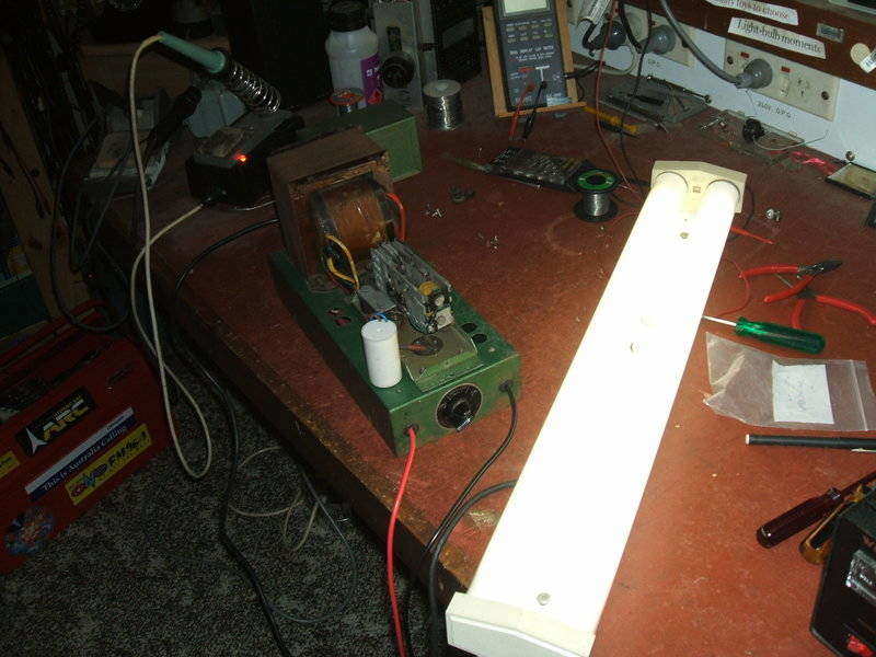
Fluorescent lamp under test to observe the effect of low power factor
loads.
In view of the likelihood of a non power factor corrected fluorescent lamp being used, or other inductive loads, it was decided to retain the 4uF timing capacitor. As it is, using this inverter for smaller loads is not very efficient anyway due to the high consumption of the vibrator driver coils. With around 25W in inverter losses even with a 1.5uF timing capacitor, it makes no sense to be powering something like a 30W valve radio. In this situation it is far more efficient to use a smaller inverter.
The Circuit.
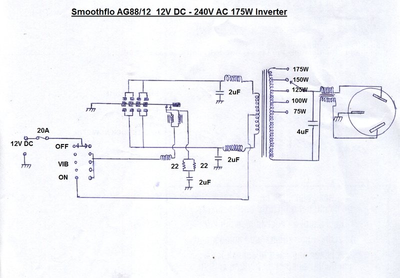
There is nothing out of the ordinary in
this design, except perhaps that the timing capacitor is connected after
the transformer tapping switch. This means the reflected capacitance depends
on the switch setting. It's an unusual arrangement, but given that the
capacitance is higher than necessary, does not present any practical problems.
If anything, the current consumption is reduced on the lower tappings.
It is true that if the switch is adjusted
with the inverter running that in between positions there would be no buffer
capacitance.
The circuit is standard for this kind of inverter otherwise. The vibrator has two driving coils in view of the large reed and extra contacts. A series drive arrangement is used so that the reed vibrates independently of any loading variation, and the condition of the power contacts. There are also two driving coil contacts connected in parallel. An arc suppressor consisting of a 2uF capacitor and two 22R resistors connects across the driving coil contacts. It is a curious thing why a single 10R 1W resistor was not used instead of the two 1/2W 22R types.
2uF capacitors are connected directly across the vibrator's power contacts. This means the contacts short circuit the capacitors each time they close. However, being paper types, and given the discharge current is not particularly high at 12V, they can tolerate this. An excess amount of capacitance would actually cause arcing rather than suppressing it. In any case, the inverter has been well used and the contacts are in excellent condition, so the design appears to be acceptable. Given the low voltage to which they are exposed, and that any leakage is unimportant, the paper capacitors were left in situ.
Air cored chokes are included in series with the primary winding connections and the vibrator driving coil. There is what appears to be a common mode choke in series with the 240V socket. Output is balanced, with the earth terminal of the socket connected to the chassis. There are no other attempts at RFI suppression. While I did not try a radio, I did power a television set and there was no RFI evident. Surprisingly, there are no bypass capacitors in the 12V supply circuit. Being a vibrator inverter, input polarity is unimportant for it to operate. Only when used in a metal vehicle for example, and there is a risk of short circuits, does the cabinet need to be at the same potential as that of the vehicle body.
Compared to their other two inverters in
my collection, Smoothflo seem to have got this one right. It has quite
good regulation with 240V being produced, consistent with the output switch
tapping, and with 12V at the start of the battery leads. I could not see
any vibrator contact arcing with any of the loads I used.
The power supply used for testing was
a 30A Welz RS3050. It was necessary to bypass its terminals with 10,000uF
because spikes from the inverter when starting the fluorescent lamp would
trip the power supply's crowbar circuit.
I think the warning labels are a bit conservative. There was no arcing running on no load, and nor was any arcing visible if the inverter was started with the transformer in circuit. The only risk in using less than 50W of loading might simply be a higher output voltage, and just poor efficiency.
Vibrator in action with reed frozen due to camera shutter speed.