I had seen this cute little inverter advertised
in Radio & Hobbies and often wondered how they fitted everything into
such a small box. When one turned up on eBay, it was just natural I had
to have it.
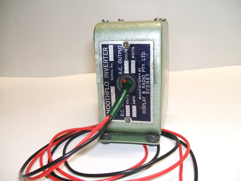
It was made by Smoothflo in Sydney, and
converts 6VDC to 240VAC, 100c/s, 15W. In
this article I describe a 30W inverter also made by Smoothflo.
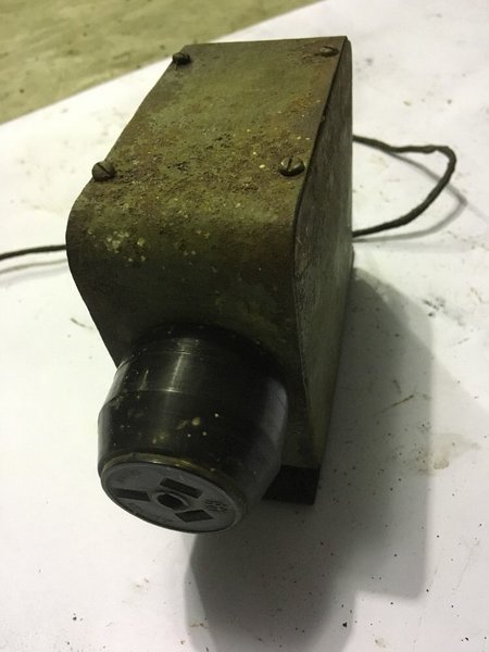
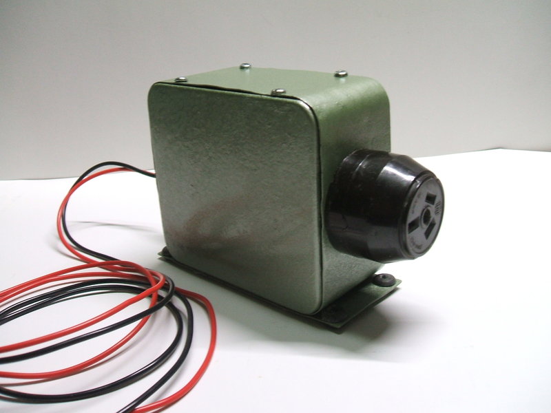
A respray in green hammertone took care of the cosmetics. To the
right is the inverter in original condition.
Interestingly, with this inverter, "Smoothflo"
is made by Display & Radio Pty. Ltd, whereas the my 30W inverter is
made by Industria Mfg. Eng. Pty. Ltd. The latter name also belongs to another,
later, 1960's vintage inverter I have.
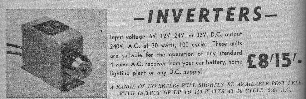
This advertisement from 1951 claims an output of 30W. This is impossible
given the size of transformer that can fit in the box.
Cosmetically, the inverter as I received
it, was very poor. Immediately, I resprayed the case in green hammertone.
The rubber feet were missing, so these were replaced with similar size
grommets.
The inverter had obviously been got at,
because the sides of the box had been prised open.
This type of construction with a tight
fitting lid, fitting on the inside of the box, is also used with the 30W
inverter, and is equally difficult to remove. The vibrator had also been
opened, as the earth tag had been broken, and there were marks around the
phenolic base where the spring clip had been removed.
The shielded supply cable was a tatty
mess so it was replaced with red and black wires. As with the 30W inverter,
there was no sign of a fuse being included.
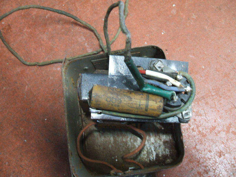
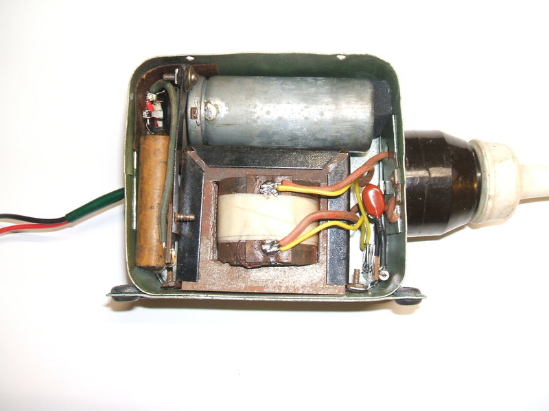
The circuit was much as expected, with an Oak/MSP V5105 non synchronous vibrator driving a transformer and the usual timing condenser. The vibrator socket is mounted on a rectangular piece of steel that has been spot welded to the transformer mounting strap. The socket is mounted on rubber grommets, obviously meant to reduce the acoustic noise, but given how tight everything is, causing the vibrator can to be pushed against the transformer, it was pointless including them. A partially silverfish eaten piece of corrugated cardboard prevented the transformer secondary terminals shorting against the lid, and a piece of elephanthide paper was squeezed in at the back of the vibrator socket to prevent its pins touching the case.
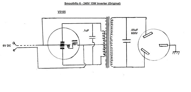
This was the circuit of the inverter as manufactured. It contained
a number of design faults.
In its original form, a shielded cable
conveys the 6VDC into the inverter, where it is applied to the vibrator
via the transformer primary in the usual way. There was a .05uF 600V Ducon
paper condenser connected to the secondary, obviously the timing capacitor,
and an HPM 3 pin socket provides the 240VAC to the outside world. The inverter
is rated at 15W, and by the look of the transformer core size that would
appear to be correct. As the vibrator is an ordinary radio type, the frequency
is 100 c/s. Across the primary winding was a .1uF 600V Ducon paper condenser.
It seemed a strange location for this component, as a value that low on
the primary will have no effect as far as timing capacitance goes. I could
only assume it was intended for some kind of RFI suppression. Despite the
braided cable coming into the inverter, there is no bypassing on the DC
input, and neither was the braid connected directly to the case. Furthermore,
the three pin socket has its earth terminal connected to the case, but
this goes nowhere else.
Remembering the 30W inverter, I was not
overly surprised at all this, but this was nothing compared to what I found
later.
As to what this inverter was meant to
power, one can assume the most likely thing is a shaver that does not care
about frequency (i.e. a motor driven AC/DC type). When this inverter was
made, the only kind of radio that could conceivably be run off the 15W
would be one of the live chassis Astor battery / mains portables. The total
current for such a receiver would be about 60mA (50mA "A" and 10mA "B"),
which equates to 15W.
Any conventional mantel type radio with
indirectly heated valves would require about twice the power at least.
While it's perfectly practical to run a 240V 15W incandescent bulb, purchasing
an inverter specifically for that is an unnecessary cost, when one can
simply run a bulb (and a higher wattage one at that) straight off the battery.
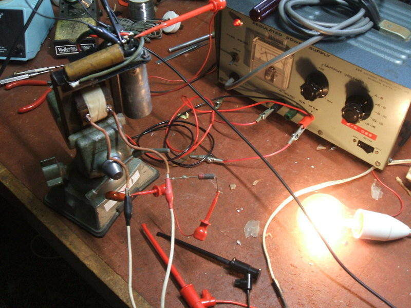
Getting it going.
The first step was to check the vibrator.
Connected up to my vibrator
test panel, it was obvious the contacts had insulating film on them.
That's to be expected with years of disuse, so I electrically cleaned the
contacts with a 100W lamp in series, fed from isolated 240VAC. There
was no evidence anything had been done to the vibrator, and the contacts
were in excellent condition, so it is a mystery as to why it had been opened
previously. The paper label had largely been eaten by silverfish, but I
could make out someone had written "15 watts" on it in red Biro.
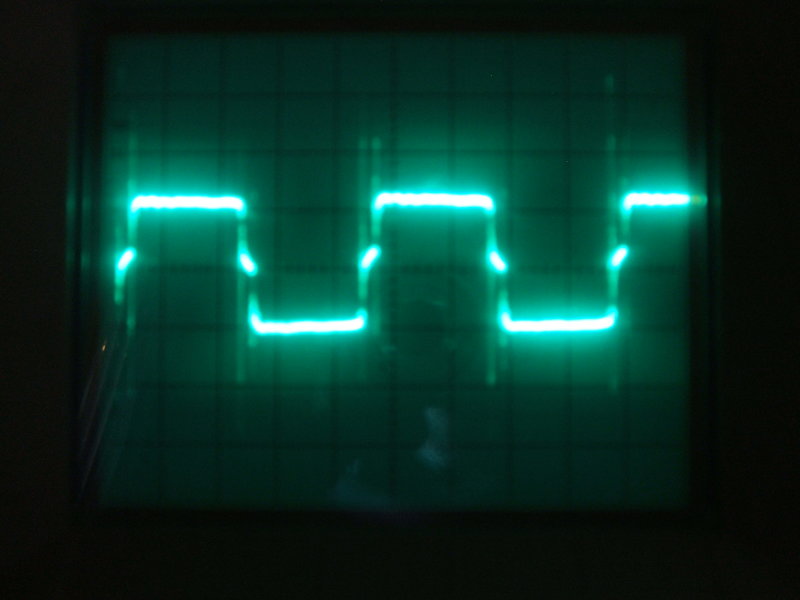
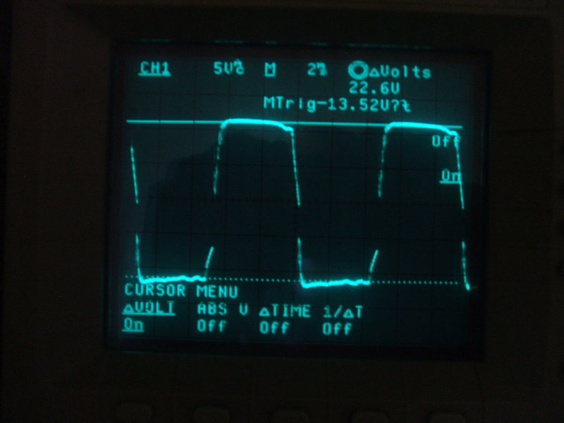
The contact duty cycle was checked, and
found to also be excellent.
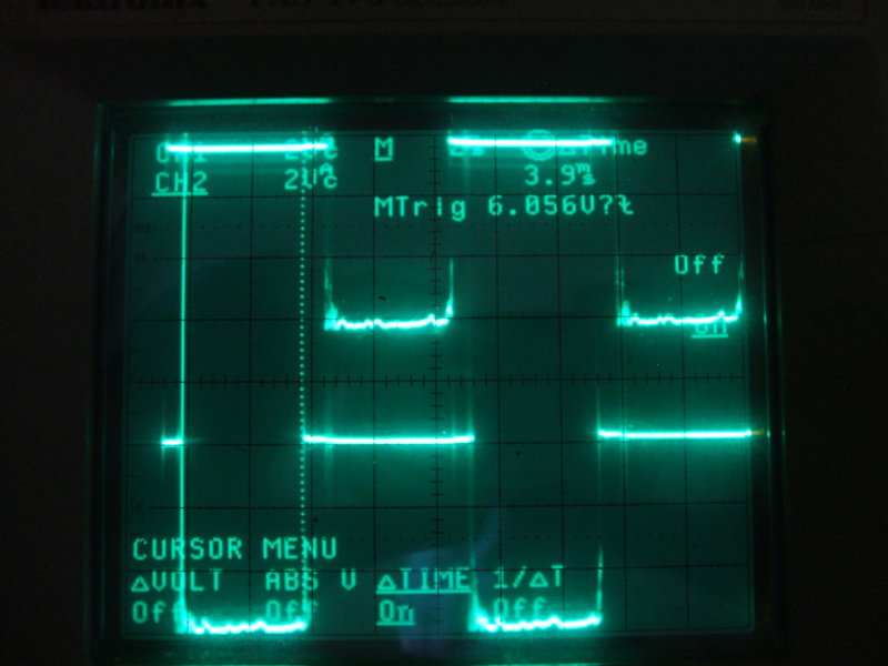
Timing waveforms showing the on and off times (i.e. the duty cycle,
or "time efficiency" as Mallory calls it) of the vibrator.
Design Fault.
Now, the inverter was ready to be tested.
Just out of curiosity I left the original buffer in and powered it up with
a 15W bulb as a load. It lit up, but it was obvious the timing capacitor
was leaky. I substituted a polyester type which seemed to restore normality.
It was at this point I discovered we had a major problem on our hands,
which eventually revealed itself as a serious design fault. In fact, it
was so bad I wonder what circumstances this inverter had been used in,
and if the loads it had been used with had been damaged.
The bulb looked like it was brighter than
normal, but the most noticeable thing was the excessive current consumption.
With 6VDC at the vibrator socket, the current draw was 4.5A! Now, a simple
calculation will reveal that 15W at 6V is closer to 2.5A. As to the output
voltage, that was 345V as measured on the AC range of a Fluke 8000A. I
realise that this is an average measurement, but for a vibrator waveform,
the rms is not hugely different; certainly not to anything like that degree
(the average and rms differ by about 10V). The waveform was equally atrocious
with excess ringing, and a strange overshoot when running unloaded.
The unloaded voltage was up around 420V
which was obviously unacceptable, not just for the timing condenser, but
also for the transformer insulation.
Remembering the 30W inverter and the incorrect
timing condenser, I considered this inverter might be similarly affected,
but tests with other values showed it to be correct.
What could possibly cause the excess output
voltage? A shorted turn on the primary could conceivably do that. Thoughts
turned to rewinding the transformer, but as the primary is on the inside
of the core, thousands of turns of the secondary would have to be taken
off first. I also thought about replacing the transformer with a modern
type, but the problem there was finding something that would fit in the
box.
I decided to investigate the transformer more closely. Testing it on an inductance and Q meter showed that shorted turns were actually not likely to be the problem. Feeding 240VAC into the transformer secondary (240V winding) showed a magnetising current of only 10.8mA. That is actually very good, and there was no doubt this was not the problem. Measuring the low voltage winding was showing about 2.7V either side of the centre tap. This seemed extraordinarily low, given that it should be around 4.5V.
Wrong Turns Ratio.
It was now clear what the problem was
- the transformer simply had an excessive turns ratio. How this came to
be is perplexing, but I did further tests. I found that to get 240VAC at
15W, the DC input at the vibrator socket needed to be 4.5V. Current now
was a little under 4A. The current specification on the label is 3.7A which
is absurd, and given the 30W inverter was similarly labelled with a ridiculous
current, I simply ignored it.
At the power supply end of the supply
leads, the voltage was close to 5V. My only conclusion was that someone
had designed the transformer to suit a 6V battery that was a little undercharged
and a supply cable dropping about half a volt.
An important thing to remember is that
a 6 to 240V inverter multiplies any change in voltage on the 6V side by
40 times. So, imagine if this inverter was used in a car with the battery
charging at 7V.
Obviously, this is extremely poor design.
This being the second Smoothflo inverter I've restored, and both with design
/ manufacturing faults make me think the designers were incompetent with
vibrator power supplies.
In the real world, allowing for regulation,
battery voltage, and drop along the supply leads, a suitable compromise
is to aim for 230V with a 15W load, when there is 6V at the vibrator socket.
With about half a volt drop along the supply cables, that allows for a
properly charged 6V battery. The concept of expecting the battery to be
undercharged is ridiculous, if not only for the damage caused to the battery.
With a higher voltage as when the battery
is under charge, the output should not go much higher than 250 -
260V.
Modifying the Transformer.
The next thing was to remove turns off
the secondary, but the question is how many? I wound seven turns of copper
wire through the core of the transformer, and by measuring the voltage
(612mV) was able to calculate a turns per volt ratio of about 11.6
turns per volt. Playing safe, I removed 580 turns, and this provided 284Vrms
into 15W with 6V at the vibrator socket. So far things looked promising,
but the voltage was still too high. So, off with another 580 turns, and
perfection. Now, the output was 227Vrms into 15W with 6V at the vibrator
socket. The input current was now about 2.5A, where it should be.
This is just unbelievable that I had to
remove 1160 turns - what an appalling stuff up!
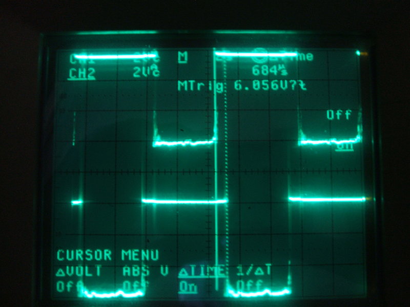
With the output voltage now sorted, there
was still the waveform to deal with. Under load it looked OK, but off load
it had this strange overshoot at the start of the peak,
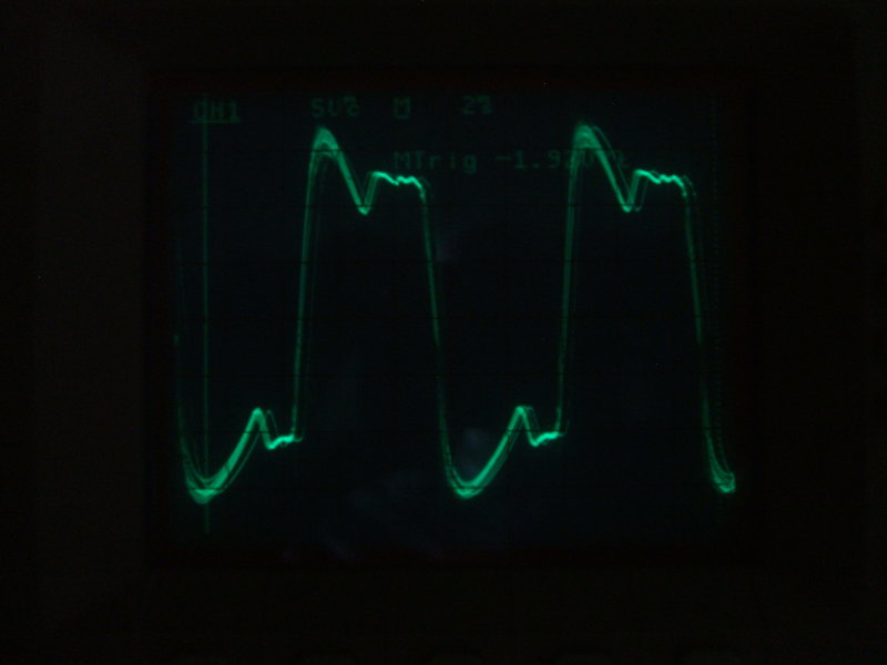
Unloaded waveform had a strange overshoot with the original buffer
circuit.
This would appear to be an oscillation
caused by a spurious inductance resonating with the timing condenser, possibly
the transformer's leakage inductance.
Many vibrator power supplies incorporate
a resistor in series with the timing condenser to damp out this oscillation,
so I followed suit. With no load, I found 4.7K to be a suitable resistance,
this being the lowest resistance that flattens the overshoot.
Contrary to what some articles say, these
resistors are not to limit current or act as fuses in case the timing
condenser shorts. The resistor(s) may well act that way, but if they
do, the inverter continues to run with no timing capacitance, which unbeknown
to the user, is quickly ruining the vibrator. If a timing condenser shorts
out, it should cause the supply fuse to blow so the inverter stops altogether,
not just burn out a resistor and keep working until the vibrator is ruined.
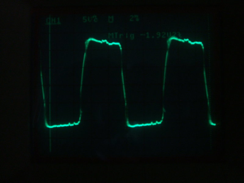
Damping resistor successfully removed the no load overshoot. Output
is unloaded.
Incidentally, the correct place to measure these waveforms is at the vibrator contacts, because this is what the vibrator sees. With the waveforms here, I connected the CRO across the full primary of the transformer, but this requires the DC power supply to be isolated from earth.
The next strange waveform to deal with was a high frequency oscillation/overshoot present when operating under load.
Spikes caused by the .1uF primary condenser. Inverter is operating
under load into a 15W light bulb.
It could be observed with the CRO brightness up high. As can be seen, the spikes occur when the vibrator is switching. For a while I thought it could be the condition of the contacts, given when they occur. However, on the vibrator test panel, the contacts looked good. Nevertheless, I temporarily substituted a brand new, out of the box Mallory vibrator, and the spikes were still there. That eliminated the vibrator. So what next? Well, it could be more spurious oscillation, but caused by what? There was that .1uF across the primary which I hadn't taken a lot of notice of, but it could be like the timing capacitor across the secondary, and be resonating with something. Taking it out of circuit fixed the problem. The Mallory notes mention that a primary condenser can cause this effect because of the direct connection to the vibrator contacts and the charge current. As far as I can ascertain it is not harmful, but in this case the .1uF served no purpose.
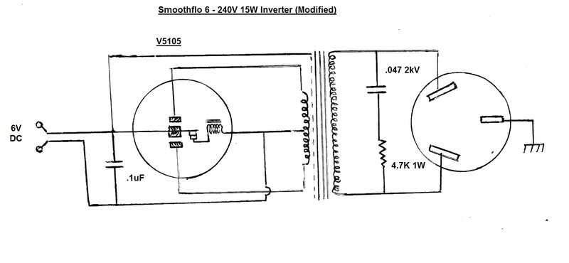
Circuit of the modified inverter. Apart from removing 1160 secondary
turns, the buffer circuit required a 4.7K damping resistor, and the .1uF
had to be removed from the primary.
Final primary waveform. Secondary is unloaded.
No complaints now, and the waveform wasn't bad for a vibrator inverter. The .1uF was relocated across the DC input where it actually did some good by removing a lot of RFI. In fact, I was quite surprised how well a solid state AM radio worked off this inverter, given the lack of attention to RFI suppression.
Testing the secondary damping resistor. At this time the resistor
was 2.2K.
The inverter was now working happily at last, and I let it run a 15W bulb all afternoon. No vibrator sparking, no warm transformer, and the correct 2.5A draw at 6V. Next thing to do was shoehorn it all back into the tiny case.
Crammed into the box, the whole thing is a very tight fit.
The timing condenser had originally been soldered directly to the transformer terminal strip, but now with the 4.7K resistor in circuit, I added a four lug tagstrip to mount it and the condenser. This mounted conveniently under the front transformer screw. I also added a piece of foam rubber between the case and the top of the vibrator. Without this, the vibrator could easily fall out of the socket (it had done so already by the time I received the inverter).
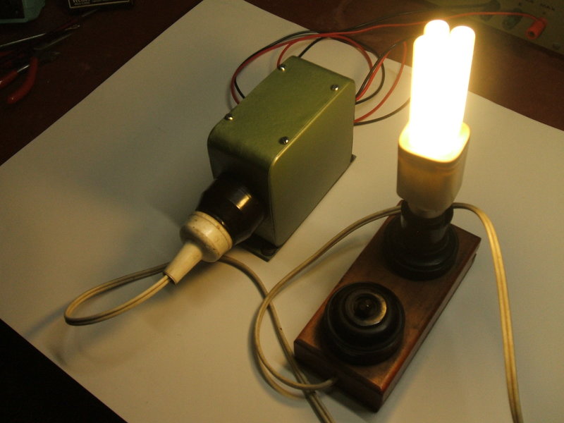
Not often does one see a CFL operating off 6V, but with a vintage
inverter like this, it is quite practical.
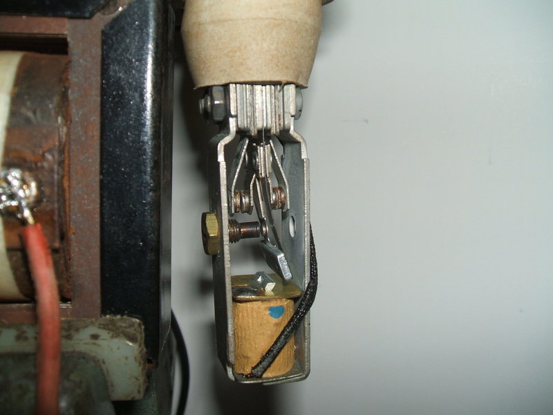
Caught in the act! A fluke of photography during the restoration
shows the vibrator in action with the reed swung over to one side. The
driving contact appears to have just opened.
Smoothflo in the Model T Ford.
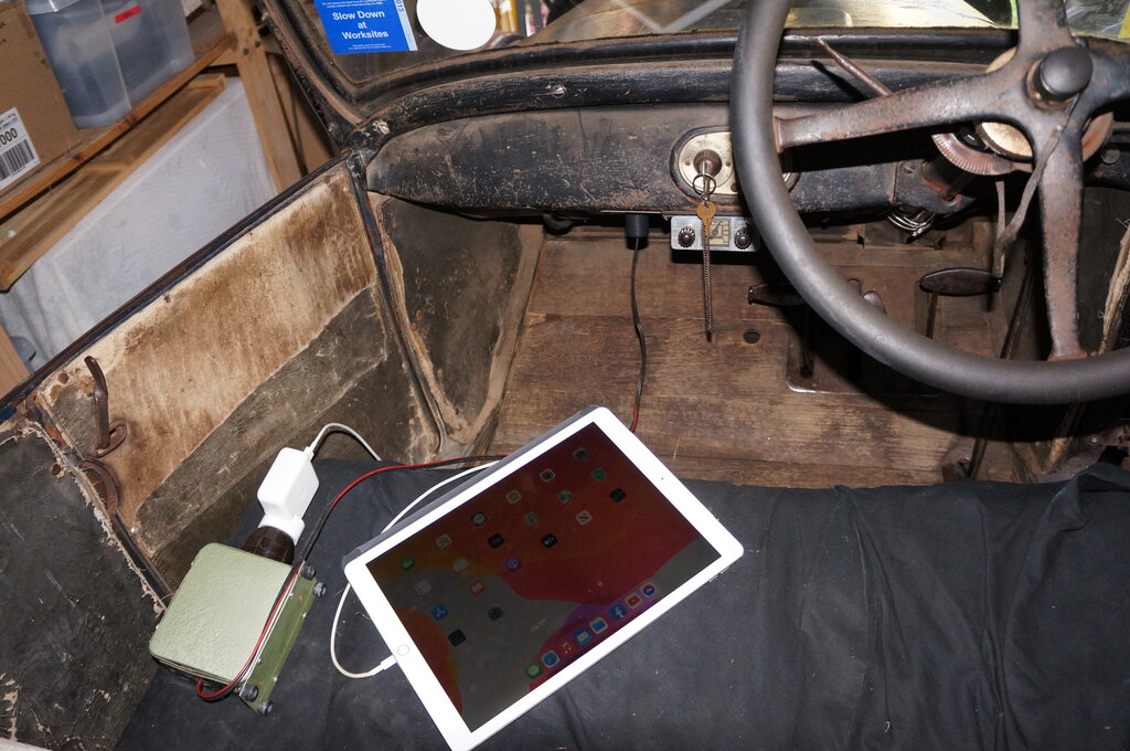
Modern and old technology working together.
Since acquiring an iPad and wanting to use it in the Model T, the 15W Smoothflo was ideal for charging it. Current draw is just under 2A. I had recently fitted a cigarette lighter socket for powering 6V appliances, and the Smoothflo works perfectly from it. A minor alteration was done to the inverter, in that a fused cigarette lighter plug was fitted, which is much neater than the inline fuse holder. The supply lead was replaced with figure eight flex, and a proper earth connection was made between the negative and the chassis of the inverter.
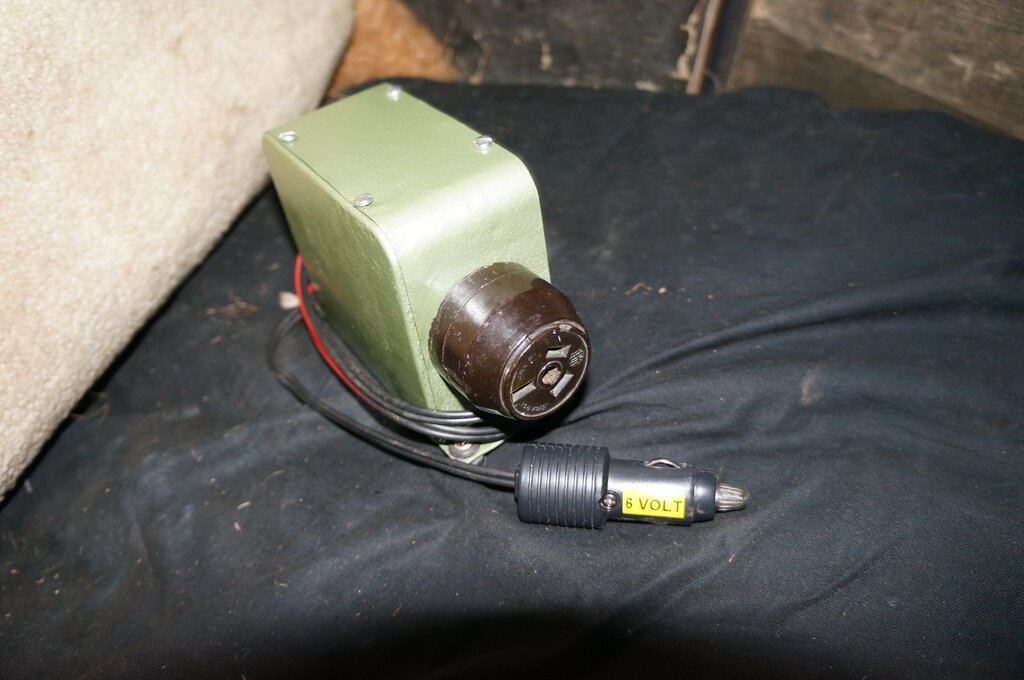
Inverter fitted with fused cigarette lighter plug.
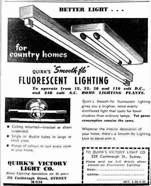
Another Smoothflo product. Undoubtedly the 12, 32, and 50V, and
possibly the 110V, models would use a vibrator inverter.