This set came to me for restoration from
another early Falcon enthusiast. From the manufacturing date on the radio
being 1960, I soon worked out it belonged to an XK, which was the first
Australian model of Ford Falcon.
This is the first hybrid car radio to
be described on this site. It was manufactured by AWA, and given the model
number 966-A.
Hybrid sets were popular in Australia
from around 1959 to 1962. They were the 'interim' technology between all-valve
and all-transistor sets.
When transistors first became available
for consumer use in the late 1950's, they were not entirely suited for
an all transistor car radio. The summer temperatures inside a car could
be problematic for the heat sensitive germanium transistors used in the
RF and IF circuitry.
As a compromise, valves were retained
for the front end, and more rugged transistors used for the audio section.
Since the front end valves will actually work quite well with only 12V
B+, there is now no need for the vibrator power supply. It is impossible
to get more than milliwatts of audio power from a valve audio amplifier
operating at 12V, hence the need for 200 odd volts and the vibrator power
supply previously used.
For a more detailed description of low
voltage valve operation, this
article describes a full superhet using ordinary valves at 12V.
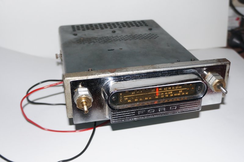
The AWA 966-A.
This is one of AWA's wedge shaped designs
which had its origins around the mid 1950's with the 930-A
/ 931-A. These were six valve vibrator sets sold under the "Cruiser"
or "Cruisermatic" names. The last version was the 945-A / 946-A produced
in 1965.
However, a few hybrid models used the
same case and chassis. The rear section of the set where the vibrator,
transformer, and rectifier once resided were now replaced by a heatsink
and transistor output stage.
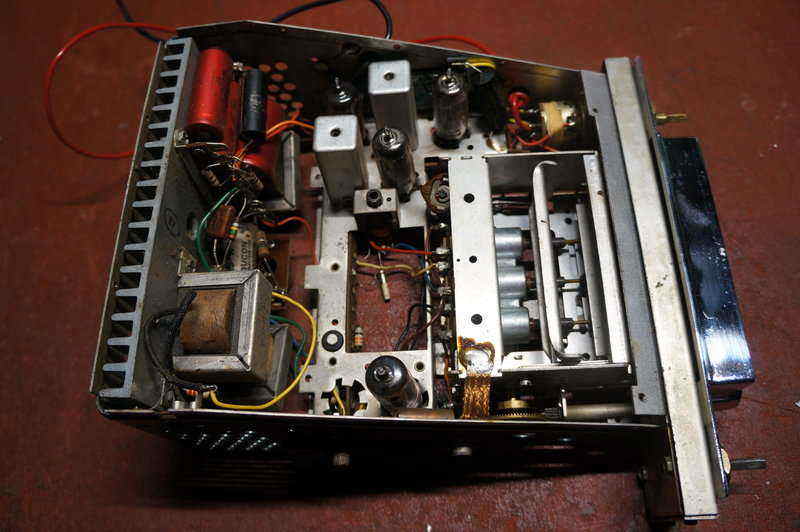
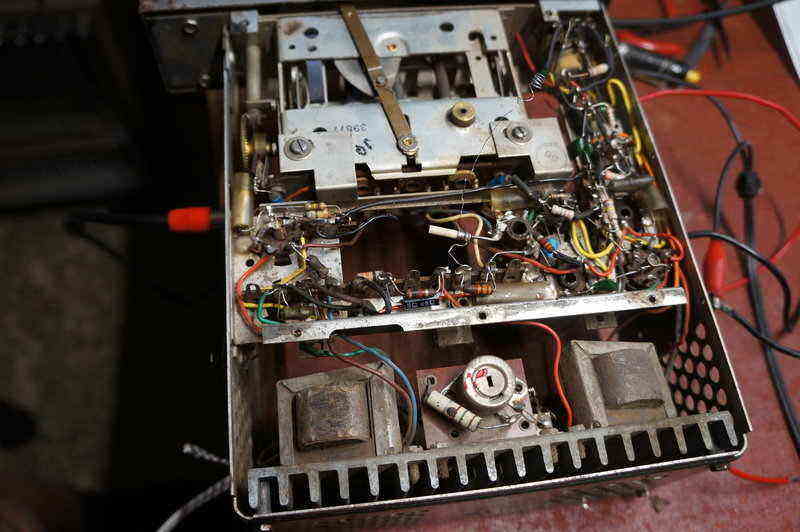
Rear section of set originally contained a vibrator power supply.
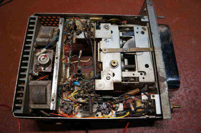
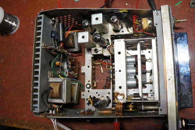
The front end of the set is laid out exactly the same as the all-valve predecessor, with the IF transformers, valve sockets, and tuning unit, in the same position. Essentially, all that has changed is the 12V valve types, and the circuit being fed with only 12V.
The Circuit.
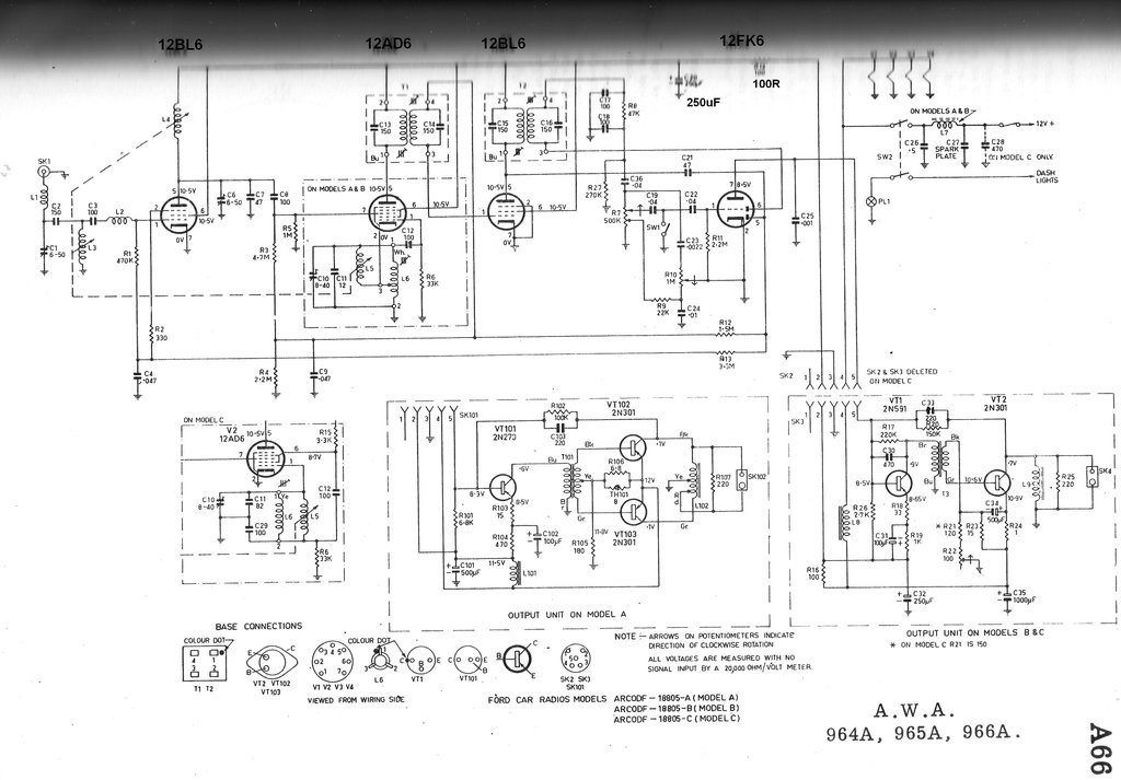
The set described is the Model C version.
Incoming signal is tuned by the stray capacitance
of the aerial (around 100pF), C1 and C2, with L3 being the variable element
of the circuit.
The set is of course permeability tuned,
which was by now standard for car radios. L1 is the ignition filter. It
presents a high impedance around 40Mc/s where ignition interference is
at its greatest intensity.
The RF amplifier is a 12BL6. This is essentially
a carefully manufactured 12BA6. Its plate load is tuned by L4, C6 and C7,
and the amplified signal then fed into the signal grid of the 12AD6. This
is a converter equivalent to 12BE6. The local oscillator is tuned by L5,
L6, C10, C11, and C29.
IF from the 12AD6 plate proceeds to the
IF amplifier via T1, a double tuned IF transformer. The IF amplifier is
a 12BL6. Plate load is the second IF transformer, T2. The secondary of
this feeds one diode of the 12FK6, equivalent to 12AV6, for detection.
The other diode generates AVC, and is shunt fed from the 12BL6 plate via
C21. AVC feeds the RF amplifier control grid via the filter consisting
of R13 and C4. The converter and IF amplifier have a separate AVC filter
consisting of R12 and C9. It will be noted that the AVC for these two stages
is reduced by the presence of R4. This in conjunction with R12 acts as
a voltage divider. With such a low plate voltage, it would be easy to cut
off these stages entirely, much sooner than when operated at a more 'normal'
B+.
The detected IF is filtered in the normal
way by C17, C18, and R8, leaving just the audio component. This feeds a
loudness compensated volume control, and then the grid of the 12FK6 triode.
R10 is a tone control. At the low setting, the high frequency component
of the audio signal is shunted to earth by C23. For the high setting, the
loudness circuit is shunted to earth via R9, and C23 is isolated by 1M
of resistance. S1 is not included in this version of the 966-A (Model C).
It is for the push button tuned models, and shorts out the audio when stations
are tuned by the push buttons. The purpose of this is to silence the perhaps
undesirable sound, as the receiver is suddenly tuned across several stations
when a button is pushed.
Transistor Amplifier.
This consists of a 2N591 driver and 2N301
output transistor. The 12FK6 plate is directly coupled to the 2N591 base,
which provides some of the required bias, along with R17. Thus, the conduction
of the 12FK6 determines the bias for the 2N591.
Note that as the transistors are PNP types,
the collectors are on the earthy side of the circuit (this being because
of the negative earth requirement). The 2N591 bias is stabilised by the
emitter resistor R19, with some AC feedback via R18. Collector load is
driver transformer T3. Since R17 is connected to the collector, it creates
some local feedback to help reduce distortion.
The output stage is biassed to 400mA,
thus operating in class A. Base bias comes from the voltage divider consisting
of R21, R22, and R23. It is stabilised by emitter resistor/choke, R24.
This component is shown schematically as a resistor, but is in actual fact
a choke, carefully made to be of 1 ohm resistance. Using a choke here provides
AC stability. Previous experience shows that a wire wound resistor can
be used as a replacement, should this choke be burned up due to a shorted
output transistor. Collector load is the choke L9, which shunt feeds the
15R speaker. The choke has a high impedance at audio frequency, and is
included so that minimal DC flows through the speaker voice coil. Additionally,
if it were not for the choke, there would be loss of collector voltage
across the voice coil resistance.
The Model A version uses a more powerful
push-pull class B amplifier.
Restoration Begins.
Just out of curiosity I powered the set
up as I received it. It was, as the owner said, dead. That is, until I
connected the aerial input to my long wire outdoor aerial. Some stations
could be heard weakly, but the dial calibration was also way off. I was
hoping this would all clear up after the resistor and capacitor replacement.
Three lots of components needed replacing.
Electrolytic capacitors, particularly low value types, of the age of those
in this set, were now doubtful. There were numerous paper capacitors, of
the AEE metalised paper type, which first appeared around 1956. Being paper
means they're now leaky to a lesser or greater degree. In the case of transistor
circuitry, they could in theory be left in situ since the impedances are
low, but in the case of valve circuits, performance is likely to be affected.
In any case, what leakage there is will only get worse as time goes on.
As this was an expensive repair, where reliability was to be made as good
as sensibly possible, the obvious thing is to replace them all. Finally,
there are the carbon resistors. Again, these deteriorate over time, especially
the high values. Thus, anything over 100k was replaced. Last but not least,
was the mica capacitor C33 in the audio feedback circuit. These are now
unreliable enough to warrant replacement in audio circuits. They are often
the source of intermittent faults, particularly scratching sounds heard
from time to time.
And so, after about five hours work, all
the relevant parts had been replaced. This is the time consuming tedious
part of the job, which I doubt few non-technical people appreciate. Unfortunately,
AWA was one of many manufacturers who insist on wrapping component leads
right around the tagstrips and valve socket pins. It makes for difficult
removal, as the lead has to be unwound while the solder is kept in a melted
state. In all my years of electronic construction I've never found it necessary
to do this. The solder alone is more than adequate to make a secure mechanical
connection. The reason for the leads being twisted around tags is actually
to do with the manufacturing. The components were installed first on the
assembly line, and then the soldering was done further down by another
operator. Thus, it was necessary to make sure the parts were secure mechanically
first.
The Challenges Begin.
During the resistor replacement, by chance
I measured R5, the 1M 12AD6 signal grid resistor, before replacing it.
I was somewhat surprised to see it reading 105k. It is extremely rare for
a resistor to reduce value like that, so I started disconnecting other
components to find where the low resistance was. In the end, it was found
to be internal to the 12AD6. The resistance was between pin 5 (plate) and
7 (signal grid). This is strange because there is a suppressor grid between
these two electrodes, which did not show any resistance reading. I simply
burned it out using a picture tube reactivator. After that, there was an
open circuit between plate and grid, as there should be.
With such a high leakage between pin 5
and 7, the signal grid would have been biassed positive which would explain
the extreme lack of sensitivity. What caused the leakage will never be
known. Quite possibly it was a fragment of material loose inside.
Anyway, the set could receive a few signals
now on the car aerial, but the dial calibration still was way out. There's
a station around 1629kHz in my area which was appearing almost half way
down the dial. This was a lot more than just a bit of alignment drift.
Trimmer Capacitors.
The sensitivity seemed a lot better when
the aerial was connected directly to the converter, bypassing the RF amplifier.
This is the opposite of what should be happening. So why was the RF amplifier
acting as an attenuator instead of an amplifier?
While pondering this, I thought at least
I could get on with one obvious thing that needed repair; the aerial trimmer,
C1. Someone had been a bit careless in the past, and the adjustment shaft
had a force applied to it which was never intended. The bakelite trimmer
casing was broken in several sections. It looked like it could be super
glued back together easily enough, so it was extracted and dismantled.
However, I still thought the glued join might not survive the rough treatment
it was likely to get in the future. Then I had an idea...I noticed that
the RF amplifier trimmer, C6, was of the same construction. I could swap
the trimmers over, since the more delicate one would be quite OK inside
the set. To do this entailed swapping over the control shaft of the aerial
trimmer with the screw adjustment of the RF trimmer. It all went to plan
and the trimmers were duly replaced. Surprisingly, sensitivity was considerably
improved, and the RF amplifier was doing its job.
It would appear there was some foreign
matter lodged in between the plates of C6 which fell out when I dismantled
it. This would explain why the trimmer wouldn't peak.
Local Oscillator.
Aside from the local oscillator, the only
thing that could cause the stations to appear at the wrong dial locations
would be if the IF channel was way off frequency. That was worth a check
first. It was close to the expected 455Kc/s, although some improvement
in gain was had by tweaking all the IF transformers. This is easy to do
with a weak 455Kc/s signal fed into pin 7 of the 12AD6, and each IF transformer
adjusted for maximum audio output. Note that IF transformer cores
should be adjusted for peaking towards the outer ends of the coil formers,
to get the intended coupling characteristic.
Obviously, the local oscillator was still
way off. In fact, the lowest frequency the receiver could be tuned to was
600kc/s. It should be 530kc/s.
I checked all the capacitors associated
with the local oscillator and found no fault. There was only one thing
left to try and that was adjusting L6, which AWA calls the "padder" adjustment.
Normally a padder is a series capacitor in the tuned circuit, but because
this set uses permeability tuning, a coil is used instead. L6 is in parallel
with the local oscillator coil (L5), which is tuned by the user. Adjusting
L6 effectively controls the inductance range of L5.
And so, careful adjustment did bring forth
the ability to tune down to 530Kc/s. As expected, now that the tracking
was better, the sensitivity was improved. As well as L6, C10 has to be
adjusted to set the upper limit of reception. In this set it's a trimmer
which I believe is of Philips origin. This trimmer capacitor consists of
a ceramic tube with one conductor running up the centre. The other connection
is to a fine wire wound around the tube. As more wire is wound on, capacitance
can be increased, and vice versa. The only problem is adjustment is not
easy. The wire can be heated up with a soldering iron and turns removed
to reduce capacitance, but to increase it, it's necessary to add turns
of wire. In its favour, however, one can at least be sure there's
no screw adjustment to be got at by non technical people, or vibrate loose.
In this case, I had to remove turns to
get the upper band limit to 1630Kc/s.
Trimmer is centre of photo. Note the turns of wire removed from
ceramic tube.
At last we had correct band coverage, but
I had noticed the sensitivity dropped towards the low frequency end of
the band.
A variable capacitor connected across
the existing aerial trimmer as an experiment could peak up sensitivity.
Trouble was, the value of capacitance required was not consistent across
the band.
At this point I'd pretty much had enough
and needed a break. There was was an obvious tracking problem, and the
aerial seemed not to have enough capacitance.
The amount of obscure problems which can
occur have made me question the economics of doing this kind of work. To
illustrate what I mean, five hours has already gone into just replacing
components. Add another 2hrs dealing with the trimmers, and then another
couple of hours trying to find out why the local oscillator was out. And
now this. Add up the hours plus the cost of parts, and you can work it
out.
Truth be known, one could get away with
leaving the set as is, if it was used in a strong signal area, but such
is not the case with the owner of this one. In view of his location being
far from AM transmitters, it had to work down to the noise level.
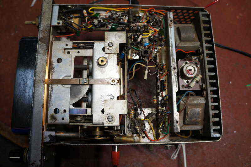
New resistors and capacitors installed.
Tuner Adjustment.
There was nothing left but to adjust the
RF and aerial cores in the tuning unit. AWA gives instructions on how to
do this; referring to a 0.56" gap in a slot in the side of the tuning unit,
as to being the reference point for the initial setting of the tuner. With
the vague alignment instructions, it took a while to work out what they
were referring to (another hour in time here), but eventually I found it.
Suitably set with vernier calipers, the RF and aerial cores were set to
peak up with a 1000Kc/s signal. Fortunately, the oscillator core was spot
on - and so it should be!
This at last did the trick. The aerial
and RF trimmers peaked as they should, and the gain was consistent across
the band. It brought in 2ZB from Wellington, NZ, as it should in the evening.
2GN from Goulburn was receivable late afternoon which is also a good indication.
How the set got so far out of alignment
will remain a mystery, and I can't recall anything like it that I've dealt
with before.
Audio Output Power.
The owner had queried using 4 or 8 ohm
speakers, since 15 ohm types are obsolete. 16 ohm is a good modern equivalent,
but sizes are limited. I assured him it wouldn't damage the set to use
8 ohms, but just that the power output would not be as much as it should
be. Out of curiosity, I thought I'd measure it and make a comparison between
8 and 15 ohm loads.
And here was another mystery. I don't
have the specs for this set, but it does use the same 2N301 output stage
as a number of other sets AWA made. One quoted 3W output. The 966A could
only just manage almost 1W driving 15 ohms. Quite a reduction in power!
But, when I thought about it, there was no way 3W could ever be produced.
With a supply of around 11V across the output transistor, the peak to peak
voltage can never be higher than this. As there is no transformer step
up to the speaker, the speaker will therefore receive this peak to peak
voltage. This is what I measured; 10.8Vp-p, or 3.8Vrms. That equates to
972mW into 15 ohms.
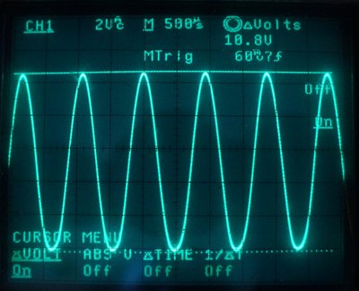
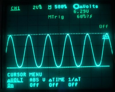
Peak to peak voltage into 15 and 8 ohm loads.
I repeated the test with an 8 ohm load
and the reduction in output power was severe. Now it was 6.29Vp-p, or 2.22Vrms.
That results in the much lower power of 278mW! AWA point out the load impedance
is critical, and they're right.
It's an interesting thought to modify
the output stage to operate an 8 ohm speaker efficiently. The output choke
could be tapped down its winding. Alternatively, the bias could be increased
for the output transistor, provided it could still be driven adequately.
It might be necessary to change the 2N301 for a more powerful silicon transistor.
If the owner cannot get a 15 (or 16) ohm
speaker, I would recommend two 8 ohm speakers in series, correctly phased
of course. I doubt a single 8 ohm speaker will give enough volume with
the car in motion.
Aerial Socket.
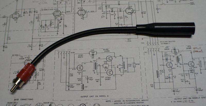
Prior to the Motorola plug being standardised, other types of aerial connector were also in use. Bayonet types were popular, as were microphone connectors. This set uses what looks like an RCA socket. As requested by the owner, an adaptor was made up with an RCA plug connected to a Motorola line socket. I could have simply installed a Motorola socket in place of the original RCA type, but would have detracted from originality. As I discovered, the socket wasn't actually an RCA type at all. It looks like it, and the centre pin fits perfectly, but the diameter of the outer (earth) connection is a fraction smaller. To get a tight connection I soldered a thin piece of brass shim to the inside of the RCA plug.
Just for fun, I tried a 12BA6 and 12BE6
in place of the 12BL6 RF amplifier and the 12AD6. No surprises at all when
the set 'worked' with these common 250V type valves. The 12BA6 worked quite
well, but the 12BE6 less so. Although it oscillated, RF gain was down somewhat.
Some optimisation of the bias would be in order, or alternatively trying
a quantity of 12BE6's to find one with the right characteristics. The point
here is the 12V valves are made so that their curve is uniform at low voltages,
but otherwise they are the same as their 250V counterparts. For the 12V
superhet, the bias had to be optimised for the particular valves used,
and it could well require alteration if any of the valves were to be replaced.
The exception for 12V valves being the
'same' as their 250V counterparts are a few space charge types like the
12K5. These provide sufficient drive to the output transistor. Essentially,
by biassing what is normally the control grid positive, this forces a greater
current flow to occur. The signal is fed into what would normally be the
screen grid. The 966-A does not use this kind of valve; instead another
transistor is used.
From the outside, the 966-A works just
like any other valve set, warming up in the same amount of time. What is
strange is no vibrator buzz - that's probably the most peculiar thing to
get used to.
I have to say I didn't have much enthusiasm
for hybrid sets previously, but having got this one working well, it's
a nice set and works well. The only thing to be wary of is to ensure correct
supply polarity - something that isn't important with a non-synchronous
vibrator set.