The 930A (6 volt) and 931A (12 volt) were
the first of the wedge shaped car radios from AWA. Introduced in the late
1950's, these radios had been specifically designed to sell for 39 guineas
- somewhat cheaper than most other car radios available at the time.
The design of this radio remained largely
unchanged, with several different model numbers, until the last of the
series, the 945AZ (6 volt) and 946AZ (12 volt) in 1965. This was the last
vibrator powered car radio to be manufactured in Australia. Some models
were made to suit particular models of cars, some had tone controls, some
had no internal speaker, and so on. The model names include "Cruiser" "Cruiser
63" "Pressmatic" and "Cruiser 6". The circuit uses 6 valves and a non-synchronous
vibrator. Permeability tubing is used. Where the speaker is fitted, it
is a 5" Jensen design, but made in Australia by MSP (Manufacturer's Special
Products - the component division of AWA).
You can see a 930A/931A (most likely a
931A given it's an English car) operating here at 5'50", and a further
glimpse at 6'27" https://www.youtube.com/watch?v=pKIVZnJMMfg
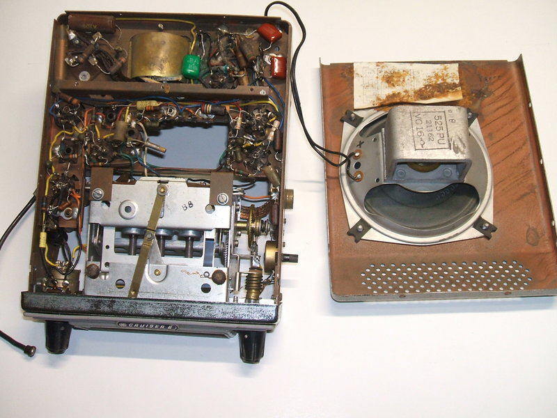
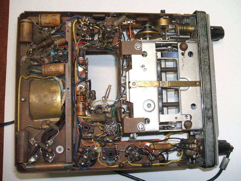
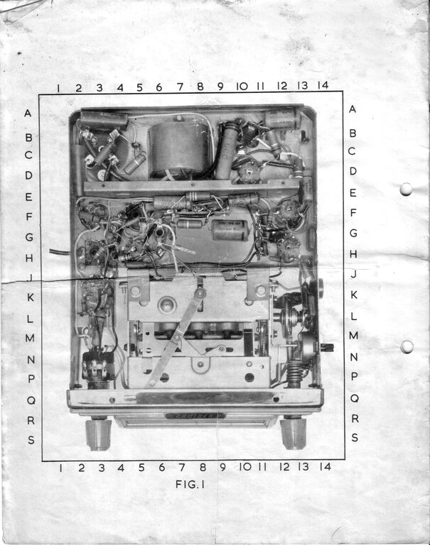
Top side of the chassis contains the resistors and condensers. This
view shows the radio after component replacement. It appears that the adhesive
used for the valve layout label has reacted to cause the corrosion visible
near the speaker.
One version made for VW used a solid state inverter with a 2N301 power transistor instead of the vibrator power supply (942-A / 9943-A / 978-A / 979-A). The same case and chassis was also used for a hybrid set with 12V valves (934-A / 935-A / 936-A /937-A / 937-B). In this model, the transistor audio output stage occupies the space formerly used for the vibrator power supply. The all valve vibrator models were very popular and reliable, and still turn up reasonably frequently. In fact, some examples were seen to be still in use in the 1980's. My first valve car radio was a 946-AZ purchased in 1981 from a wrecker. It was in working order and was used for a few years before replacing the paper condensers.
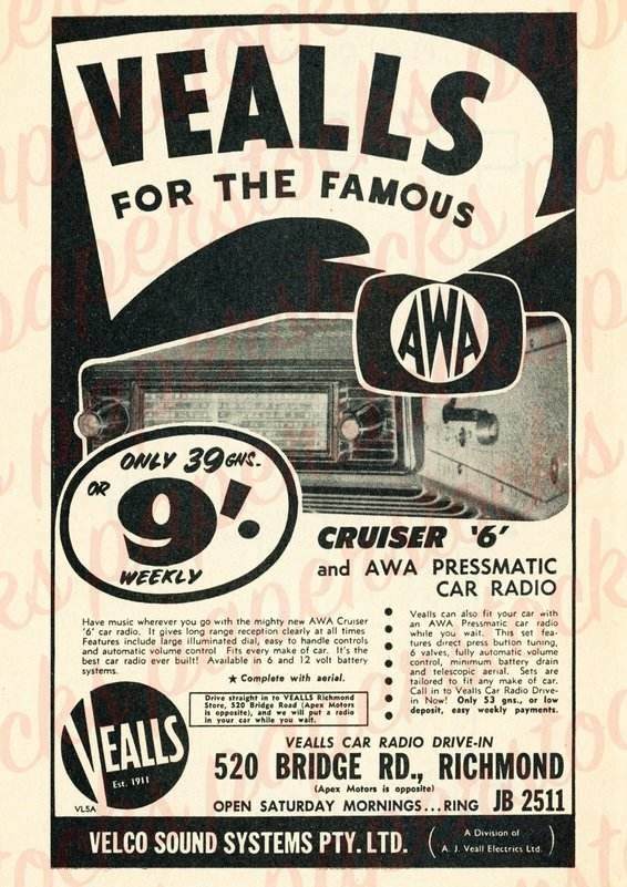
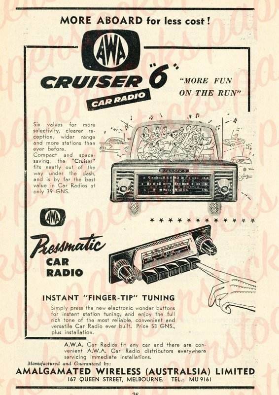
Advertisements for the 930-A / 931-A. The more expensive push-button
version, the 932-A / 933-A is also shown.
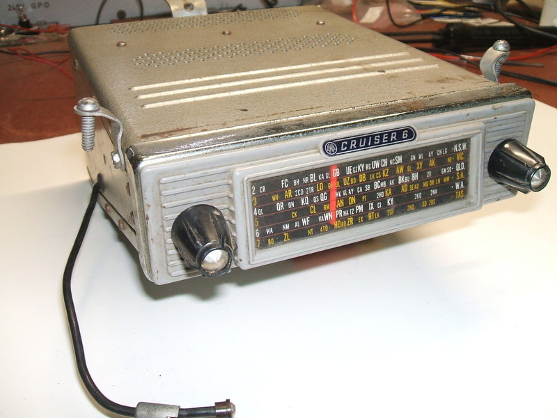
The AWA 930-A.
The radio described in this article is
a 930-A. It was purchased at the HRSA for $15, which is a very typical
price for this model these days. The 930-A is the 6 volt model, and for
12V use is the 931-A. There is a date stamp on the back of these radios,
which states the year and month. It would appear that this particular radio
was made in the 9th week of 1958.
Cosmetic condition was good and the dial
was in excellent condition.
I must admit to connecting it across the
Model
T battery prior to leaving the HRSA - such is the reliability of these
radios that I half expected it to work. The dial lamp lit up, but alas
no action from the vibrator which surprised me a little. As I've mentioned
many times elsewhere on this site, the Oak vibrators used in these sets
are extremely reliable and easy to get going. At this point I just assumed
the contact for the drive coil was dirty, and it would have to wait until
I started work on it at home.
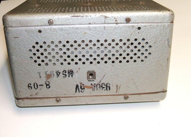
Rear of the 930A.
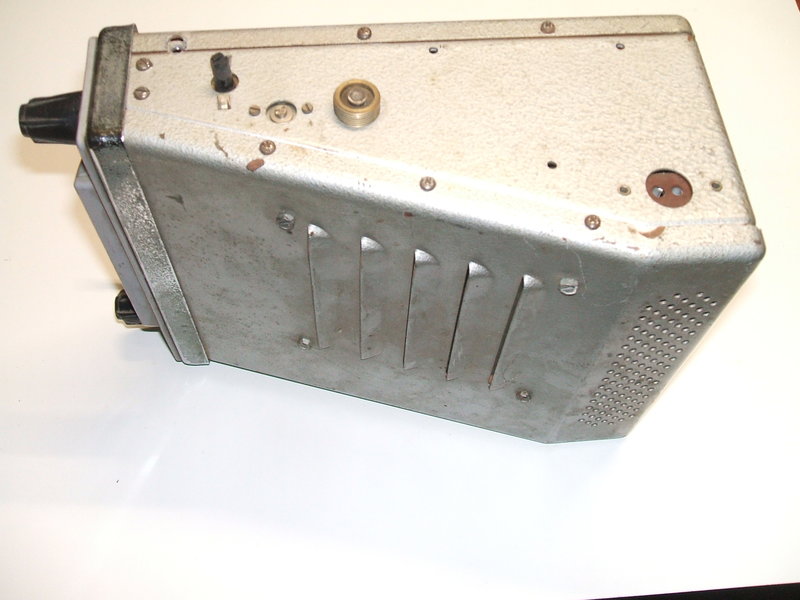
At the side is visible the tone control, aerial trimmer, and aerial
connection. At the rear is the extension speaker socket.
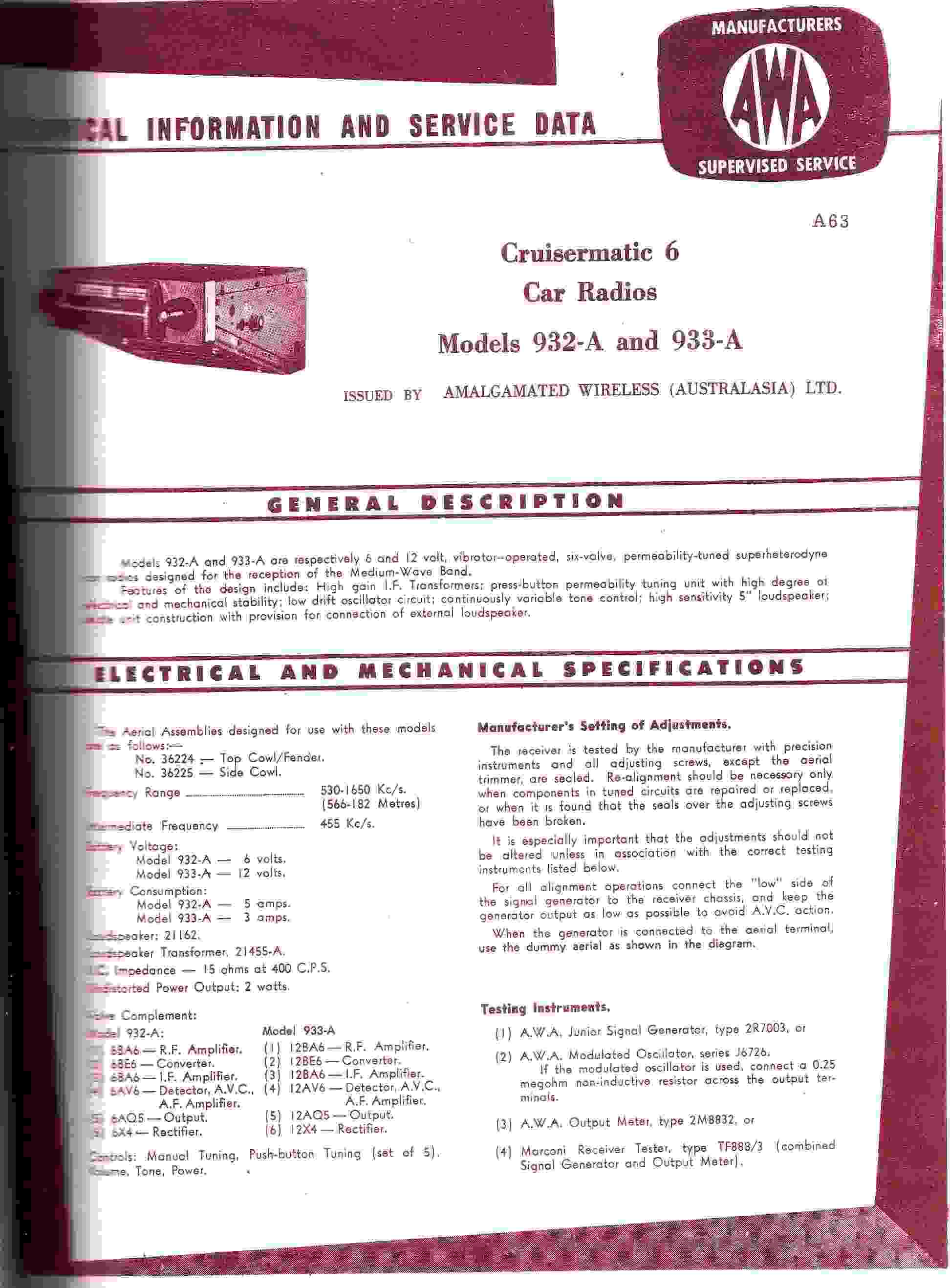
The 932A and 933A are the same as the 930A and 931A but have a push
button tuner.
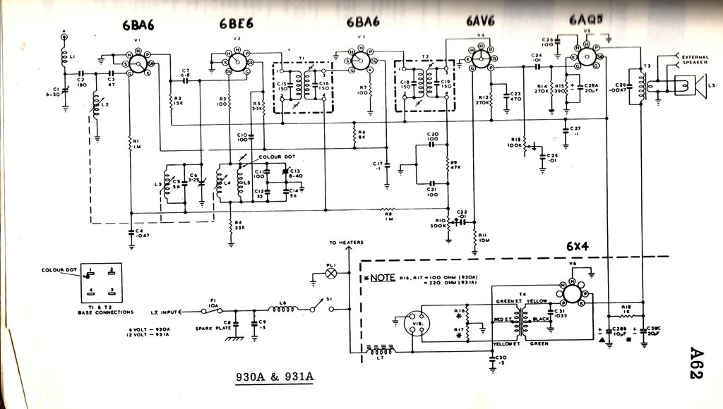
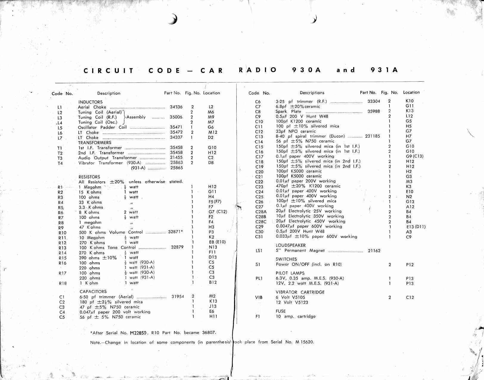
The Circuit.
Not surprisingly, it uses the same American
seven pin miniature valves used in most of AWA's mantel radios during the
late 1950's and 1960's. In fact, apart from the permeability tuning, RF
amplifier, and power supply , the circuit is much the same as a typical
AWA mantel set of the era.
RF Amplifier.
The aerial signal is fed into the first
tuned circuit, L2 and C1/C2. For the purpose of aerial matching, C1 and
C2 act as a capacitive divider which is more convenient than having a tapping
on L2. Furthermore, C1 is adjustable to compensate for slightly different
aerial capacitances. Signal then feeds the grid of the RF amplifier, a
variable-mu pentode, 6BA6. Interestingly, this RF amplifier is RC coupled
to the following stage, the 6BE6 frequency converter. The plate load for
the 6BA6 is a 15K resistor and this is coupled to the 6BE6 input tuned
circuit via a 6.8pF capacitor.
The gain would be less than where a tuned
circuit is used, but this would require a more complicated tuner unit (which
would no doubt push the cost outside of the 39 guinea criteria).
Nevertheless, with the 6BA6 being a fairly
high gain valve, the performance would certainly be a lot better than if
there was no RF amplifier.
Converter.
The frequency converter is a standard
arrangement with a 6BE6 heptode, although the oscillator circuit is modified
to allow for two terminal operation rather than a tapping on the oscillator
coil. Instead of a tapping, screen grid feedback is used via C10. The oscillator
coil (L3) is shunted by L4 which sets the maximum inductance of the tuned
circuit, and the lower limit of oscillation frequency. Upper limit is set
by C13. Thus, with a 455Kc/s IF, the oscillator operates from 985Kc/s to
2105Kc/s, covering the 530Kc/s-1650Kc/s MW broadcast band. A grid stopper
resistor R3 is included for oscillator stability.
The input signal of the received station
feeds into the 6BE6 third grid in the usual way, have been preselected
by the tuned circuit consisting of L3 and C5/C6. At the plate, the 455Kc/s
IF is available and coupled to the next stage by T1.
IF Amplifier & Detector.
Another 6BA6 functions as the IF amplifier,
tuned to 455Kc/s by virtue of the double tuned IF transformers, T1 and
T2. The cathode bias resistor is unbypassed to ensure stability, given
the high gain of the circuit. From the IF amplifier, the 455Kc/s AM signal
is demodulated by one of the diodes of the 6AV6. The remnant IF component
is filtered out by the low pass filter, C20, R9, and C21. Here, there is
clean audio superimposed upon a negative going DC voltage. This DC increases
with signal strength and so provides the AVC voltage, via the filter consisting
of R8 (1M) and C4 (.047uF). This filter has a sufficient time constant
to remove the audio, leaving just a voltage dependent on signal strength.
The AVC controls the RF and IF amplifier stages. It is for this reason
that variable-mu (remote cut-off) valves are used for these stages. Sharp
cut-off valves like the 6AU6 would only allow limited control, and could
cause intermodulation distortion with strong signals. It is important to
note that with a car radio, good AVC is more important than with a domestic
receiver, because of the considerable variation in signal strength as the
car is driven from one place to another.
Audio Amplifier & Output.
As well as feeding the AVC circuit, the
demodulated signal feeds the volume control, which also provides the detector
load. From the wiper of the volume control, the signal is amplified by
the 6AV6 triode. This triode uses contact bias by virtue of the 10M grid
resistor. This is a common scheme used with high-mu triodes which handle
a low level input signal. Basically, the grid being in proximity to the
cathode picks up electrons and therefore develops a negative charge. If
there was no grid resistor, the triode may accumulate sufficient charge
to cut off, and that would result in a rather distorted signal. If the
grid resistor is too small, the charge leaks away too fast, and insufficient
bias is developed. Generally, 10M is the most commonly used value of grid
resistance, but values between 4.7M and 22M have also been used. Contact
bias is convenient where it can be used, because it eliminates the cathode
resistor and bypass condenser that would otherwise be required.
At the plate of the 6AV6, the audio signal
is a good deal stronger, being in the tens of volts peak to peak, and is
further filtered from any remaining IF by the bypass condenser C23.
This feeds the power output valve, a 6AQ5
beam tetrode. A simple top cut tone control is also provided by C25 and
R13. As R13 is adjusted to a lower resistance, C25 is brought closer into
the 6AV6 plate circuit, progressively shunting the high frequency audio
signals to earth.
The 6AQ5 plate load is the usual output
transformer, which then feeds the 16 ohm speaker. A two pin socket allows
connection of an extension speaker in parallel. Of course, the impedance
matching is upset if an extension speaker is used, but in practice the
scheme works well enough. The 6AQ5 uses cathode bias provided by a 390R
resistor. This is bypassed by C28A.
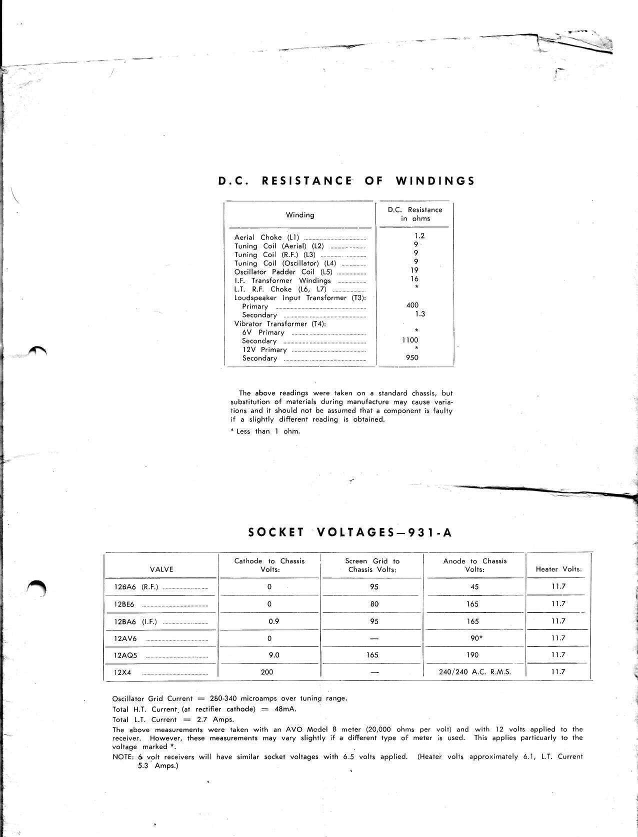
Power Supply.
Turning now to the power supply, this
is based around an Oak V5101
non-synchronous vibrator. Oak vibrators were under licence in Australia
by MSP. The power transformer is of a style common to other AWA equipment,
but obviously designed here to work with a 6V vibrator circuit. The secondary
of the transformer feeds a 6X4 rectifier in the usual way, and the resultant
DC (200V) is fed directly to the speaker transformer, and via an RC filter
(C28B, R19, C28C) to the other stages of the receiver. A further filter
(R6/C17) provides correct voltage for the RF, converter, and IF screen
grids. All three electrolytic condensers C28A, C28B, C28C share the same
can.
Unlike most vibrator power supplies using
a centre-tapped secondary, AWA have connected the buffer capacitance (C31)
across only half the secondary. The advantage of this is considerably less
voltage stress across this component. In fact, an ordinary 600V paper type
is used.
There are primary damping resistors across
the vibrator contacts, each of 100 ohms (R17/R18). These further remove
any RFI as well as making things easier for the vibrator contacts. For
the 12V model, these resistors are shown as 220 ohms. It is interesting
to note that in subsequent models, that for the 12V version these resistors
were increased to 330 ohms. Presumably, 220 ohms got just a little too
hot, hence the revision.
6 or 12V.
Most other car radios had the valve heaters
rewired into a series parallel circuit for their 12V versions. The AWA
radios of this era took a more elegant approach and simply used valves
with 12.6V heaters; e.g. 12AQ5 instead of 6AQ5. Regardless of the heater
circuit, the power transformer has to be changed for a 12V version. While
the vibrator could have a resistor in series with the driving coil to allow
12V operation, it is simpler (and slightly more efficient) to substitute
a vibrator with a 12V coil (e.g. V5123). The dial lamp of course, is simply
substituted with one of suitable voltage.
The low tension supply is fed into the
set through a fuse then passes through a spark plate to remove ignition
interference that may be present on the supply. Further interference reduction
is performed by L6 before feeding the valve heaters. Vibrator interference
is prevented from radiating through the 6V supply by means of C30 and L7.
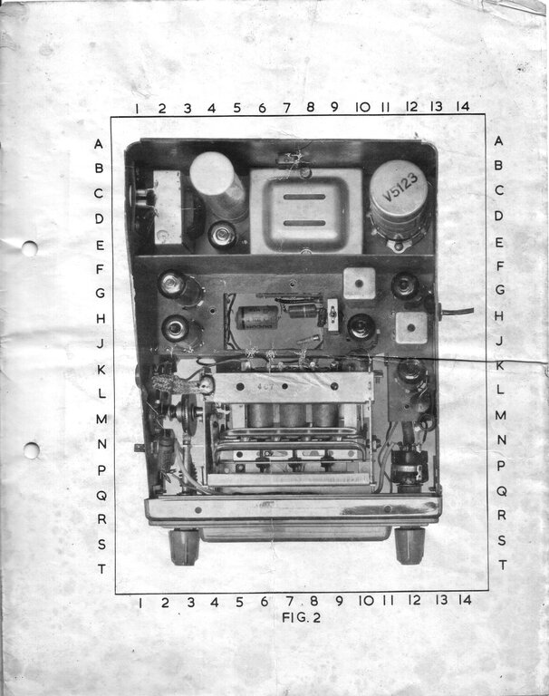
Shielding is important in car radio design,
and to this end, the vibrator, transformer, and rectifier are mounted in
a separate compartment in the rear of the set. Multiple screws ensure a
good connection between the lids and the case.
Parts were all original.
It was not at all surprising to see all
the parts original. From 37 years of experience with this series of AWA
car radios, I knew them to be very reliable. In fact, I would say the most
reliable and best designed of all the valve car radios I have encountered.
However, I did notice that the power transformer had been dripping wax.
Either some fault had caused the transformer to run hot, or the radio had
been in a very hot car for a long time. The knobs and dial were in excellent
condition. The plastic of these deteriorates in strong sunlight, and as
these were in excellent condition I tended to think more of the lines of
an electrical overload being the cause of the wax dripping.
There was some corrosion under where the
valve layout label had been glued to the bottom lid where the speaker is
mounted. There was no evidence of any liquid having entered the radio,
and there were no electrolytic capacitors nearby which could expel their
corrosive electrolyte. Presumably, something was in the adhesive to cause
this reaction. The label was damaged, but as I have plenty of these radios,
it would be easy enough to make a copy of a good one.
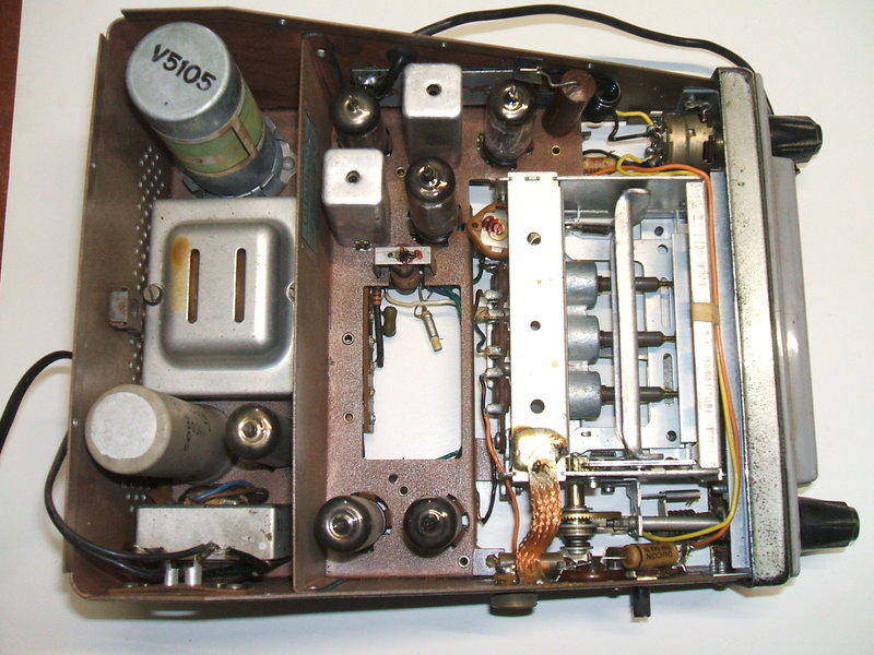
Very clean and untouched inside. Note the wax on the power transformer.
I decided to approach things a little differently with the restoration of this set. Rather than simply replace all the known problem components and then test it, I decided to replace each part one by one, testing the radio as I went. I thought I'd do this in view of this article, just to demonstrate the problems of paper capacitors and why they must be replaced - even if sound issues forth from the radio from the start.
The Vibrator.
Connecting the vibrator up to a 6V power
supply didn't get it started, but I could feel the reed swinging. For some
reason the drive contact wasn't opening as the reed swung over. The can
would have to come off - an easy procedure with the Oak design. The reason
was clear; the power contacts were gummed up which prevented the reed swinging
over its normal arc. The material on the contacts was some kind of hardened
rubber which I presume to have migrated from the flexible base and support
cap for the drive coil - both made of very flexible sponge rubber. Probed
with a sharp knife, it all flaked off the contacts easily, and the vibrator
looked like new.
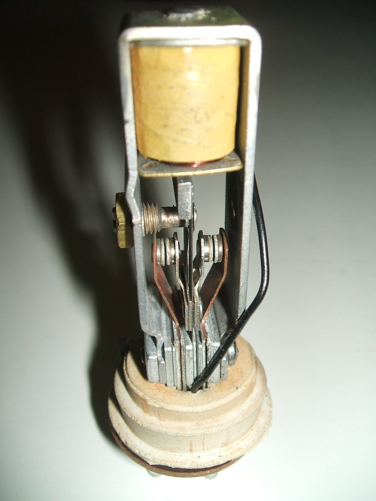
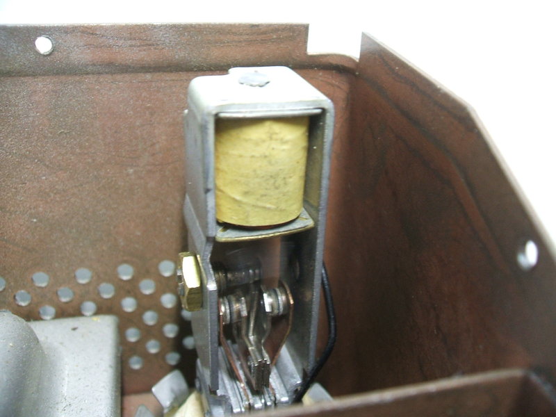
Looks like new doesn't it? It just goes to show that with a proper
design, vibrator deterioration is a non-issue.
There was absolutely nothing in the way
of black deposits in the can or over any of the parts. The contacts showed
no visible signs of erosion. In short, it looked like a N.O.S. vibrator
straight out of the box. Once again, we see that when a vibrator power
supply is correctly designed, and correctly loaded, that with a well designed
vibrator such as the Oak, vibrator life is a complete non-issue. I was
not surprised actually, because I have come to expect this with this series
of AWA radios. If you want an example of a "perfect" vibrator power supply,
then look no further than this AWA design. This is yet another of these
radios to confirm that AWA got it right.
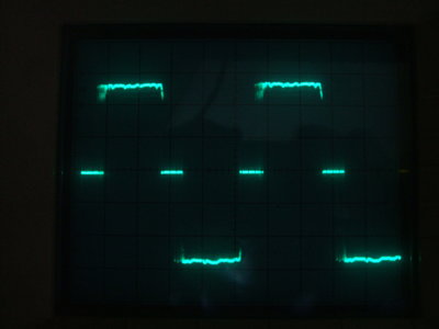
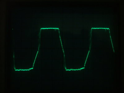
Vibrator waveforms for a resistive load and across the transformer
primary.
Once cleaned, the vibrator was able to
start. One of the contacts provided the perfect 4ms duty cycle - obviously
no wear. The other contact, however, did need a slight adjustment as it
had only a 3.3ms duty cycle. It would have worked as is, but for efficiency,
it's better to have both contacts with the same duty cycle, not only to
provide correct B+, but also to eliminate DC saturation of the transformer.
So, a little tweak of the monel metal side contact, and the vibrator was
back to "like new". I would say that the contact had simply shifted slightly
after years of being hammered by the vibrating contacts.
No complaints for something 60 years old!
Just to confirm, no sparking evident. That's to be expected with
these AWA car radios.
Installed back in the radio, no sparking was visible, which again is what I expect. Music issued forth for a couple of minutes, until the expected distortion set in. Now it was time to start component replacement.
Of course, the distortion was from the
6AQ5 grid coupler being leaky. Grid voltage was about +12.5 above earth.
With the voltage dropped across the cathode resistor, the 6AQ5 was operating
with virtually no bias. In fact, current on the 6V supply input dropped
about 1A when the grid was shorted to earth. Replacing this capacitor fixed
this problem.
A check of the 270K grid resistor showed
it to be 367K. While this value was not critical, it is better to have
it lower than higher in this application. Power output valves in car radios
are especially at risk from grid emission, because of the higher cathode
temperature when the battery is charging, and the hot environment that
car radios often operate in.
This is why the grid resistor here is
270K and not the usual 470K or 1M. The fact that the grid resistor had
already gone 100K high meant that it might keep going high. Best to replace
it and never worry about it again.
Next, a couple of minutes later, the input
current went up to about 8A. No surprises for guessing this one; the .033uF
buffer condenser. Normally, I recommend against powering up a vibrator
power supply unless the buffer condenser has been replaced, but I was watching
the current and was ready to switch off. I hate to think of all the valve
car radios dragged out of storage after years and powered up by people
unfamiliar with vibrator power supplies. Connected to a car battery with
no fuse and no ammeter in series, there will be no warning for when things
go bad and the vibrator risks being damaged. The recommended 10A fuse is
too high for my liking. While it protects against short circuits, it won't
do much to protect the vibrator and transformer under fault conditions
like this. I would prefer 6-7A for the 6V model, and 4-5A for the 12V model.
Once the buffer condenser was replaced,
current was normal and it was now safe to run the radio. B+ at the 6X4
cathode was the specified 200V.
Next paper condenser to look at was that in series with the tone control. Any leakage here will drag down the 6AV6 plate voltage. I measured it a 55-60V depending on the tone control setting. When this was replaced, the plate voltage was now 72V. There was one more capacitor in the 6AV6 circuit to deal with, and that's the grid coupler. Replacing this raised the plate voltage to 75V. Had the design of the radio been such that the tone control was across the 6AQ5 grid resistor, leakage of the series capacitor would have, ironically, been a good thing - reducing the overall grid resistance, and the possibility of grid emission.
The AVC circuit is high impedance, and any leakage in the filter would reduce the control. Therefore, this capacitor was replaced next.
There are two .1uF's bypassing the B+ supplies. These, if they became too leaky, would overload the power supply. In fact one had bubbled wax on its surface which suggests exactly this. Once replaced, there was only one other wax dipped paper condenser left, and that was the 6AQ5 plate bypass. However, the way it is connected, between B+ and plate, means any leakage will not harm anything. The DC across this capacitor is normally quite low as it is connected directly across the speaker transformer winding. Had it been connected from plate to earth, it would have been essential to replace it. There are two AEE Microcap paper condensers in the 6V circuit. These were left since any leakage cannot cause harm, and any leakage current will be insignificant at 6V anyway.
With the 6AQ5 having drawn excess current for who knows how long, I wondered about its cathode resistor and if it was still OK. It looked a little overheated, and when checked, sure enough, the original 390 ohms was found to be 746 ohms. Once replaced, normal power output could be obtained.
All the paper condensers were checked on a Megger. All of them showed under 200K leakage. No wonder the power transformer had run warmer than it should.
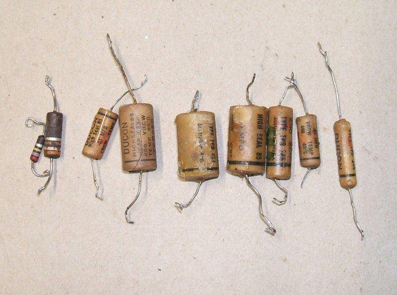
The replaced components. All the condensers measured less than 200K
with 500V.

There is no doubt that the 930-A and subsequent vibrator sets are a perfect example of how to design a car radio correctly. No vibrator interference, and a virtually unlimited vibrator life demonstrate correct power supply design. There is a 'no-nonsense' feel about the design too; nothing that's not required is included, which of course increases reliability. Serviceability is excellent with everything accessible, and the layout is neat and uncluttered. Ultimately of course, the performance is excellent with regards to sensitivity, selectivity, and sound quality. It seems to be an Australian thing to do, but operating car radios with a B+ 150-200V means less current drain than with sets operating with a 250V B+. The difference in power output is hardly noticeable, yet the greater economy in supply current is worthwhile.