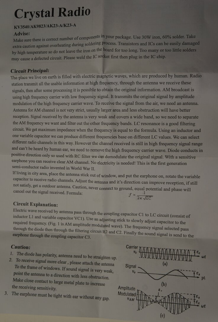
The basic method of AM reception and demodulation.
There must have been thousands of articles
in magazines and books on how to construct a crystal receiver. For many
electronics enthusiasts, a crystal set was their first introduction to
radio receiver construction. It is as simple as one can get, with only
a few components required, and costs nothing to run, since it is powered
entirely from the signal picked up by the aerial.
The basic method of AM reception and demodulation.
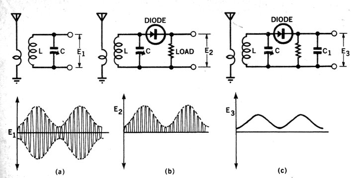
To begin with, a description of AM reception
and demodulation is in order. Referring first to diagram (a), the inductance
of the coil L and the capacitance of the tuning capacitor, C, form a parallel
resonant circuit. Either L or C can be altered to select the resonant frequency.
Since this is a parallel resonant circuit,
the impedance is highest at the resonant frequency. The signal received
from the aerial is coupled into the coil by another winding, which is placed
close to the coil L, so that magnetic coupling takes place.
The end result is that the circuit presents
a low impedance to all but the signal at the resonant frequency. The RF
carrier of the selected station, modulated by the audio signal, appears
as E1 across the resonant circuit.
In a reasonable signal area, E1 might be
around 500mV. While this is sufficient to drive a set of headphones, the
signal is inaudible because it is still at RF (Radio Frequency). Humans
can hear up to about 20kHz, so it can be imagined there is no chance of
hearing a signal at 1MHz, which is in the middle of the AM broadcast band.
No normal speaker or headphones could respond to that kind of frequency
anyway.
However, the RF is modulated by the audio
program, and it is a simple matter to extract that part from the signal.
Referring to diagram (b), a diode is introduced into the circuit. This
passes only the positive going part of the RF waveform. While the RF (e.g.
1MHz) is still present, it is only of one polarity which happens to also
contain the modulating (audio) signal.
At this point, one might say that the
waveform in diagram (a) also contains the modulating signal. Yes it does,
but since there is also a negative going signal of the same amplitude as
the positive going signal, the average of the modulating signal is zero.
Finally, the RF is removed from the modulating
signal by means of a filter capacitor, as shown in diagram (c). This smoothes
out the audio waveform by averaging out the high frequency RF pulses that
make it up. If we connect headphones at point E3, the program will be heard.
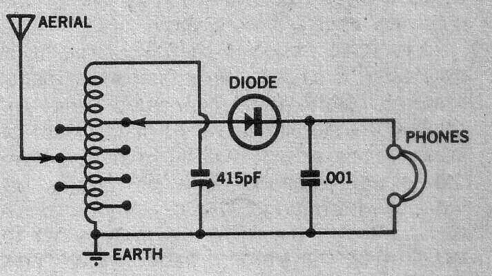
The circuit in diagram (c) can actually
be used as a crystal set, but some improvements can be made as follows:
Circuit of a practical crystal set.
Detector Loading.
Unfortunately, connecting anything besides
the L and C to the tuned circuit loads it down, reducing performance. The
loading of the headphones effectively places a low resistance in parallel
with the tuned circuit, which reduces the Q (Quality factor). The effect
of this is that
the bandwidth of the tuned circuit increases,
reducing selectivity. That is, the ability to separate stations is reduced.
By connecting the detector circuit to
a tapping further down the coil, the loading effect is reduced, since the
coil sees less of the loading resistance. Selectivity is improved, but
the catch is that now the voltage fed into the detector is also reduced.
Ultimately, a compromise has to be made
- a loud signal with less ability to separate stations, or a better ability
to separate stations, but with less volume. This is going to depend on
the locality in which the set is used; what the signal strengths of the
stations are, and how far apart in frequency they are. The ideal situation
is in a location with only one station. Selectivity is of little importance,
and the detector can be connected across the whole coil.
Aerial Loading.
As well as the detector circuit loading
down the coil, so does the aerial. Again, feeding the aerial into a lower
tapping reduces the loading effect, but doing this also introduces less
signal into the tuned circuit. Once again, a compromise has to be made.
Generally, a longer aerial works best with a low tapping, and a short aerial
with a high tapping. As before, if there is only one station, a long aerial
connected across the entire coil will provide the best signal.
A long wire aerial has a certain amount
of capacitance, and connected across the coil it can be imagined that this
capacitance adds to that of the tuning capacitor. Thus, an excessively
long aerial can restrict the tuning range, and is another reason to use
a lower tapping.
In fact, some crystal set designs have
no tuning capacitor, relying entirely on aerial capacitance. In this instance,
since the capacitance is now fixed, the coil has to be adjustable to select
the required frequency.
More elaborate (and selective) crystal
sets have more than one tuned circuit, and provide for better aerial matching.
The Diode.
The choice of diode is important because
there is only the signal voltage to forward bias it. For example, a silicon
diode such as the 1N914 needs about 600mV. For this reason, most crystal
sets use germanium diodes, such as the OA90 or 1N34 which require about
250mV bias voltage. Schottky diodes with their 400mV bias voltage have
also been used, and one such receiver is described below. If a bias circuit
is provided, silicon diodes can be used, but this gets away from the 'free
power' aspect.
The basic AM detector circuit can also
be used for FM, if it is tuned slightly off frequency so that slope detection
occurs. This is described further in the numerous super-regenerative receiver
articles elsewhere on this site. VHF FM crystal sets do exist, and designs
can be found on the internet.
Single sideband suppressed carrier (SSB),
or continuous wave (CW) transmissions cannot, unfortunately, be received
by the basic AM detector circuit. In the case of SSB, there is no separate
RF carrier as such. Modulation is heard, but is unintelligible. In the
case of CW, the carrier is not modulated, resulting in no audio output.
My First Attempt at a Crystal Set.
My first interest in crystal sets was
in 1976. As part of a larger article on radio in the World Book Encyclopaedia,
there was a description of how to build a crystal radio. It was a very
basic design using slider tuning to adjust coil inductance. Attempting
to construct it was also my first introduction to Dick Smith Electronics,
which was to become a very well known chain of electronics stores, located
a few suburbs away. I needed copper wire, a diode, and an earphone.
Unfortunately, it didn't work, and never
could have with the way I'd constructed it. To start with, I didn't know
the enamel had to be stripped off the copper wire, so effectively the whole
thing was just a great big open circuit. The World Book article showed
the earphone as being half of a set of high impedance headphones. There
was nothing like that at DSE, but there was a similar resemblance to a
pillow speaker which they had. Unbeknown to me at the time, its 8 ohm impedance
was totally unsuitable.
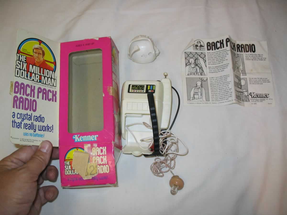
Six Million Dollar Man crystal radio. Pics from eBay since I no
longer have the original.
It was actually a very good performer at my location, which was then 13km from the 5kW commercial transmitters in Sydney. It used the same design as the now highly collectible Rocket Radios. Adjusting the telescopic "aerial" on the top of the backpack moved a ferrite slug in and out of the coil former, on which the circuit was constructed. In other words, it used permeability tuning. The earphone was the usual crystal type, which could be stowed in the compartment within the backpack. Also attached was a clip lead, to be connected to a suitable object to function as the aerial. It worked well connected to a down pipe, and also the frame of an electric radiator. Eventually, the ferrite slug fractured where the telescopic "aerial" had been attached to the end of it. So that was the end of it. The parts were later used in other projects.
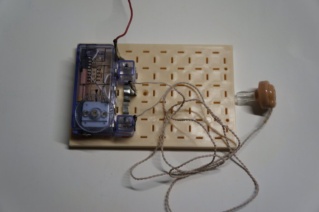
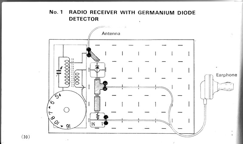
Crystal set project from the Denshi Block SR-2A and SR-3A electronic
kits.
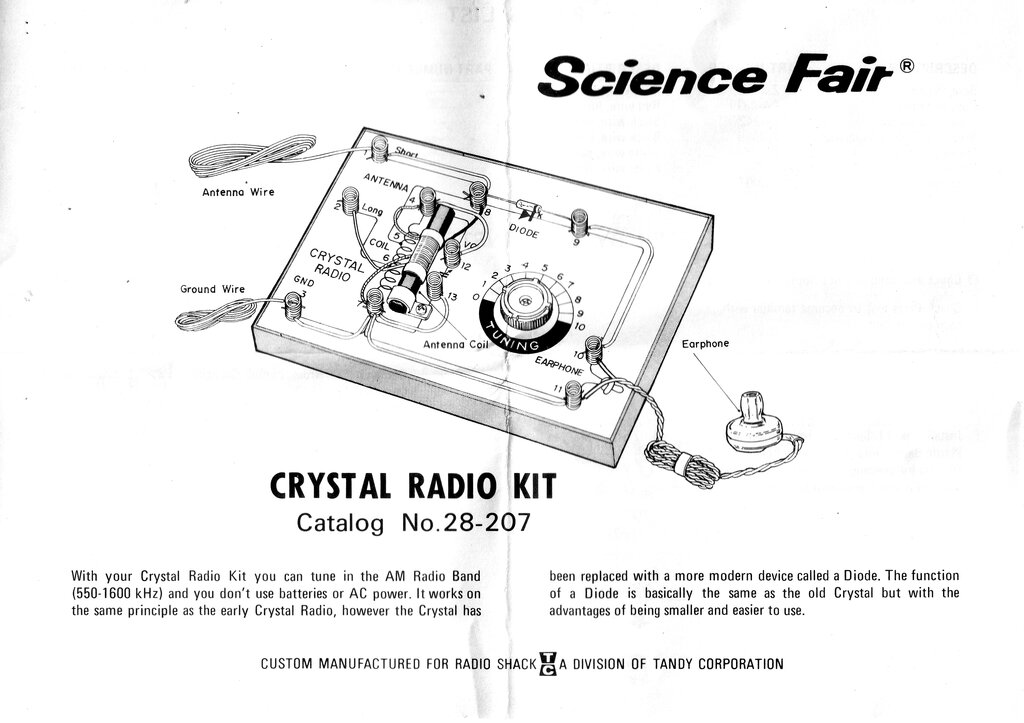
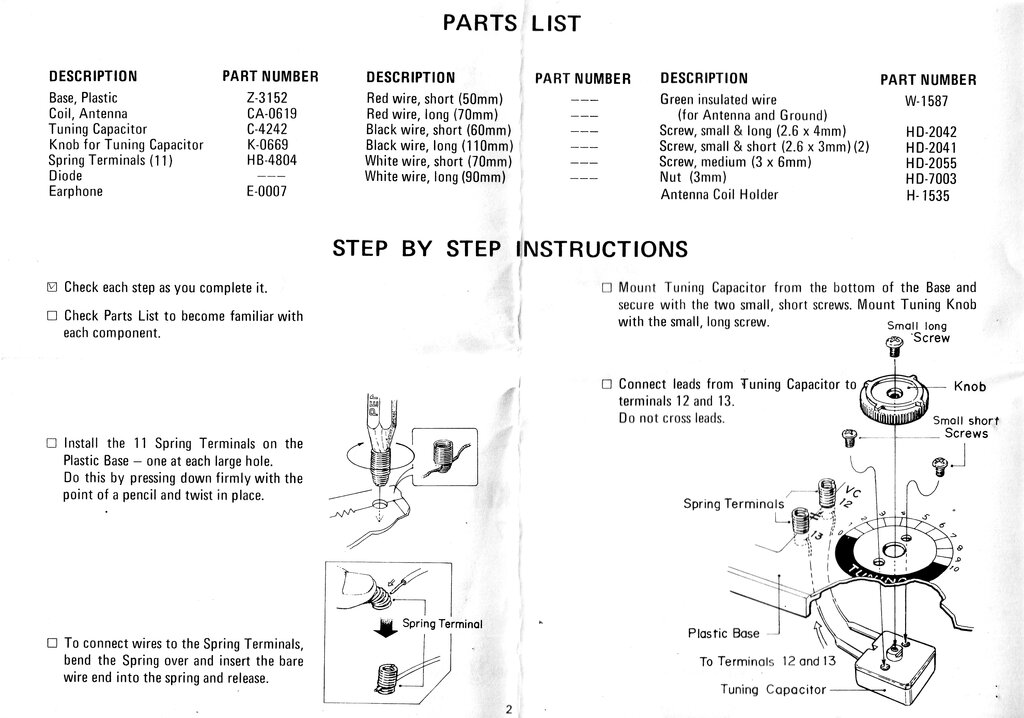
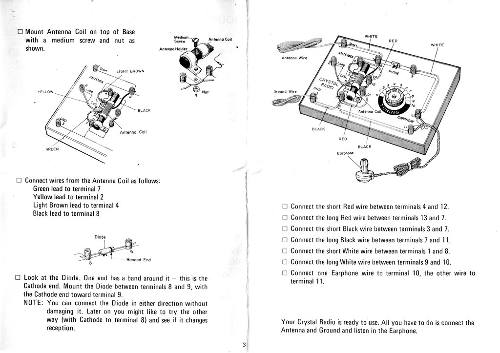
Science Fair 28-207 Crystal Radio
Kit.
Around the same time, a school friend
had a crystal radio kit that was being sold by Tandy (U.S. readers will
know this company as Radio Shack). I wanted one of these too, and in due
course one appeared for Xmas of 1977.
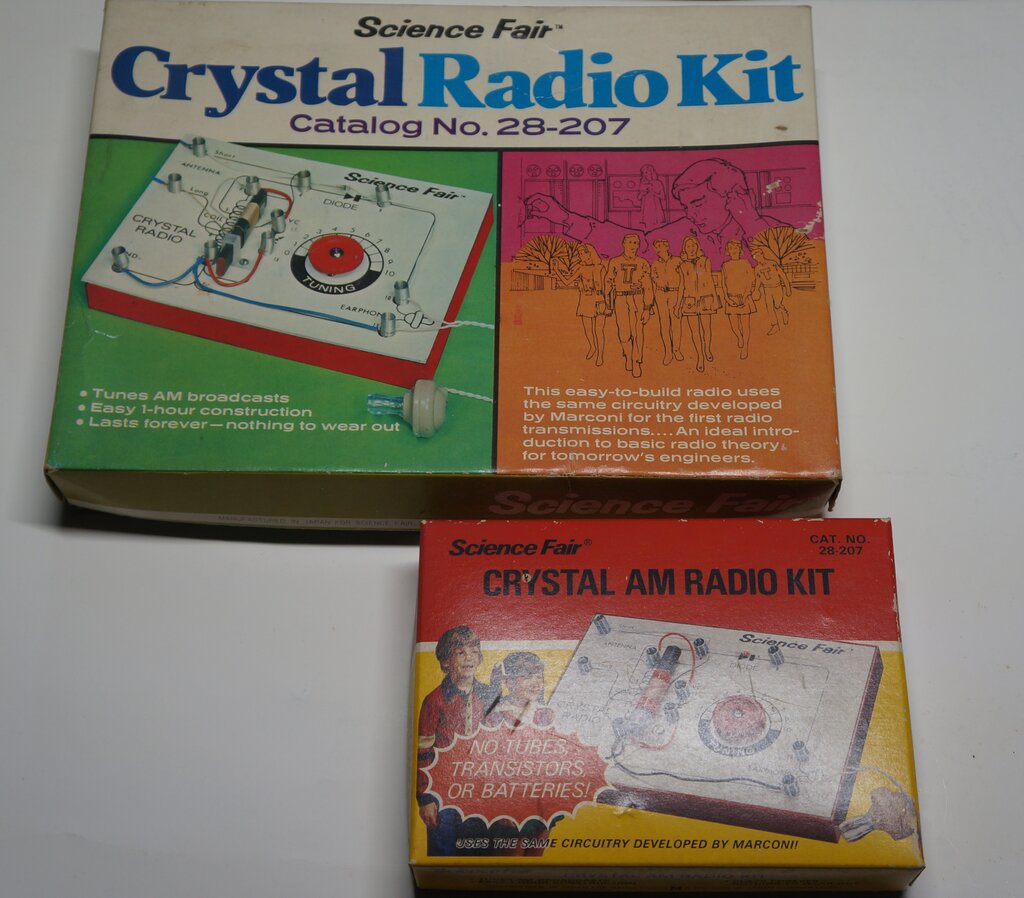
This kit had been sold by Tandy for many years. These are two different
styles of packaging. "...uses the same circuitry developed by Marconi..."
is pushing the truth a bit.
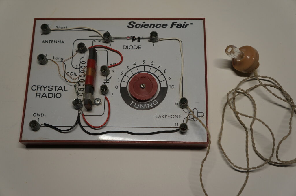
Basic, but a good performer.
I used this set for quite a few years and it worked well, but pulled it apart when I was still young and naive. I've since replaced it with three from eBay; one which is still in a sealed box.
Home Made Crystal Set and Wavetrap.
Crystal set at left; wavetrap at right.
The Crystal Set.
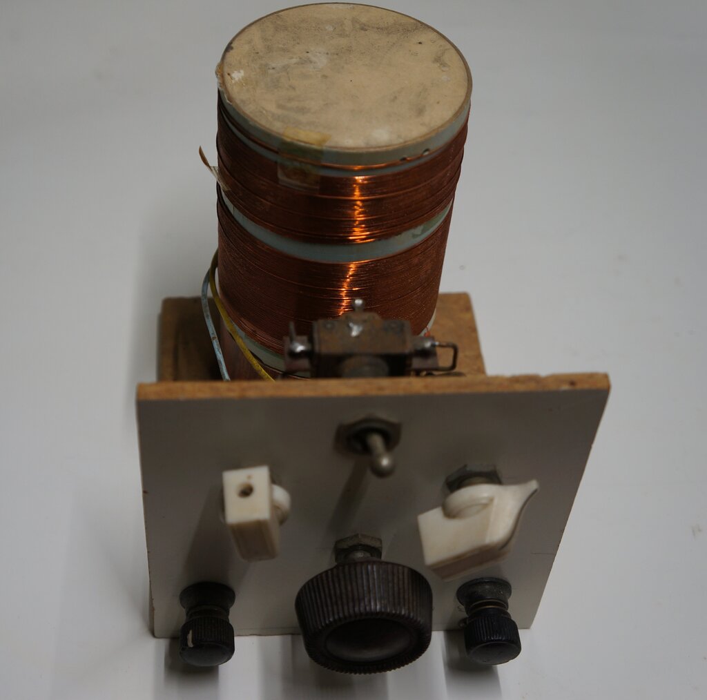
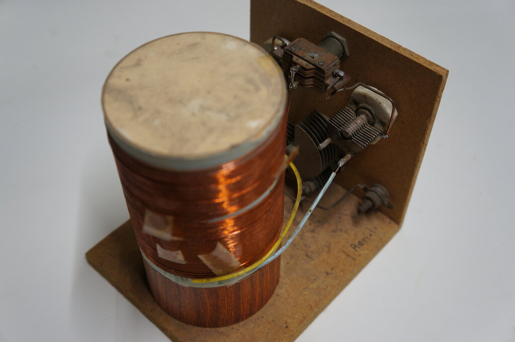
Rear view of crystal set and wavetrap.
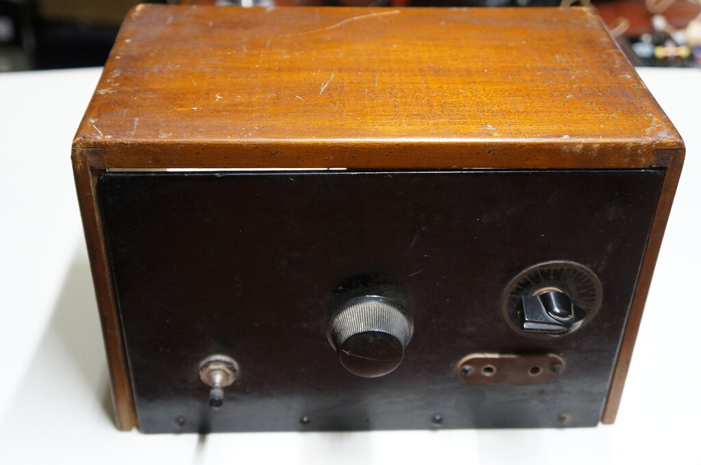
The crystal set looked of 1950's vintage,
made from scraps of wood. It has a commercially made cardboard coil former,
and the coil is wound in enamelled copper wire. Five tappings are provided
along the winding, which are connected to a rotary switch, and thence to
the aerial.
The switch has more positions than necessary,
so the redundant ones have been bridged out. This set required a bit of
work to get going. There's not a lot to go wrong, but a combination of
things prevented anything being heard at first. It was found the earthy
end of the coil winding was not connected, with the wire having broken
off a tag, which also functions as one of the mounting feet for the coil.
With that fixed, there was still no signal. A signal generator outputting
several hundred millivolts did reveal a faint signal, but only well below
the broadcast band at around 100kHz. Despite the coil tappings, the loading
of the signal generator was sufficient to detune the set. Inserting capacitance
of about 400pF, in series with the aerial connection then allowed the ABC
transmitters on 576kHz and 702kHz to be very faintly heard. Compared to
the Science Fair crystal set, this was unusable. Ultimately, it was found
that the diode was faulty. Replacing it with a similarly aged 0A81 brought
up the volume to what would be expected.
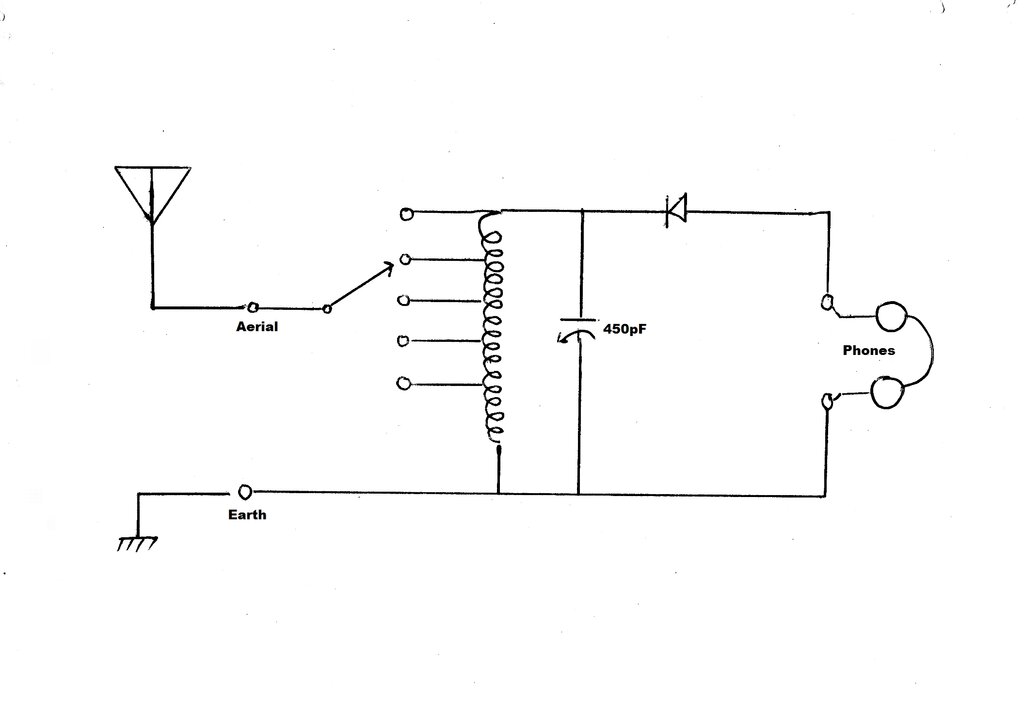
Circuit of the crystal set.
The circuit of this crystal set is very basic, but does have a tapped aerial coil. Simple designs have a clip lead to connect the required tapping, but here a rotary switch is used instead.
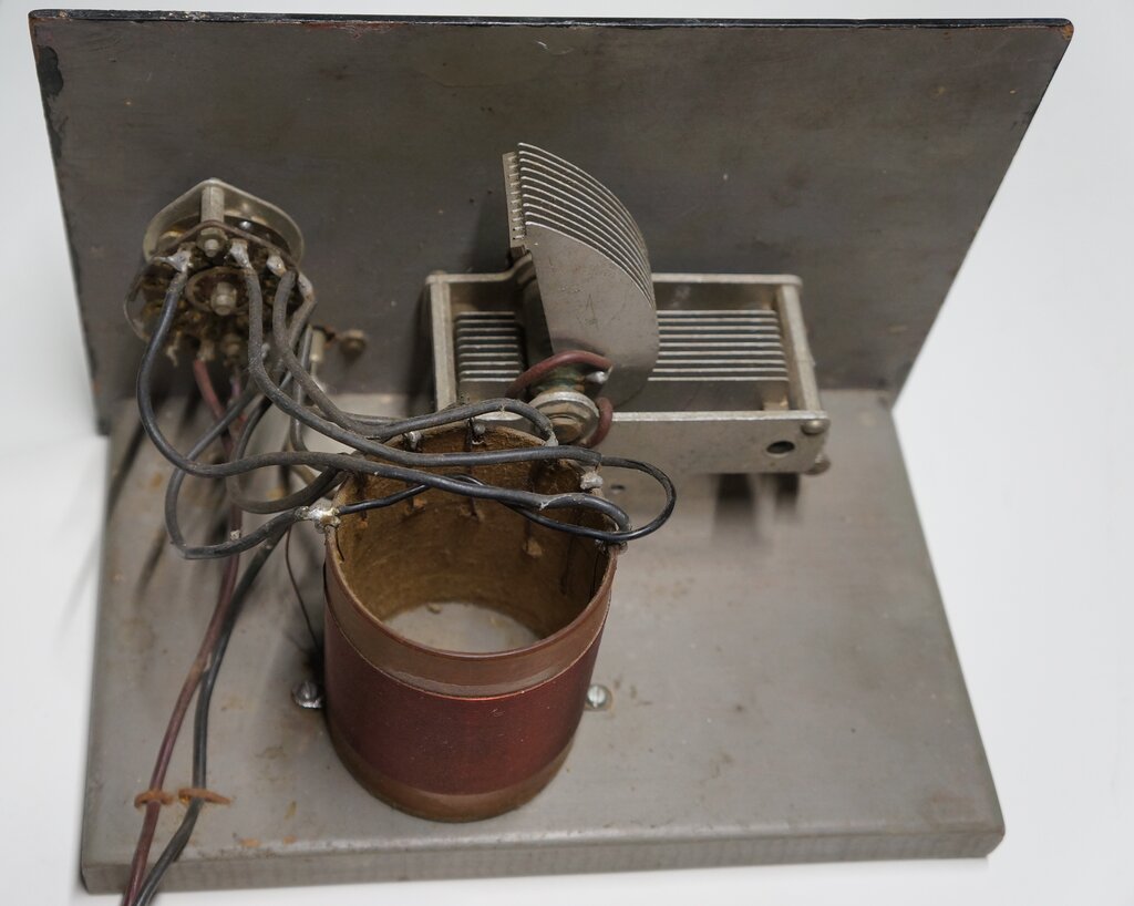
The Wavetrap.
Since my location is so distant from the
transmitters, a wavetrap is not required, but it was connected into the
aerial circuit of the crystal set to see its effect. It was minimal, but
adjusting the knobs could strengthen and weaken the signal.
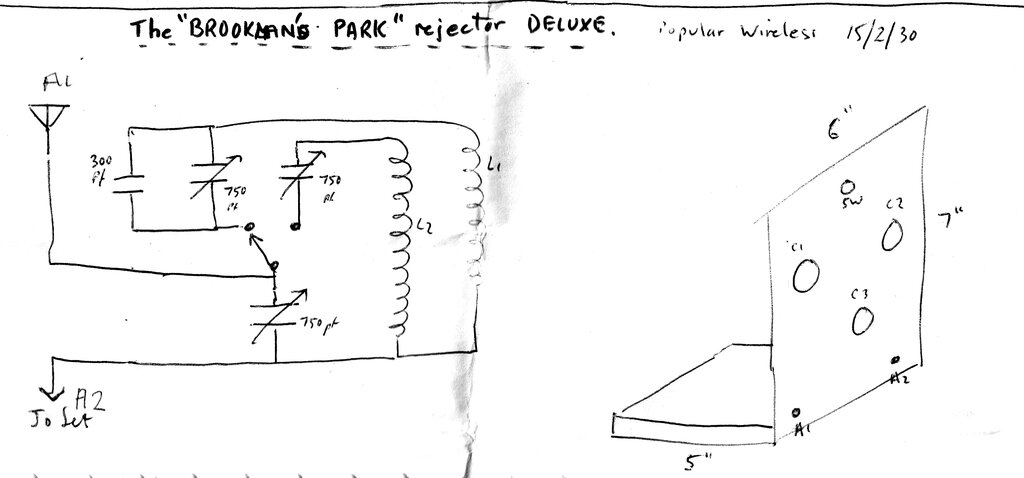
Constructional notes for the wavetrap. The capacitor values are
different in the version described. The 300pF is not present, and the variable
capacitors are closer to 100pF.
With the crystal set and wavetrap came
some hand drawn diagrams. Someone was obviously interested in crystal sets
and 'rejectors' (wavetraps), as presented in the English "Popular Wireless"
magazine around 1929-1930. None of the diagrams matched the crystal set,
but the wavetrap was very close to the diagram shown above. A point of
difference is that all three variable condensers on the home made construction
are far less than the 750pF specified. They are more likely to be 100pF.
Also, the 300pF fixed capacitor is not present.
Unfortunately, the particular issues of
Popular Wireless are not available on World
Radio History, so the thoughts behind its design are not clear. From
other issues around the time, it seems this is when the Brookman's Park
transmitter was set up, and there were concerns that because it was transmitting
on two different wavelengths, there would be interference between the two.
Thus, a wavetrap might be required in some locations. [As a side note,
Brookman's Park is where the 30
line Baird television signals were transmitted from until 1935.]
At first glance, the circuit seems contradictory
to what is required. It looks like there are two series resonant circuits,
no doubt for each of the two Brookman's Park frequencies. One of these
is selected by a two way switch, and placed in series with the aerial connection
to the receiver. Across the whole circuit is another variable condenser.
The important characteristic of a series
resonant circuit is that it presents a low impedance at the resonant frequency.
Normally, a wavetrap is a parallel tuned circuit, which presents a high
impedance in series with the aerial connection of the receiver. The tuned
circuit is therefore adjusted to resonate at the frequency of the interfering
station.
However, looking at the circuit in a different way, we can see that it is actually a parallel resonant circuit. Ignore the A1 aerial connection, and consider that the lower variable condenser is always in series with one of the upper condensers, and then placed across the coil. The fact that the aerial is fed into the mid point capacitor connection, rather than the end of the required coil, would appear to be some kind of matching arrangement. One could surmise that there are many combinations of settings for the upper and lower capacitors which give the same total capacitance, and therefore the same resonant frequency. Without knowing the designer's intention, it would appear that the individual capacitor settings would determine the amount of attenuation at the desired frequency. It would be effectively the same as using one variable capacitor, but having the aerial fed into one of multiple tappings on the coil.
Having attempted to diagnose that mystery,
the remaining puzzling thing is our constructor's use of much lower values
of capacitance. 100pF instead of 750pF would give a narrower tuning range,
especially with the 300pF missing as well. I can only assume this particular
wavetrap was built for some other location, where the stations concerned
operated towards the high frequency end of the band.
The wavetrap, as constructed, consists
of some early parts; the 'upper' tuning condensers being ceramic types
of the kind found in WW2 disposals gear, and the 'lower' condenser being
possibly 1930's vintage. However, the coil looks somewhat more recent;
not out of place with the 1984 stamping on the paper used for the diagrams.
Since my location is not crystal set friendly
due to weak signals, the wavetrap was tested with a conventional four valve
superhet. Not surprisingly, it had most effect at the higher frequencies
above about 1MHz, where a noticeable attenuation was possible. Indeed,
adjusting the lower condenser did set the maximum amount of attenuation.
An interesting effect is that with lower
condenser at minimum capacitance, the tuned circuit does actually function
as a series resonant type, and adjusting the upper condenser has the opposite
effect. That is, the station strength is highest at the resonant point,
instead of being at its weakest. It's easy to see how this occurs if one
considers the lower condenser out of circuit.
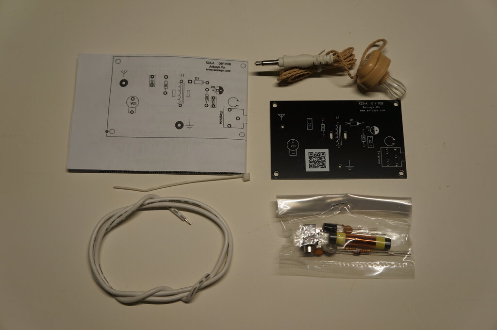
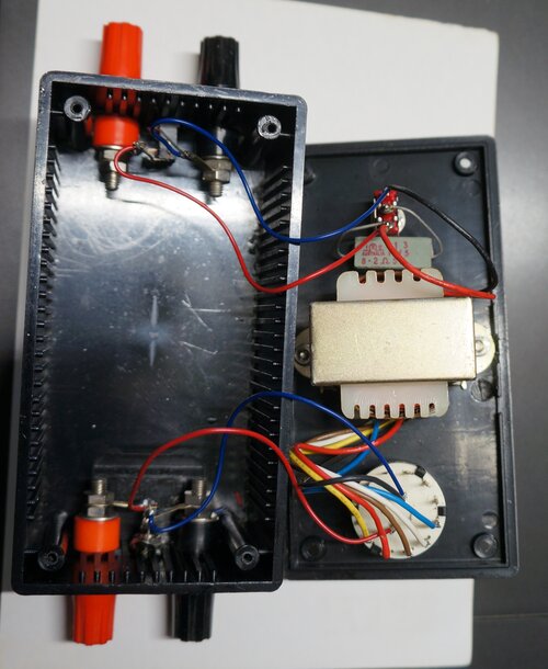
Kit of parts to assemble the Aviosys.
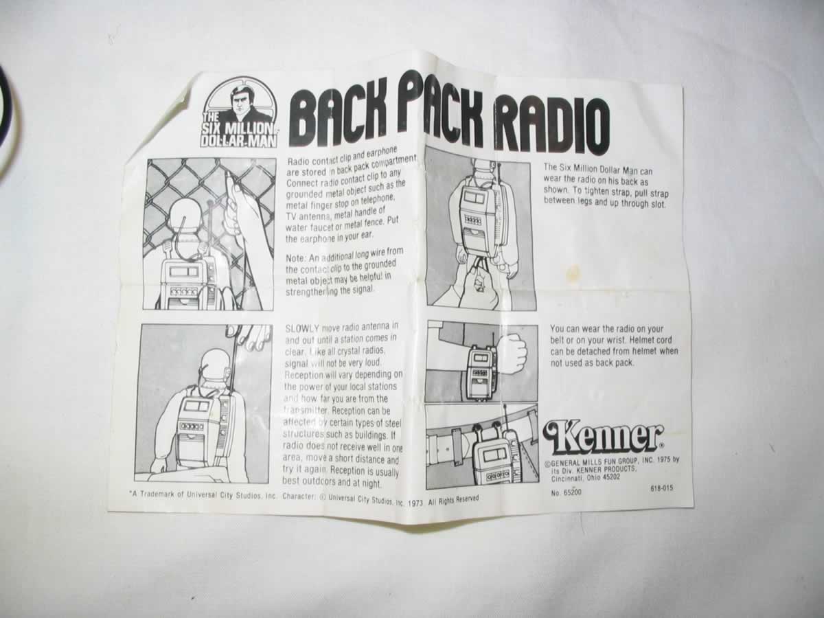
Instructions are bizarre to say the least.
A read through the instructions was not
very promising, and in parts quite erroneous. Aside from the poor English,
I would have to disagree about the design being invented in World War II.
Crystal radios have been around a lot longer than that; in fact at least
as far back as broadcasting began in the early 1920's. True, they weren't
using a semiconductor diode in a glass body, but the catswhisker and galena
detector is nevertheless a solid state semiconductor.
The implication is that the "antenna stick"
(ferrite loopstick) merely needs to be placed "out of a window" to get
signals. One would need to be in an extremely high field strength area,
to receive anything on a crystal set with just the ferrite loopstick. Ironically,
the small size of the one in the kit certainly won't be assisting in that
regard.
The advice to, "never connect to ground,
equal potential and phase will cancel out the signal received." is misleading.
Only after reading this several times did I realise that it means not to
connect the aerial to earth, not to not earth the set in
the normal way - which is how it came across first time reading it.
In fact, no information is given about
earthing the set, which is definitely required in a weak signal area.
The formula for resonance is out of place
where it is; it should have been placed in the section of the instructions
where the tuned circuit is being described.
No description of what "get a outdoor
antenna" is meant to consist of. No details are given for the beginner.
What is meant by, "antenna need to be straighten up"? I presume this implies
the 60cm length of stiff wire provided with the kit is meant to be used
to augment the signal picked up on the ferrite rod. In which case, yes
it would help having it fully straightened out. But no details are provided
about this.
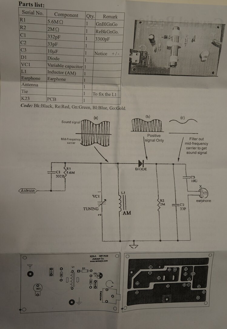
The circuit is equally strange. At face
value, it's a typical crystal set circuit, but looking closer there's a
few odd aspects of design. Why the 3300pF and 5.6M in series with the aerial
connection? These components are only required when the aerial needs to
be isolated, such as with live chassis mains powered sets. Resistors have
been made in preferred values for many years, but R2 at 2M is definitely
not one. The resistor is actually colour coded as 2M, not 2.2M. Strange.
33pF will have minimal effect for RF filtering.
In a crystal set this capacitor doesn't really have any effect anyway,
and as you can see from the Science Fair and Denshi designs, it is not
always included.
The inclusion of a 10uF electrolytic capacitor
is weird. It's not as if there's any significant DC that needs to be isolated
from anything. A couple hundred millivolts with an extremely strong signal
maybe - but that doesn't worry the earphone which appears as a DC open
circuit anyway. There's not even enough voltage to polarise the capacitor.
The diode is a type number I did not recognise, but testing revealed it's
most likely a Schottky type since the Vf was 400mV.
The tuning capacitor is a ceramic trimmer type. I can't see it being able to tune the full broadcast band with such a small capacitance. It isn't really very practical to use as a normal tuning control since it requires a screwdriver to adjust. Plastic variable capacitors with knobs are still being made, so why didn't they use one of those?
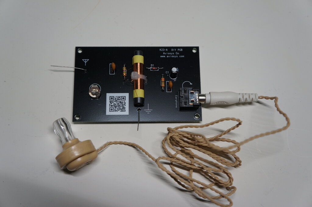
Assembled kit. The length of wire supplied for the aerial is insufficient
for my location so was not used.
![]()
Distances to the Sydney transmitters from my location in the Blue
Mountains.
A further difficulty arises due to the
loading of my aerial. It is a long wire of about 30m length, and appears
as a capacitance of about 1300pF.
When connected to a normal* crystal set,
this capacitance is added to the tuned circuit, and thus restricts the
upper frequency tuning range. (*'normal' being a basic single tuned circuit)
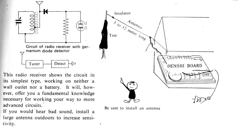
The Denshi Block Set.
Note that the circuit and instructions
don't show an earth connection. In practice, in strong signal areas this
is not necessary with sets using a ferrite rod. In fact, providing an earth
can actually impair the selectivity. These sets seem to work best with
an aerial connection alone, relying on stray capacitance for the earth
'connection'. In my original location 13km from the transmitters, a few
metres of aerial wire, and no earth gave good volume and acceptable selectivity
with this and similar sets.
In my present location in the Blue Mountains, with no earth connection, this set did provide reception of the ABC 50kW transmitters, although not strong enough to be of any entertainment value. With the set earthed, and the aerial connected via a capacitor, the 50kW transmitters came in at good volume. It was also possible to receive some of the commercial 5kW stations; in particular 873kHz and 954kHz. While very weak, the speech and music was quite intelligible. I wouldn't say it was quite entertainment level, but in a perfectly quiet room, the program can be followed.
The Science Fair Set.
As per the Denshi Block set, this also
worked better with no earth connection close to the transmitters. Now that
I live much further away, an earth connection is necessary.
I tested the Science Fair crystal set
to find out how much capacitive aerial loading it could tolerate. Using
the "short" aerial terminal, the maximum loading was about 45pF to allow
tuning from 530 to 1600kHz. The more capacitive loading, the more the upper
limit is reduced.
An obvious thing to do is connect a series
capacitor of about 45pF between the aerial and crystal set, to reduce the
capacitance seen by the tuned circuit. Indeed, this does restore the correct
tuning range, but unfortunately we now have a capacitive voltage divider,
and the signal is severely attenuated.
The only way to hear anything on this
set is to increase the series capacitor to about 420pF. This restricts
the tuning range to just above 700kHz, but does allow the two 50kW ABC
transmitters to be heard at an acceptable volume.
It might be assumed that tapping the aerial down the coil would help. In this case, connecting the aerial directly to the "long" terminal does solve the problem, in that the tuning range is now 520kHz to 2.5MHz. But again, signal strength is reduced, because of the RF being applied to a smaller section of the coil. While the commercial stations can now be tuned, they are so weak as to be unable to understand what is being said. The ABC stations can be listened to, but are weaker than with the "short" terminal connection with series capacitor.
Of the two connections, the most volume from the ABC stations comes from using the "short" connection with 420pF in series. In summary, it is not practical to listen to the commercial stations at my location on this set. The best that can be had is to hear that, "there's something there, but I don't know what they're saying".
The Aviosys Set.
This design has only a single tuned circuit
with no tappings on the coil. Used as intended with its 60cm wire aerial,
placed near the output of a signal generator, it tunes from about 490kHz
to 1100kHz. Perhaps removing some turns on the aerial coil would be worthwhile
to obtain greater coverage of the broadcast band.
Of course, in my location no signals can
be heard with the 60cm aerial. Thus, the outdoor long wire must be used
with a series capacitor. In this case, about 60pF allows tuning in of the
ABC stations. Again, the commercial stations are too weak to be received,
even if the series capacitor is reduced, to allow the required tuning coverage.
Unfortunately, the crystal earphone supplied
with this kit has an intermittent open circuit. Testing was continued using
headphones with a matching transformer. A further fault is in the design.
The 2M load resistor is too high resulting in a weak distorted sound. This
clears up when the resistor is reduced to around 100k. Best performance
is with headphones, and the matching transformer connected directly as
the diode load. In this regard, it is almost as good as the Science Fair
set in terms of volume.
The Home made Set.
Testing was done with headphones and matching
transformer, since it was designed and built back in the days of high impedance
magnetic headphones. Again, only the two 50kW ABC stations were practical
to listen to, although with a capacitor in series with the aerial, the
5kW commercial station on 954kHz could be 'heard'. It was certainly not
audible enough to be of entertainment value, but one could hear it was
music and identify the tune. Best reception for the 50kW stations was with
the aerial connected straight to the lowest tapping.
How do they Compare?
The Denshi Block set easily outperformed
the others. Most of this comes down to its high earphone sensitivity. The
quality Japanese parts also help. When headphones were used instead, its
performance dropped to that of the next best performer, the home made set.
In summary, all four sets were restricted
to receiving the two 50kW ABC transmitters for entertainment strength sound
level. The Denshi Block could also receive two 5kW stations with usable,
though weak, reception. While the home made set could receive a 5kW station,
it was not of any practical use.
With the exception of the Denshi Block set and its crystal earphone, the other three sets provided about the same volume as each other.
In order from best to worst, the sets were; 1) Denshi Block, 2) Home made set, 3) Science Fair, 4) Aviosys.
I did briefly experiment with tuning the
aerial using a pi matching circuit, but without any improvement.
There have been elaborate crystal set
designs in the past with supposed DX qualities. Whether or not one would
give better reception of the 5kW transmitters, I don't know. One thing
is definite, and that is a certain minimum signal must be received, to
drive the headphones or earphone to an audible level. If that signal is
not there, no amount of passive circuitry will being forth results.
So what kind of signal level do we
need?
Using the best case scenario; i.e. the
Denshi Block, the signal generator was connected via a capacitor of 83pF,
and set to 900kHz with 50% modulation. The weakest detectable signal was
400uV. That is, you could hear something was there, but not what it was.
For the signal to be identifiable, it
needed to be up around 1mV. For satisfactory entertainment value, 1.5mV
and above is required.
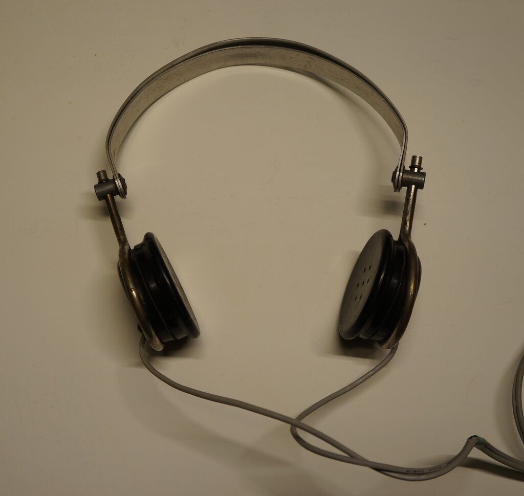
Brown type F are typical of high impedance headphones. These were
bought from a disposals store in 1979 for $2.00.
However, one must not get lost in rose
coloured nostalgia. By and large, old fashioned high impedance headphones
are awful things in terms of sound quality and comfort. With their thin
steel diaphragms, they have a limited and peaky frequency response, with
high distortion.
The hard bakelite earpieces are very uncomfortable
against the ears. Not even I, lost in the days of vintage technology, like
to use them.
The answer is to use modern headphones.
Far more comfortable, and acoustically efficient, these are capable of
true hi-fi sound. The only catch is they're low impedance - which doesn't
suit crystal sets and other simple receivers. This is simply overcome using
a matching transformer, to step up the typically 8 to 32R impedance to
20k or more.
Along with the two crystal sets were supplied
a variety of headphones, and these were to be tested to see which was the
most sensitive, and also to find what the best impedance was. Since it
was the most convenient for testing, and that it was one of the better
receivers, the home made crystal set was used.
1. Tech.inc "Verve".
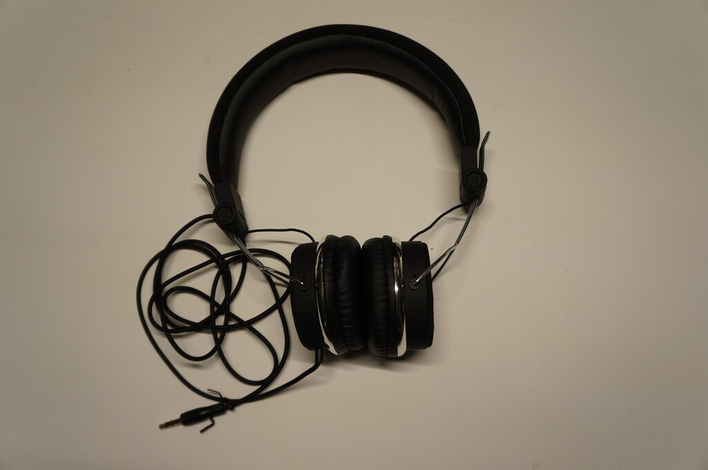
Sold by the Warehouse.
2.Tech.inc "Shockwave".
Also sold by the Warehouse.
Impedance 64 ohms.
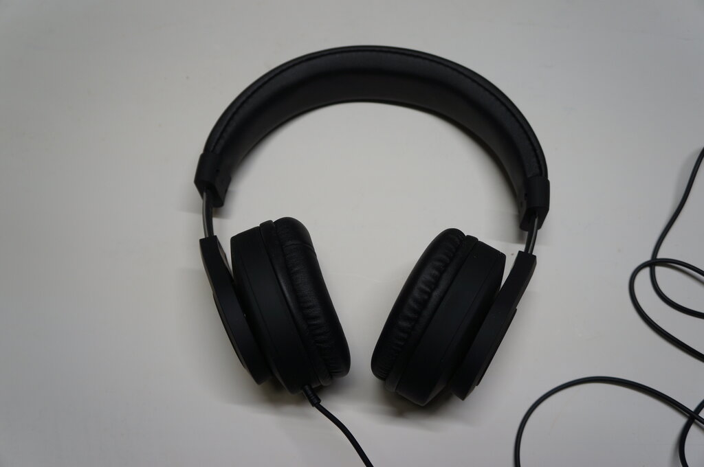
3. Sennheiser HD 400S.
Microphone. Remote control.
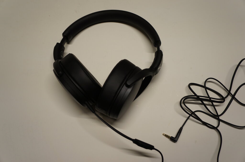
4. Digitech AA-2133
Sold by Jaycar.
Impedance 32 ohms. Microphone. Remote control.
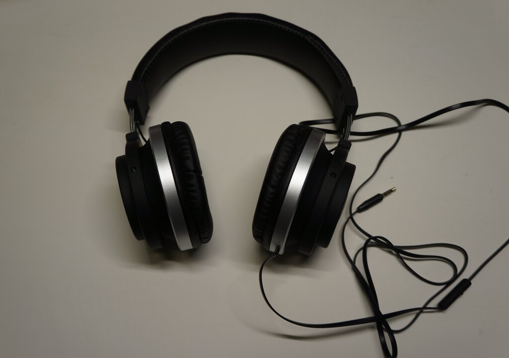
5. Marley Liberate XL
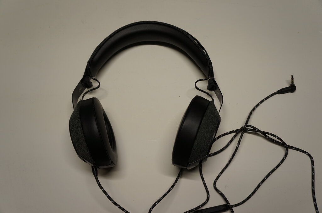
Once sold by houseofmarley.com.
Fabric carrying case. Fabric covered cord. Microphone. Remote control.
6. Marley Positive Vibration.
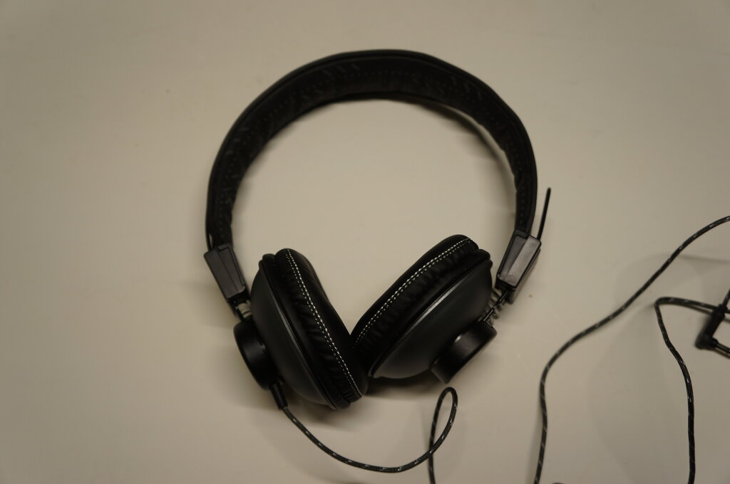
Also once sold by houseofmarley.com.
Fabric covered cord.
Measuring the impedance was done on the
basis of the voltage across the headphones being half the source voltage,
when a resistance was connected in series. This resistance is thus equal
to the impedance.
In practice, the signal generator has
a certain output impedance and this has to be taken into account. As the
series resistor is adjusted, the load seen by the signal generator changes,
which also changes its output voltage.
Each time the series resistor is adjusted,
the signal generator output also has to be adjusted to compensate. To simplify
the procedure, the signal generator impedance needs to be made very low,
relative to the load under test.
A simple way to do this is with a step
down transformer. The test set up is shown below:
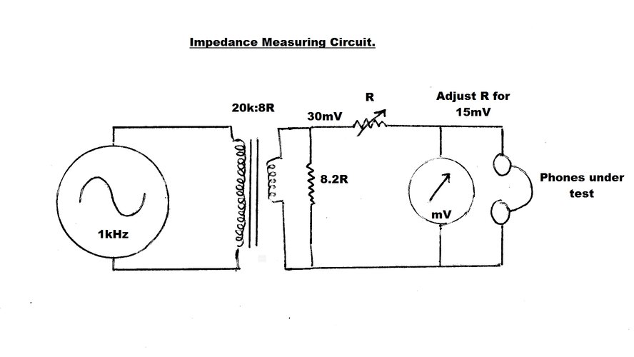
By means of the transformer and 8.2R load
resistor, the source impedance is only a few ohms. Since the headphone
impedance is many times this, the source voltage remains reasonably constant
as R is adjusted.
A convenient source voltage is 30mV at
a frequency of 1kHz. It follows that when the series resistor, R, is adjusted
so the phones receive 15mV, R is equal to the headphone impedance.
As will be noted, the specified impedance
of the headphones, where listed, was not the same as that measured. One
variable which will affect the measurement is the frequency, and it is
not known what the manufacturer used.
1kHz is typical for audio testing and
is what I chose. Note also that the impedance was measured for one driver,
so when the drivers are in parallel for mono listening, the impedance is
halved.
| Impedance per channel (1kHz) | Sensitivity (1 = max) | Sound Quality (1 = best) | |
| Marley Liberate XL | 55R | 1 | 2 |
| Marley Positive Vibration | 70R | 2 | 3 |
| Warehouse Verve | 110R | 5 | 4 |
| Warehouse Shockwave | 150R | 6 | 5 |
| Sennheiser HD 400S | 90R | 3 | 1 |
| Digitech | 110R | 4 | 6 |
Laboratory testing equipment does actually
exist for the sensitivity test, consisting of a dummy head with calibrated
microphones placed in the ears. Since I have nothing of the sort, the test
was done subjectively. The difference between highest and lowest was quite
marked, and without any doubt, the Marley Liberate XL was the most sensitive
and best suited for crystal set use.
Again, the sound quality test was also
subjective. For this test, a TDA7000 FM receiver was used. It is no surprise
that the Sennheisers were the best in this regard. Next best were the Marleys.
It is common in the present day to include a microphone with headphones, for use with mobile phones. This makes use of a fourth conductor on the 3.5mm plug. When the phones are plugged into a normal 3.5mm stereo socket, this fourth connection is ignored, and the phones function normally.
Test Matching Transformer.
In order to use these low impedance phones
with a crystal set, a matching transformer is required. Some time ago I
built a universal test transformer with an 8R secondary for driving a speaker
or low impedance phones, and with a primary selectable from 2k to 30k.
This makes it a simple procedure to determine
the best load impedance for a circuit - simply switching between the transformer
primary tappings until the loudest signal is obtained.
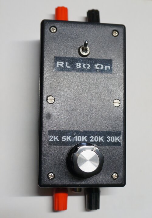
Test matching transformer has multiple primary impedances.
![]()
Circuit of test transformer.
The test transformer is based around a
multi-tapped 5W audio line transformer, of the type used for 100V line
PA systems. The primary impedances are not quoted on the transformer, since
they are not actually relevant for PA system use. Instead, the appropriate
tapping is selected for the required power into the speaker. However, the
impedances can be calculated. More on PA line transformers is here.
In the test unit, the tappings are selected
with a five way rotary switch. Two binding posts and an RCA socket connect
the input.
The secondary impedance is the usual 8R.
This connects to another set of binding posts for connecting to a test
speaker, and/or a CRO, audio voltmeter, etc. A stereo 3.5mm socket allows
for convenient connection of headphones.
Also included is an 8.2R 5W resistor which
can be switched in as a load for power output tests.
It's a very useful piece of test gear
which gets a lot of use. While the primary impedances do suit valve circuitry,
it must be mentioned that PA line transformers do not have an air gap in
the core. This means they are officially unsuitable as single ended output
transformers where plate current flows through the winding.
The problem is when DC is passed through
the windings, the core is magnetised which reduces inductance and can cause
saturation. The result is a lower output available before distortion sets
in.
However, in practice, they can be used
as output transformers, provided the current is kept low relative to the
core size. Certainly, for the purposes of testing where a go/no-go test
is more important than hi-fi quality, this is not a problem.
What Impedance for a Crystal Set?
It was found that with all the crystal
sets tested that the headphone impedance was not particularly critical.
Anything from 2k to 30k worked satisfactorily, but if one had to choose
an optimum impedance, 20k did provide the highest output.
Note that because the headphones have
a greater impedance than 8R, this is reflected in the primary impedance.
Taking the Marley Liberate XL phones as an example, with both drivers in
parallel, the impedance is about 27.5R.
The primary impedance of the transformer
increases by 27.5 / 8, which is 3.4 times. So, the 20k tap actually appears
as 68k. In practice it won't be that high because the transformer isn't
actually designed to be used that way, due to the turns per volt
ratio being optimised for an 8R load.
Crystal Set as a Tuner.
It could be imagined that the higher the
load impedance is, the higher the audio output voltage. To a large extent
this is true, and with a crystal set fed into a high impedance audio amplifier,
weaker stations now become audible. So why not simply make headphones of
an extremely high impedance? With only a certain voltage available from
the crystal set; for example 500mV, the higher the headphone impedance
is means that less current flows through the driver coils to actuate the
diaphragms. The best headphone impedance is really a compromise between
the amount of driver current that can be obtained, and how much the audio
voltage is loaded down.
When a crystal set is fed into a high
impedance amplifier, these restrictions don't apply, and reception is substantially
improved. In view of the broad selectivity, a crystal set also makes a
very good hi-fi AM tuner.
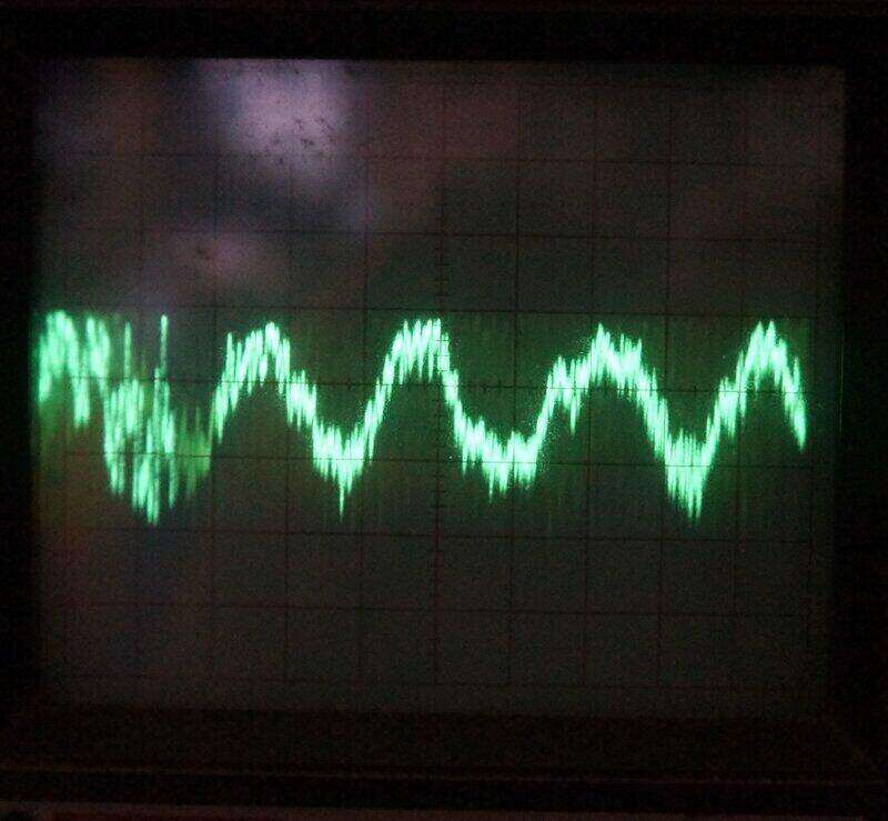
Tuned to the 50kW station on 702kHz, about 300mVp-p was present
across a 1M load.
The home made crystal set seemed to work best with a load resistance of about 1M. Tuned to the strongest station in my area, it could produce about 300mVp-p (106mVrms). This is quite adequate to drive a sensitive valve amplifier.