Gloss paint shows up badly in the photo. It does look better than this!
Gloss paint shows up badly in the photo. It does look better than
this!
This has undoubtedly been my longest running project. Starting in at the end of 1993, it is now March 2022, and I have finally completed the receiver to the point where it now provides 30 line pictures.
Background to Mechanical TV.
Prior to the development of cathode ray
tubes, television used mechanical methods to scan and display the images.
Most common of these was the Nipkow disc. Rotating drums, mirror screws,
and vibrating mirrors were other methods used to achieve the same result.
As the image is scanned, its light output was fed into a phototube - a
device which had already been developed for use with the sound track of
movie film. This produced a video signal which could be transmitted in
the usual way.
At the receiving end, the signal modulated
a light source which was scanned in the same manner as the transmitter.
The light source has to be quick acting, which rules out incandescent lamps.
Most popular were neon tubes - resulting in an orange picture. Effectively,
the receiver is just the reverse of the transmitter. Since the light source
brightness was dependent on the phototube illumination at any one point
of the picture, it follows that provided the two scanners are in step with
each other, a picture will be built up.
This was one of the challenges of early
TV - how to synchronise the scanners. Many methods were tried. Baird's
system used a form of sync pulse at start of each line, similar to modern
electronic TV. On the same shaft as the disc motor in the receiver was
a 'phonic wheel', or Baird's derivative, the 'cogged wheel'; roughly similar
to a synchronous motor, which responded to the sync pulses. In the U.S.,
with widely reticulated AC mains, synchronous motors were popular. One
limitation with this scheme is that it was not possible to synchronise
the set if it was used in an area with a different mains supply. A method
to overcome this was a separate transmitter purely for sync pulses, which
drove a synchronous motor in the receiver. Many experimenters did not bother
with synchronising control circuits as such, but rather used a hand held
rheostat to manually keep the motor in sync.
The methods of mechanical TV have been
well documented, with construction plans available in period literature.
Commercially made sets were available,
occasionally including a radio receiver for the video signals, but mostly
they were just a stand alone 'monitor', to use the modern term, which was
fed from an existing receiver. Television broadcasts were made experimentally
from the late 1920's, onwards, in the U.K., U.S, and Europe. Unfortunately,
Australia missed out on these pioneering times with very little interest
in television here. A few amateur radio operators performed experiments
for a short time, but there were never any regular transmissions.
The Baird System.
30 lines at a frame rate of 12.5 pictures
per second was chosen by Baird, since the highest video frequency (about
10kHz) just fitted into a MW broadcast channel. Similarly, the vertically
scanned 7:3 aspect ratio made the best use 'portrait' images. Existing
BBC transmitters were used by Baird, and by 1932, the BBC had taken over
the program production themselves.
Sound and vision was at first transmitted
alternately, and then from March 1930 simultaneously with two transmitters.
Broadcasts of the Baird system ran until September 1935, by which time
the high definition system was well into its planning stage.
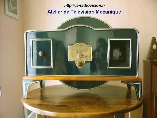
The most well known mechanical TV receiver
(really just a monitor), is the Baird Televisor. About 1000 of these were
made by Plessey for Baird Television Ltd. between 1929 and 1932.
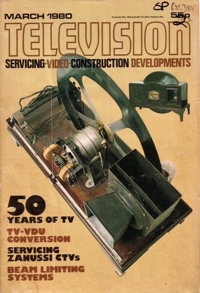
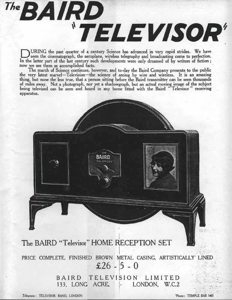
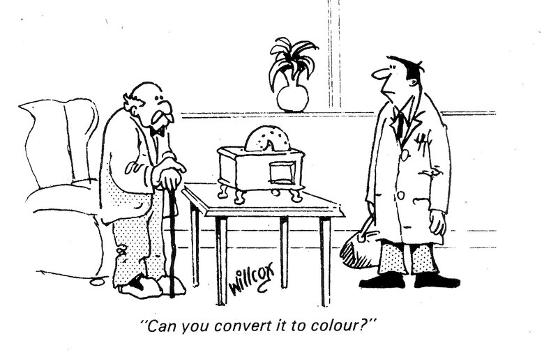
The Baird Televisor is shown on the March 1980 issue of Television,
and as advertised (with a rather exaggerated picture size!)
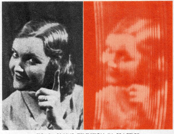
This gives an idea of the picture quality from the Televisor.
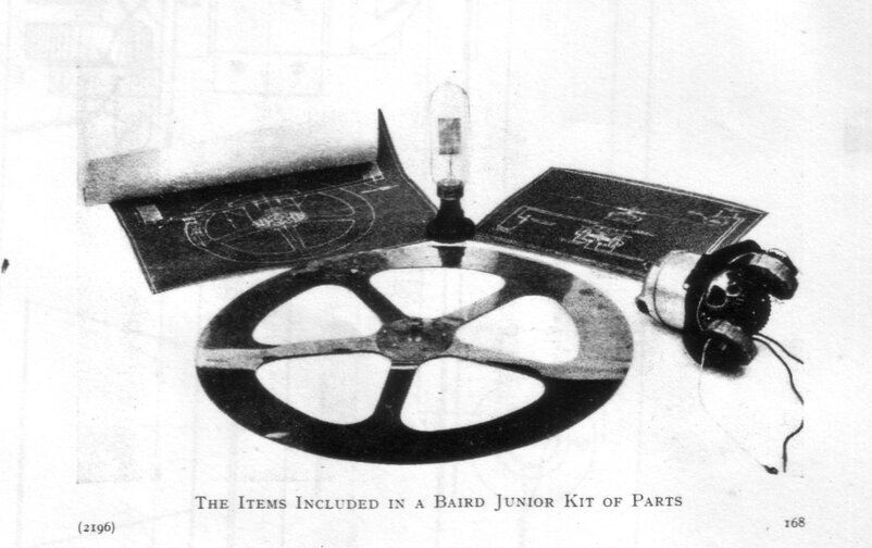
Baird Junior Kit of Parts - for those who want to build their own
at lower cost.
Some sources claim that about 50 Plessey
Televisors still exist. They are all in the hands of museums or collectors.
Two exist in Australia that I know of; one at the Power House Museum, and
one at the National Film And Sound Archive (the latter I have seen in person).
Unfortunately, when they do seldom come
up for sale, they are horrendously expensive. I suspect that with the advent
of electronic standard converters appearing in the first decade of the
2000's, this has increased their value even more, since one can now provide
them with a signal from any modern video source.
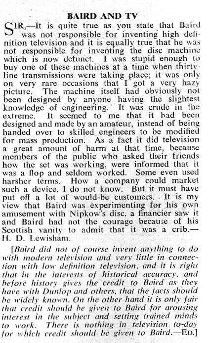
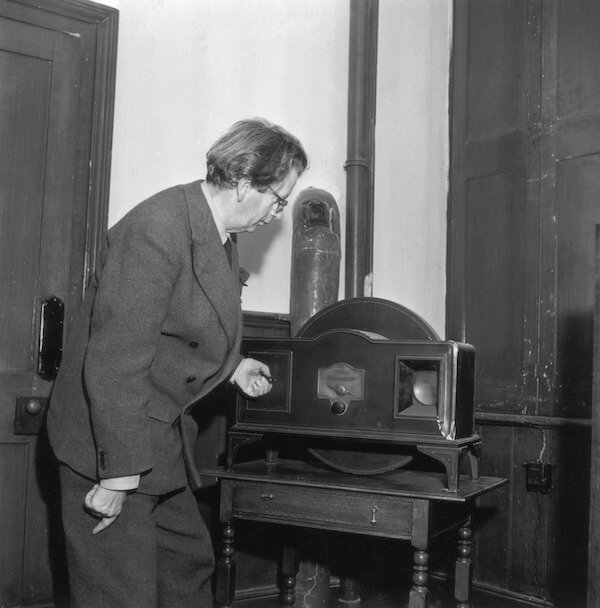
From Practical Television, August 1957. H.D. was evidently not happy
with the performance. At right is Baird with his beloved Plessey Televisor.
There is virtually nothing in the way of photos from the time showing what the picture quality was like. What does exist appears to be closed circuit images and not off air. It can be imagined the type of receiving set used at the time, with interstage audio transformers, and grid leak or anode bend detectors, would introduce distortion and have a poor frequency response. One could surmise that the system was introduced ahead of the technology that could have got the best out of it. In the modern day with a good quality video signal and proper sync circuitry, the results can be very good indeed.
How did I get into this?
In the Xmas holidays of 1979, I saw an
article in the "New
Scientist" for the 4th November 1976, which described recreating a
Baird broadcast. To create the signal, a commercially made Televisor was
used in reverse, with a phototube in place of the neon lamp.
The whole concept fascinated me of the
Nipkow disc, and how simple it was. For the fun of it, I put holes in a
paper plate and stuck it to the shaft of a fan motor to watch it scan.
Then, a few months later, I found a book in the school library called "Television
Magic". It showed a Baird Televisor, and its typical 30 line image. I had
totally unworkable thoughts of a 100W incandescent light bulb behind a
disc, being modulated with an FM radio receiving off air TV, but I was
only 12!
Around 1982, some very cheap 240V open
frame brush motors had been advertised from Sheridan Electronics. I thought
they would suit a mechanical TV. And so to my next experiment. This time
I used plywood discs with holes suitably drilled. The light source was
an NE-2 neon bulb, fed from the output of a tape recorder via a 6 to 240V
transformer used in reverse. The pickup device was an ORP12 light dependent
resistor fed into the microphone input. Light dimmers controlled motor
speed.
Unfortunately, nothing came of it all.
In retrospect it's easy to see why. Firstly, the neon had no bias which
would have caused excessive distortion. Secondly, the ORP12, being a cadmium
sulphide device, is way too slow to respond to the video frequency, and
furthermore, it can't output a signal unless it's provided with a current.
I also tried a 10" gramophone record as
a scanning disc. This was a lot better than the plywood job.
I finally did get results of a kind when
I substituted the LDR with a silicon solar cell. However, it was merely
a shadow that moved. In retrospect, the neon should have at least been
biassed to produce a mean level of light, rather than using the video pulses
to provide the entire excitation.
Electronic TV then became my preoccupation
with the successful construction of the RTV&H
5" and 21" sets, commencing at the end of 1983
Around 1985, much researching was done,
finding old books in the NSW State Library about mechanical TV, and in
particular, the Baird format. Ideas were had of broadcasting to a friend
in a suburb some distance away. We'd use CB radios as the radio link. Of
course, looking back at this now, it wouldn't have worked very well at
all, for such transceivers are only intended for voice communication; about
300 to 2500Hz.. I then had ideas of a purpose built transmitter with an
807 valve, as described in a 1946 issue of Radio & Hobbies.
That was it for a while, as other projects
distracted me away from mechanical TV for the next 10 years.
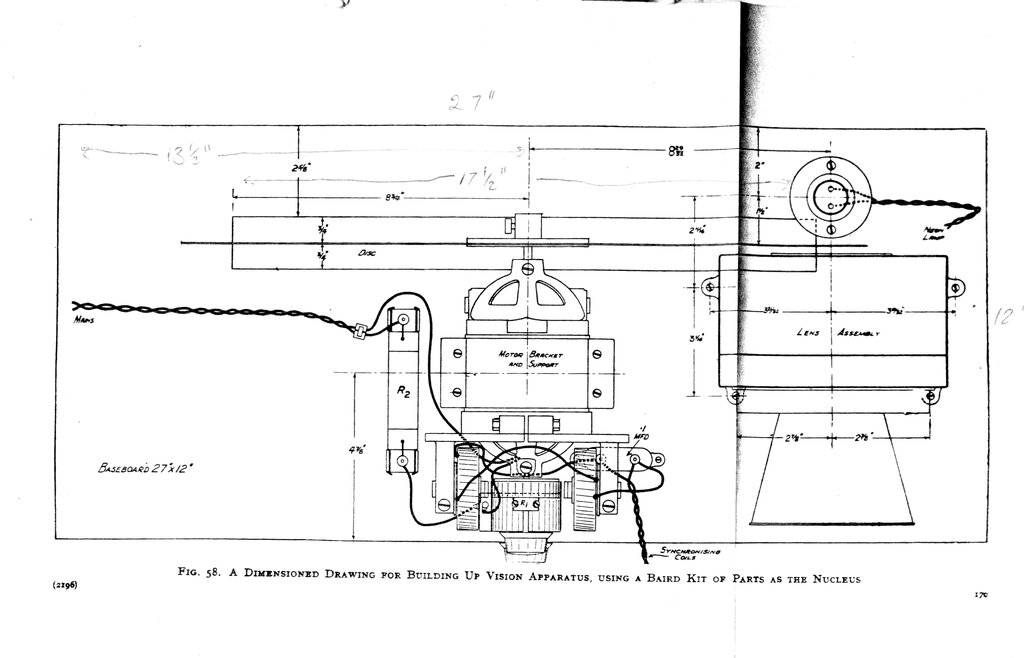
From "Television for the Amateur Constructor", this gave the necessary
dimensions for the baseboard and parts layout.
Televisor disc motor is from a DEC LA-120 printer.
Nothing more was done with the mechanical
construction for the transmitter, and it remains that way until the optics
and electronics have been developed.
Remember, this was well before the internet
was what it is today. The only information was from old books in libraries
and a few vague magazine articles.
March 2022, the Televisor is operational.
The Receiver.
Since proper "television" neon lamps are
obviously no longer made, and very expensive when original examples do
come up for sale, another light source was required. This was 1993 remember,
and the high brightness white LED's we take for granted now just weren't
available. A panel with lots of NE-2 neon bulbs was one option. I'd had
no luck with finding any "Osglim" type neon bulbs (except for one with
a broken off electrode), since one of these would be the next best thing.
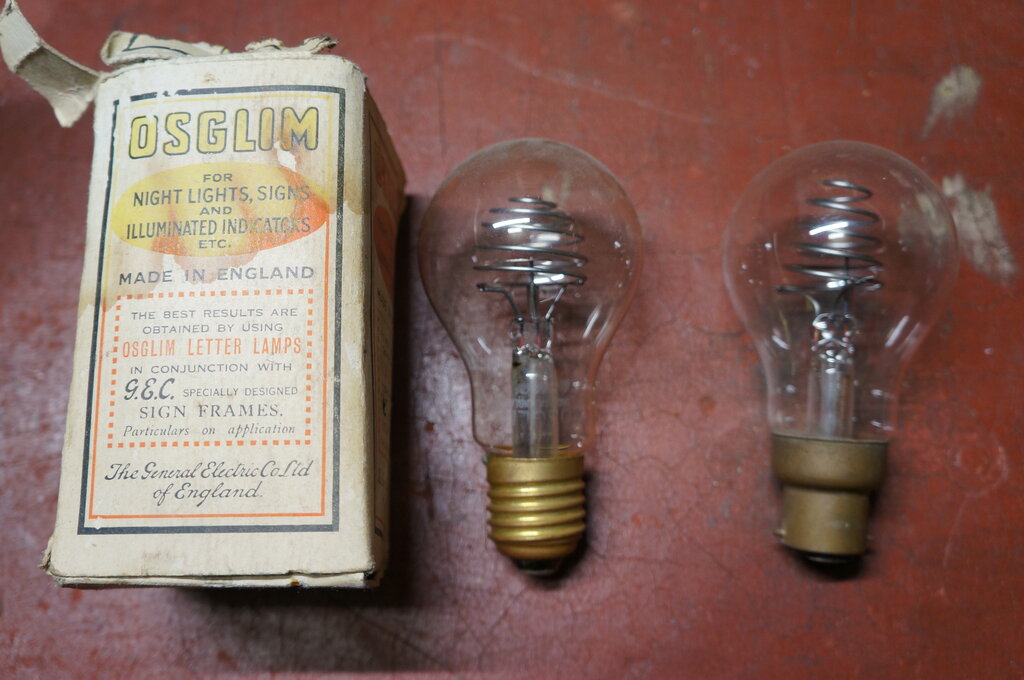
Back in the day, the "Osglim" neon bulb was a poor man's substitute
for the flat plate television lamp. These examples came to me years after
I started my Televisor, otherwise I would have used one.
Another option would be to make a panel
using ordinary orange LED's, since at least the colour would be similar
to the original neon bulb.
Then I hit up on the bright idea of a
fluorescent tube (pun intended!). Being a gas discharge lamp, like a neon,
it would respond fast enough to the video signal. It would have excellent
brightness, and best of all provide a nice white light. I chose a 4W tube
as being just the right size. Experiments showed that it could be modulated
with an ordinary audio type power valve.
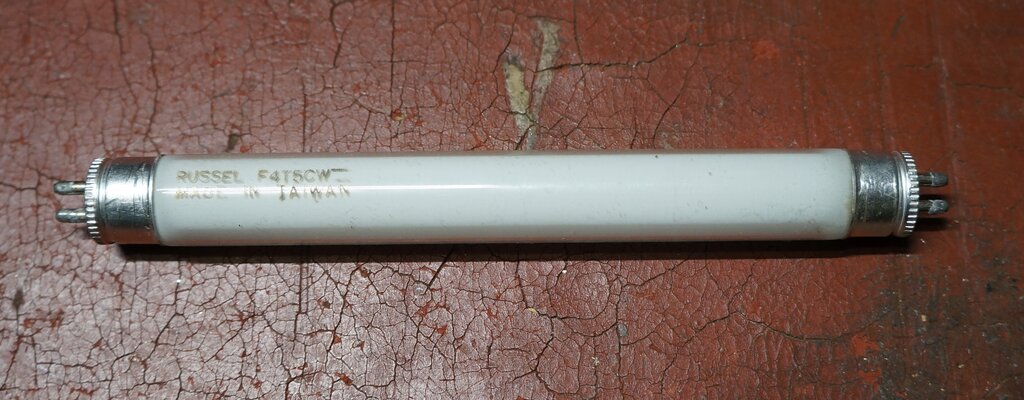
4W fluorescent tube seemed like a good idea since it was bright,
the right colour, and easy to modulate. Unfortunately, phosphor persistence
was a problem.
A light box was made up to mount the fluorescent
tube behind the disc. A piece of velum (from my PCB making activities)
diffused the light ,so that the rear of the disc was evenly lit.
Next, a 'viewing tunnel' was constructed
to mount a lens in front of the disc, and to provide some shield against
ambient light. A half convex lens which came from a dismantled overhead
projector, seemed to have about the right focal length and diameter, so
was put into service.
With the motor, disc, light source and
lens all mounted, the electrical experiments could commence to develop
a suitable circuit.
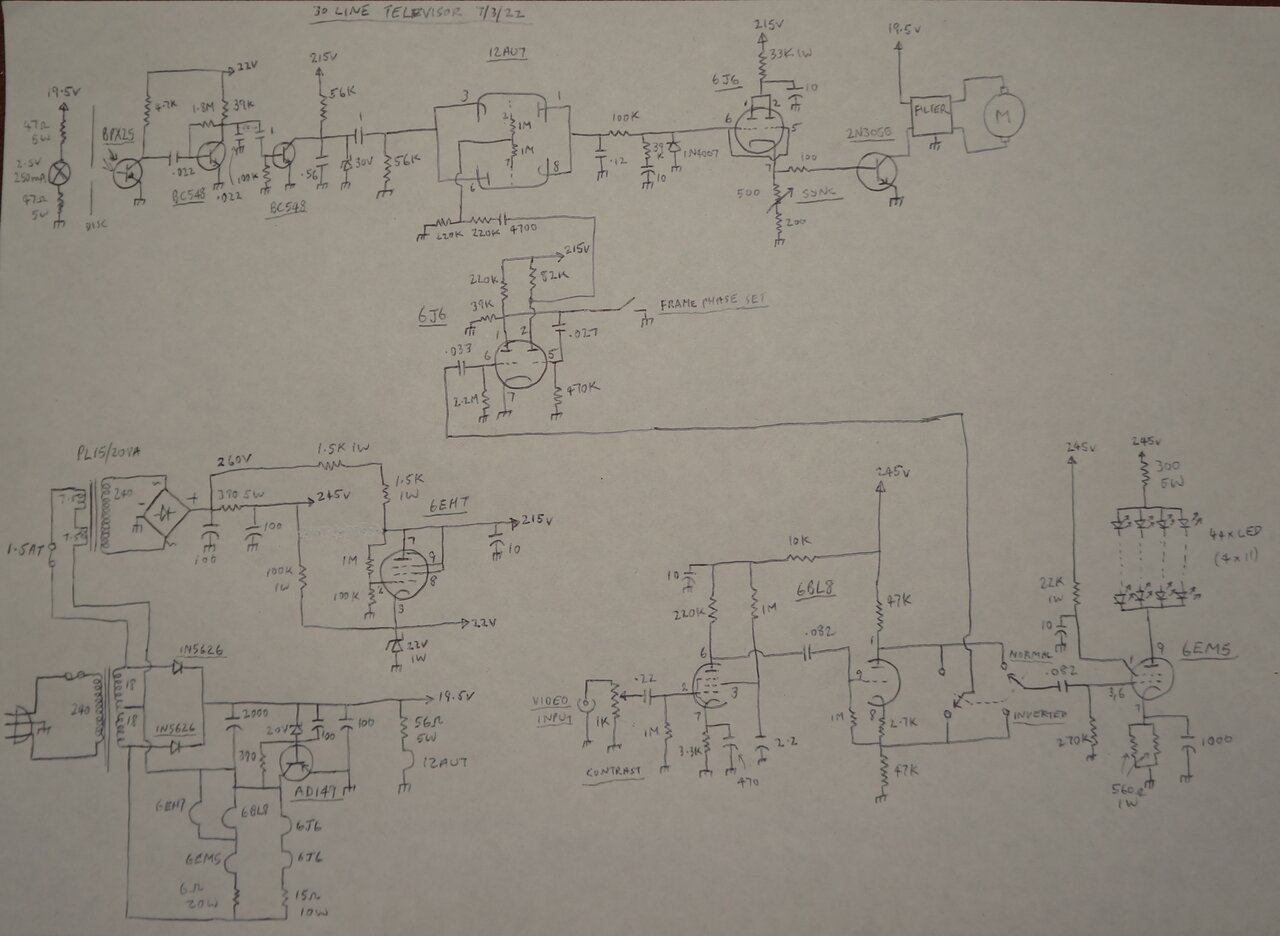
The eventual outcome was this:
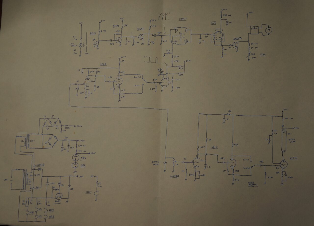
The 1993 circuit.
Vision Amplifier.
I decided on a vision input signal typical
of audio equipment; i.e. up to about 1Vrms. This was in view of signals
being recorded on ordinary domestic tape recorders, for example.
The amplifier follows conventional practice.
A 6BL8/ECF80 pentode provides a voltage gain of 230. Depending on the signal
source phasing, the video signal could be positive going with negative
going sync, or vice versa.
In the Baird days, the viewer would be
instructed to reverse the connections to the receiver output transformer,
or to introduce an extra audio stage, if the picture was negative. To make
things more convenient with the kinds of signal sources used today, I included
the 6BL8 triode as a phase splitter to reverse the phase if necessary.
It is a typical circuit usually used to drive a push pull audio output
stage. Since the cathode and plate resistors are the same, voltage gain
is slightly less than one.
From here, the correctly phased signal
feeds the grid of the 6EM5, a beam tetrode intended for frame output stages
in TV receivers. It is also sometimes used as an audio output valve. I
chose this valve mainly because its plate current rating would suit the
4W fluorescent tube plate load. Since the 300V supply is not enough to
get the tube to ionise, a high impedance 700V supply is 'stacked' onto
the 300V supply, by means of an isolating diode. Once the tube ionises,
the diode conducts, and the 700V supply now comes down to the normal 300V
B+.
Note that the cathode bypass capacitors
are of much higher value than normal. This is to improve the low frequency
response, which has to be as low as 12.5Hz.
To allow for a wide range of input voltage,
and to provide some control over the lamp modulation, a 1k pot acts as
an attenuator, or "contrast" control .
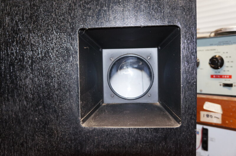
Picture is viewed through the lens.
Sync Amplifier and Separator.
To prevent the contrast control affecting
sync amplitude, a separate amplifier is fed directly from the input.
This amplifier is almost identical to
that of the vision amplifier, based around another 6BL8. Since the lower
frequency response only has to be 375Hz, the capacitors do not have to
be of the high values previously required.
Again, phase switching is required to
ensure correct sync polarity, but note that it is the opposite to that
in the vision amplifier. This is because of the phase reversal in the following
sync separator.
The sync separator is based around a 6J6 twin triode. The composite video signal feeds the grid at pin 6. Since this triode operates with no initial bias, and the plate voltage is restricted by the 39k resistor, the signal is heavily distorted, so that the luminance portion of the signal is chopped off, leaving only the sync pulses. By passing these pulses through another stage, also operating with no bias, the clipping is even more effective. The result is 150Vp-p sync pulses at pin 2.
Sync output from the 6J6.
I had decided to copy electronic TV with regards to sync pulse amplitude vs. the luminance signal. That is, sync pulses would be 30% amplitude, with the luminance being the remaining 70%. Thus, the sync pulses are blacker than black in the normal way. The original Baird signal uses the black level only for sync pulses, which has the disadvantage of sync stability being affected by scene content.
Disc Reference Pulses.
Since a DC motor is being used, this precludes
using the sync pulses to directly drive a synchronous AC motor. Instead,
a phase locked loop is used. Aside from sync pulses, the PLL also requires
locally generated reference pulses. That is, a pulse at the start of every
line as the disc rotates. If the disc pulses should be running fast with
respect to the sync pulses, the correction voltage drops the speed of the
motor. Conversely, if the disc pulses are running slower than the sync
pulses, the motor speeds up. In this way, the correction voltage keeps
the motor in sync with the disc pulses. In the modern day, the same principles
are used to lock the head drum motor in a VCR to the frame sync pulses.
30 holes are drilled around the disc near
the centre. These holes are in line with the normal scanning holes. Since
they are used to generate a pulse only, and not for scanning, they
are arranged in a circle. A beam of light shines through the holes and
onto a BPX25 photo transistor. As each hole allows the light through, the
photo transistor conducts, creating a pulse at line frequency; i.e. 375Hz
for a 30 line picture at 12.5 frames per second.
The lamp is a 2.5V 250mA prefocus type,
as used in the "Penlight" type of torch. It runs from the 20V supply through
two 47R 5W resistors. DC is used to power the lamp so that there is no
100Hz modulation. Normally, such a bulb has a life of typically 100 hours,
but under running it extends that considerably.
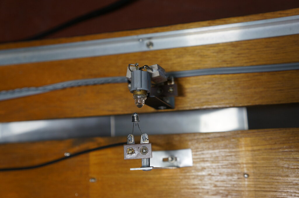
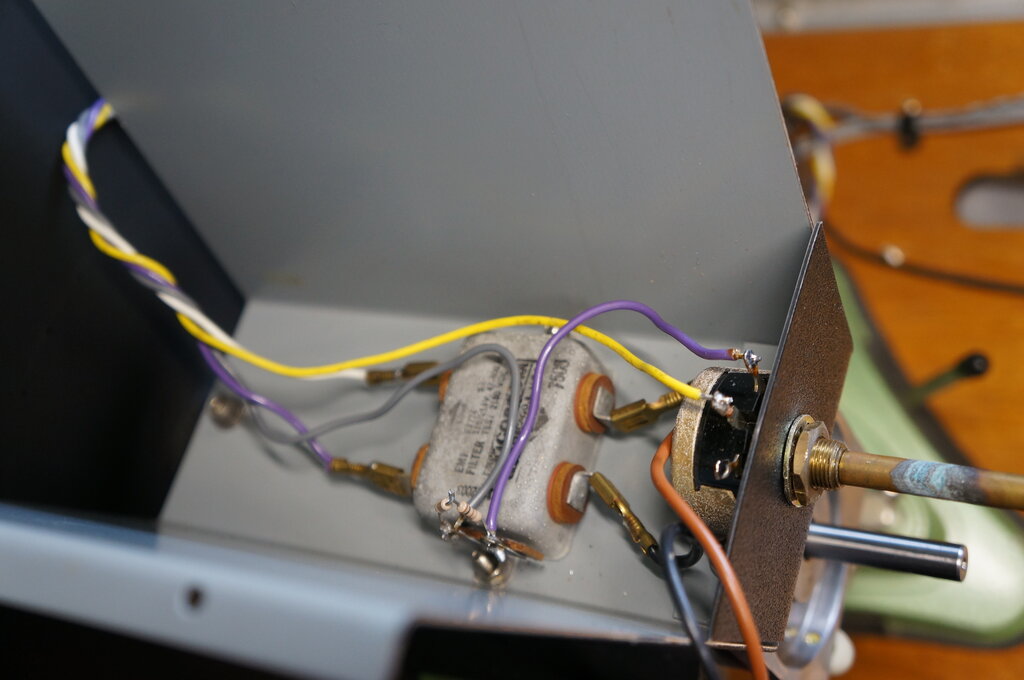
Lamp shines through sync holes in disc to the phototransistor. Slot
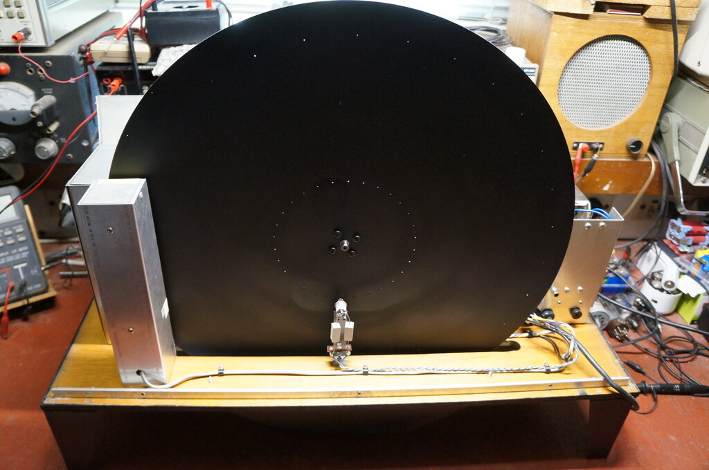
in phototransistor mount provides phasing adjustment.
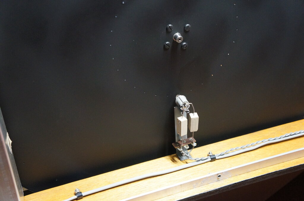
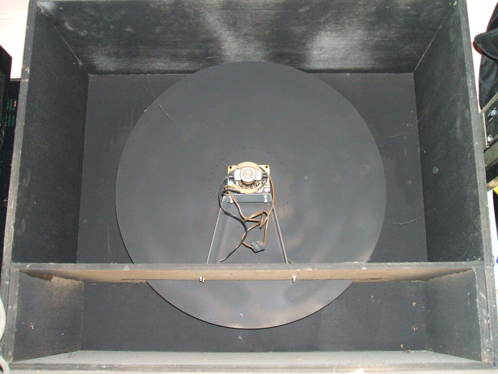
Disc in position. Lamp pointed at sync holes.
The pulses are amplified by a BC548 transistor, the output of which feeds another BC548, acting as a pulse to sawtooth converter. When this transistor conducts, the .56uF capacitor is shorted out and the collector voltage drops immediately to zero. As soon as the transistor stops conducting, the collector voltage rises at a rate determined by the 3.3k and .56uF. With a continuous train of pulses at the transistor base, the collector produces a sawtooth waveform.
Phase Detector.
This is based on a circuit used by CBS
for their colour wheel converter around 1951. By this time, phonic wheels
were out, and phase locked loops were in. After all, they had been used
for line oscillators in electronic TV receivers for a while. The CBS circuit
compared the frame sync pulses with a locally generated reference signal.
This came from a small alternator connected to the colour wheel.which produced
a sine wave. By means of a phase detector, a DC control voltage was produced,
which then controlled the motor speed, via a saturable reactor.
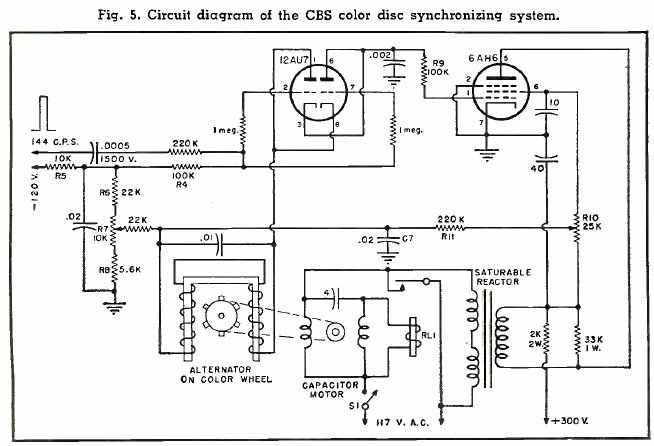
CBS colour wheel synchronises to 144c/s frame sync. R7 sets phasing,
and R10 is the anti-hunt control.
The circuit is from Radio & Television
News for October 1951. The article with brief description can be viewed
at worldradiohistory.com.
A twin triode, 12AU7, detects the phase
difference. The triodes are wired back to back in parallel.
Each triode functions as a gated diode,
and it can be seen that if the left triode conducts more than the lower
triode, the output voltage at its plate will be positive. Conversely, if
the right triode conducts more, the output voltage will be negative.
The triodes are gated by the sync pulses
fed into their grids via the 1M resistors. Since the input to the triodes
at pins 1 and 8 are fed with a sawtooth voltage, we can see that an output
voltage at pins 3 and 6 will be generated when the grids are gated on.
As to what the output voltage is, that depends on how far up the sawtooth
the voltage is when the grids conduct.
In other words, the voltage will depend
on how close or how far the sync pulses and reference pulses are to each
other.
The above circuit was adapted to the Televisor,
mainly by controlling the motor by a power transistor instead of a saturable
reactor. Also, a sawtooth is used instead of a sine wave for the reference
signal.
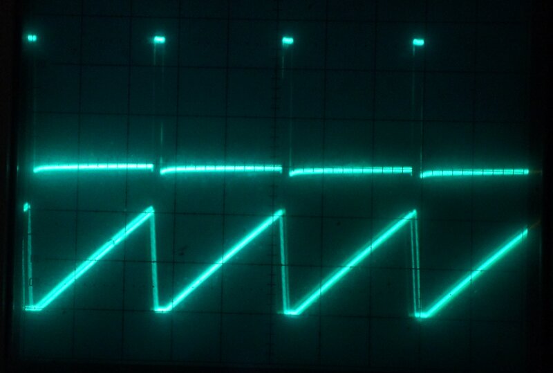
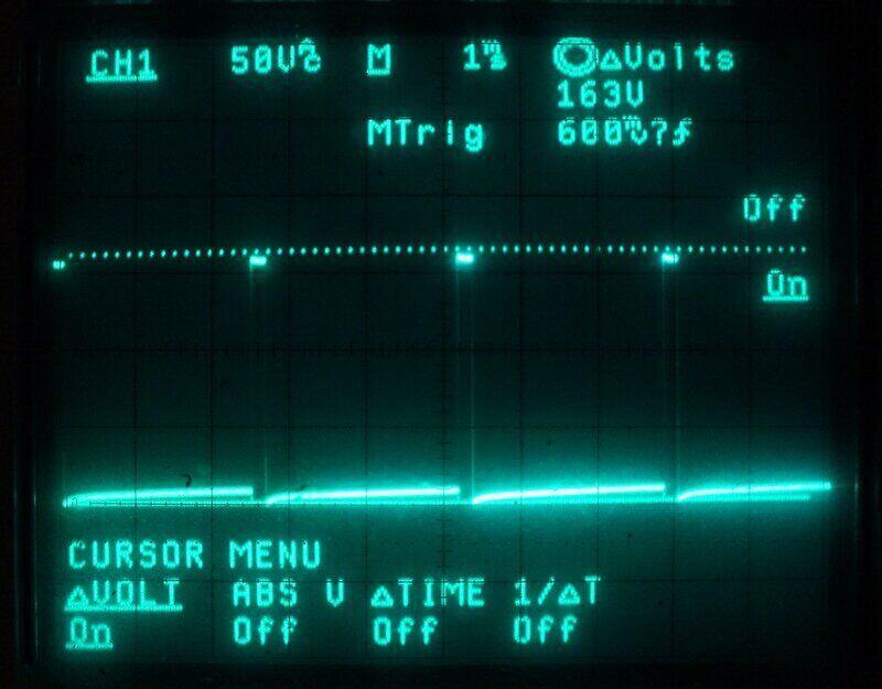
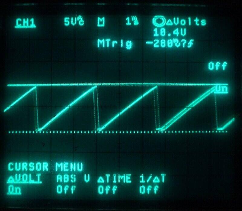
Phasing between sync pulses (top) and disc (bottom). Photo was taken
after the sawtooth generator was improved.
Motor Control.
Returning now to the Televisor circuit,
the correction voltage from the phase detector is filtered by a .12uF capacitor
to remove most of the 375Hz component. Since the motor uses a power transistor
(2N3055) to control its speed, this cannot be driven directly from the
phase detector, as it requires a low impedance current drive. To provide
this, a 6J6 is used as a cathode follower, operating at a current of around
4.8mA. The grid voltage is converted to a cathode current which provides
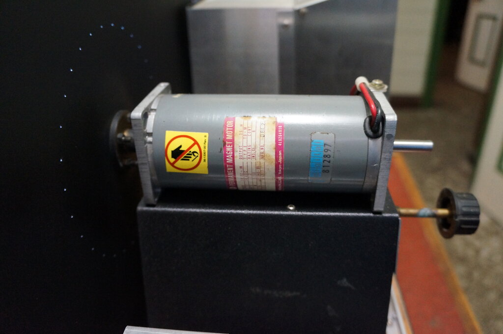
base current to the 2N3055. The motor is a 24V permanent magnet type. Some
adjustment of speed control is provided by a 500R rheostat. Once the motor
speed is in the capture range of the phase detector, the 2N3055 current
will vary as necessary to ensure synchronisation.
Under the motor mount can be seen the filter and 500R rheostat.
Power Supply.
Modern back to back transformers provide
the B+ voltage for the valves. Additionally, a 20V supply feeds the motor
and solid state circuitry.
The main transformer is an A&R type
from a digital trainer produced in the early 1970's. It provides 18V aside,
at a current rating of 2.5A. A full wave centre tap rectifier provides
the 20V DC via a regulator. Regulation was considered important, since
it makes things easier for the synchronising circuitry in case of varying
mains voltage. The regulator uses an AD149 germanium transistor. Being
a PNP transistor, it's in the negative rail. The voltage reference is a
simple zener diode connected to the base.
The 18V AC also feeds a Ferguson PL15/20V transformer in reverse. The output of its 240V winding is full wave rectified and applied to a capacitor-resistor filter. This provides 300V for the vision amplifier, sync amplifier, and the vision lamp. The astute reader may question feeding 18V into a 15V winding, but remember that "15V" is when the transformer is under load, used in the normal way. Off load, the voltage is closer to 17 or 18V - which is what this winding is actually wound for. So, there is no problem with saturation.
A shunt regulated 220V supply is obtained from two series connected 0B2 gas regulators. This feeds the sync separator and motor control cathode follower, to again minimise mains voltage fluctuations affecting the sync circuit.
The 240V secondary of the step-up transformer also feeds a diode-capacitor voltage multiplier to produce 700V. This is required for the initial fluorescent tube ionisation. It's connected to the tube via a 470k so that when the tube conducts, the current from the 700V supply is limited and not just shorted to the 300V supply. A 22M resistor discharges the multiplier capacitors when the circuit is switched off to reduce any shock hazard.
Valve heaters are in three separate series strings and fed from 18V AC. Dropper resistors provide the correct heater voltages.
Test set up with 931A photomultiplier, EF86, and 6SN7.
Using slide projector generated test patterns
was the easiest the way to go, but alas nothing ever came of it. I realised
later that my optics weren't correct for the 931A, and the problems with
the fluorescent tube in the receiver didn't help (see below).
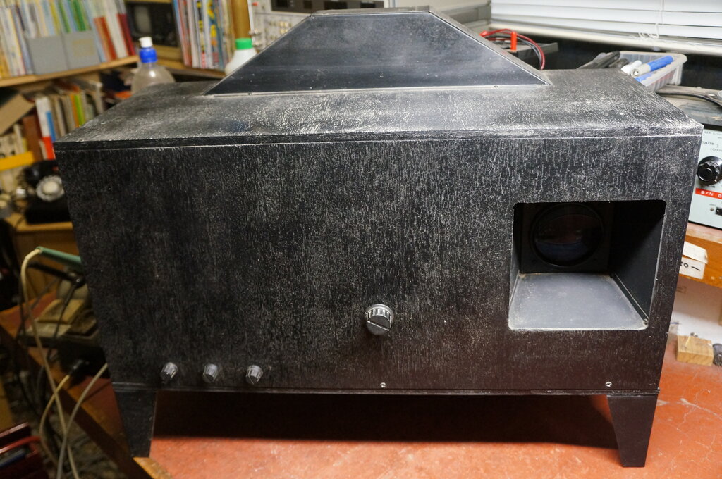
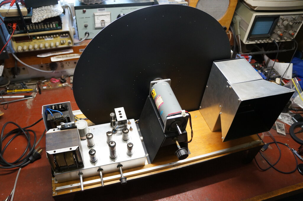
In the meantime, I completed the cabinet
for the transmitter and receiver. Unfortunately, I don't have the skills
to duplicate the Plessey design with its ornate curves and styling, so
it was just a simple plywood cabinet for the receiver, with aluminium covers
for the top and bottom of the disc where it protrudes from the cabinet.
The transmitter cabinet is just a plain box.
Present state of the transmitter. Notice the cobwebs. It's been
sitting there since about 1996!
Project Takes a Break.
During development, the Televisor had
no signal except what could be provided from a function generator. This
provided sync pulses to test the motor control circuit, and the pulses
could be seen in the normal way as a dark bar at the top and bottom of
the raster.
One puzzling aspect was the modulation
of the light source was not perfect. What should have been black was actually
a kind of light brown. I couldn't figure this out - the tube was white
when it was illuminated, and completely dark when it was not.
Some years later I realised what it was.
I had overlooked the phosphor persistence of the fluorescent tube. Yes,
the gas discharge could be modulated up to any likely frequency...but the
phosphor still emitted light for a short time after excitation was lost.
It seemed that the brown colour was that of the phosphor persistence.
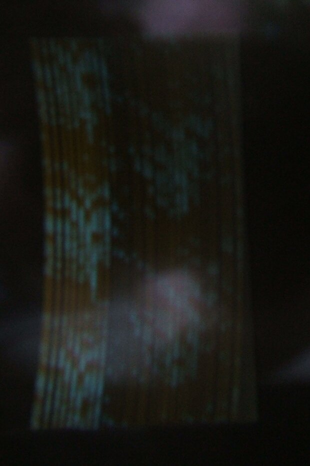
The brown afterglow from the fluorescent tube. There was no locked
picture when this photo was taken.
Eventually, white LED's appeared, then high brightness LED's were appearing in the form of "Luxeon" types, and by around 2008, high brightness white LED arrays started to appear in domestic light bulbs. Thoughts had returned to using one of these instead of the fluorescent tube.
The whole project was shelved (literally!) until March 2022. Once or twice in the intervening years, I had fired up the Televisor in the hope of viewing something, when I found some 32 line files on the internet produced by the NBTV Association.
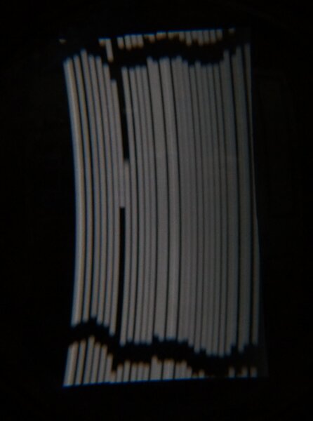
Blank raster with sync pulses. Excellent brightness, colour, and
modulation with the new LED array. Ignore the vertical black lines on line
24 and 23 due to shutter speed.
Unfortunately, the inaccuracy of the hole markings is all too obvious.
LED Array.
First thing was to examine the LED array.
It turned out that the voltage was around 32 - 35, with a current of 350mA
for rated power. Illumination was still more than adequate at 35mA, which
would suit the existing 6EM5 perfectly. In fact, the voltage drop across
the LED array isn't much different to the fluorescent tube.
All that needed to be done was to mount
the LED bulb in place of the fluorescent tube and remove the 700V supply.
Results exceeded expectations. The difference
between the LED and fluorescent tube was nothing short of startling. Modulation
was really good, with proper blacks. Brightness was excellent, and easily
viewable in normal room lighting. The colour is just like a white picture
tube.
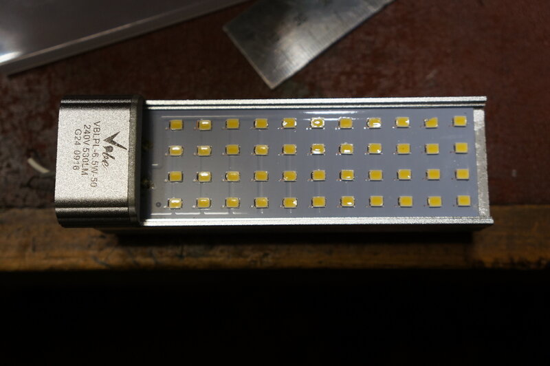
44 LED's in the array.
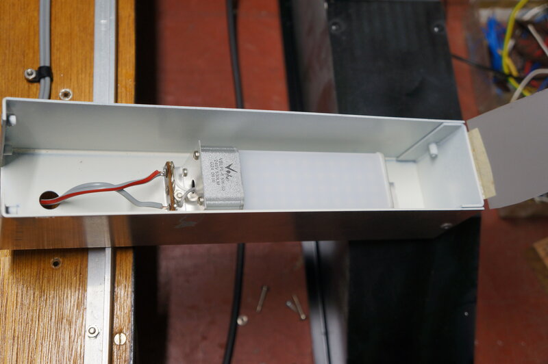
LED bulb with diffuser back in place and mounted in the light box.
Velum panel for further diffusion can be seen attached to top of box.
32 line picture on 30 line disc.
With a renewed enthusiasm I tried the
32 line NBTV files. No wonder I couldn't see anything before - the disc
speed just wasn't fast enough. Analysing the situation, it turns out to
see a 32 line picture on a 30 line disc, the rotation has to be 800rpm
instead of 750rpm.
How this comes about is as follows: Both
the 32 and 30 line systems are 12.5 frames per second. The line frequency
for the 32 line, 12.5 frame/sec. system is 32 x 12.5 = 400Hz. For 30 lines,
the line frequency is 30 x 12.5 = 375Hz.
Now, to see a 32 line picture on a 30
line disc, the line frequency has to be the same to create a recognisable
picture. This is because each vertical line must start and finish at the
same place.
Since our line frequency is now 400Hz,
to see pictures on a 30 line disc it must rotate at 400/30 = 13.33 frames/sec.
This converts into 13.33 x 60 = 800rpm.
It was necessary to increase the disc speed by shorting out the 39R resistor in series with the 500R rheostat, and when that was done I saw my first picture! It was fascinating also to see the sync circuit work for the first time on a real video signal. It locked just as well as when I was using the function generator.
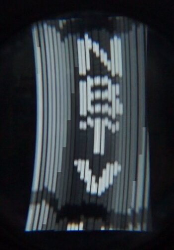
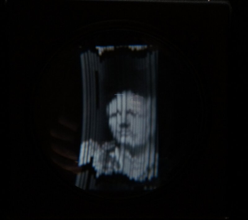
First pictures on Televisor. These are 32 line which will display
on a 30 line disc with slow horizontal rolling.
See these pictures in real time:
Of course, a 32 line picture can't
be displayed properly on a 30 line disc. Since it has to run at 13.33 frames/sec,
the result is the 12.5 frame/sec 30 line picture slowly rolls to the left.
Nevertheless, the slow rolling does not prevent the picture being recognisable.
From the NBTV forum was a software based
standards converter of sorts which did output on 30 lines. Conveniently,
the input source could be the camera in the computer. Finally, I had real
time continuous streaming of a 30 line video signal. A simple but effective
optical standards converter could be had simply by pointing the camera
at a 625 line TV.
22V Regulated Supply.
One result of this was a strong ripple
on the 20V supply. This was severely affecting the pulses from the photo
transistor and pulse amplifier, as well as the sawtooth generator. It was
surprising just how well the motor did lock under these conditions.
To overcome this, I created a separate
22V supply, obtained from a 100k resistor fed from the B+ and 22V zener
diode. This resulted in a perfectly smooth 22V supply for the reference
pulse generator circuit.
Sawtooth Generator.
First thing I wanted to do here was take
the .56uF sawtooth capacitor through a high value resistor to the 220V
B+. Doing so, instead of using the 20V supply, would provide a better sawtooth
waveform. With the 20V supply, the top of the sawtooth is rounded off.
As the capacitor voltage rises, the current through the resistor drops,
and therefore the charge rate slows down.
What is needed is a constant current source
to charge the capacitor. One could use another transistor wired as such,
but an easier method is to use a much higher value resistor, fed from a
higher voltage supply.
It can be seen that for, say, a 0 to 10V
change in capacitor voltage, the current through the charging resistor
will vary little if the supply voltage is 200V. The resistor voltage will
be varying from 190 to 200V. If the resistor is 56k, then the current variation
is only 3.4mA to 3.6mA; a variation of only 200uA, equivalent to 5.8%.
With a 20V supply, and a 3.3k resistor things are quite different. The
resistor voltage drop will now be from 0 to 10V. Across 3.3k, the current
variation is 3mA to 6mA; a variation of 100%.
A rough rule of thumb is to use a supply
voltage of about 10 times the required peak to peak sawtooth voltage required.
Indeed, a 56k resistor from the 220V supply
(actually 200V), produced what looked like a perfect sawtooth, which should
give better locking. To protect the BC548 from 200V, a 30V zener
was connected across its collector to earth. Nevertheless, I managed to
blow two BC548's during experimenting. Since the sawtooth peak is around
11V, the 30V zener will not conduct, except when the disc is rotating very
slowly or not at all.
Sawtooth waveform at the BC548 collector.
19.5V supply.
I had been a bit optimistic with the regulation
for the 20V supply. 18V x 1.4 should give about 24V across the 2000uF filter
capacitor, which means only 4V dropped across the AD149 regulator. That's
only just enough headroom for a simple regulator, but if there's any drop
in the supply voltage, regulation is lost with a subsequent increase in
ripple. The easiest way out of this, short of adding extra turns to the
transformer, was to add a 100uF capacitor across the 20V zener diode. This
dropped the ripple from 1.4Vp-p to 150mVp-p. With the mains supply at home,
the voltage drop across the AD149 is about 3V, which is just adequate.
Correctly speaking, because of the base-emitter voltage of the AD149, the
regulated voltage is actually around 19.5-19.7V.
215V Supply.
It was also observed that the two OB2's
were not regulating. The main B+ was no longer 300V, but around 245V. The
OB2's were seen to light up when the set was first switched on. Once the
set had warmed up, the 220V rail dropped down to around 200V and the OB2's
went out. An active shunt regulator using a 6EH7 was used to replace the
OB2's, and provides a 215V supply. The 6EH7 is wired as a triode. The reference
voltage is the 22V zener previously mentioned, and the error voltage feeds
the grid via the 1M and 100k divider. If the 215V rail increases, so does
the grid voltage. This causes the valve to draw more current and bring
the plate voltage back down.
Motor Hash.
Looking at the 2N3055 collector revealed
a rather spiky waveform with a fair degree of ripple, despite including
a simple filter. The spikes were due to the motor commutator. 10uF across
the collector to earth got rid of those, but there was also a ripple from
the control voltage. This doesn't actually affect the motor's ability to
sync, but I increased the 10uF to 2200uF to smooth it out.
Sawtooth Amplitude.
Thinking back to 1993, I cannot remember
exactly how I chose the component values of the phase detector circuit,
although most of it would have been done experimentally. Seeing only 6.5Vp-p
for the sawtooth at the phase detector input made me wonder; what if the
47k was bridged out and the input increased? We already had 150Vp-p for
the sync pulses, so nothing more should need to be done there. With 11Vp-p
for the sawtooth, the locking was considerably stronger. But now, something
else became evident. It was now 'hunting'.
Anti-Hunting.
What happens is the amount of correction
is so great that it overshoots. Then, the circuit pulls it back, overshooting
again in the opposite direction. The result is a locked picture, but with
the frame moving up and down at a few times per second. The CBS colour
wheel circuit had an 'anti-hunt' control which hadn't been necessary before.
Now that hunting was present, I tried it out, and yes, it fixed the problem.
It relies on the slowly varying error
voltage at the motor being superimposed on the sawtooth voltage. If the
amount of error voltage fed back is carefully chosen, the over correction
causes just the right amount of negative feedback, which stabilises everything.
A resistance of 68k from the 2N3055 collector to the sawtooth input of
the 12AU7 was about optimum. As the resistance was adjusted towards the
correct value, the picture suddenly locked solid.
The resistance was fairly critical, so
it would need a preset adjustment (as with the CBS circuit), but also the
positive DC component coming from the 2N3055 created a phase shift, moving
the picture slightly upwards. Of course, this can be compensated for simply
by adjusting the phototransistor position.
Critical Damping.
Line oscillator AFC circuits in electronic
TV receivers use a critical damping circuit to prevent hunting, so before
installing a 100k anti-hunt preset, I decided to try this alternative.
It not only worked, but it was simpler and less critical with component
values. Also, there was no picture shift to be corrected. A 39k resistor
in series with a 10uF capacitor at the grid of the 6J6 cathode follower
worked nicely. There is a mathematical formula for critical damping, which
as I remember from my tech days was relatively complicated. It's easier
to work it out experimentally.
Motor Control and Anti-Lockout.
The original 500R rheostat and 39R+47R
resistors did not provide the range of motor speed required for both 750rpm
and 800rpm operation. I would have liked to use a 1k rheostat, but had
none that would fit in the existing space. However, the speed can also
be manually adjusted with the 2N3055 base current on its own, and so the
circuit was modified to suit. A much greater range of adjustment is now
available with the 500R rheostat.
A characteristic of doing it this way
means the motor speed now is entirely dependent on the 6J6 cathode current.
This showed up as a problem when, if switching the Televisor on from cold,
the motor would never come up to enough speed so that the sync circuit
could lock it. The 6J6 grid voltage was negative during warm up, which
meant little 2N3055 base current flowed. The way around this was simply
to connect a diode between grid and earth so it could not go negative.
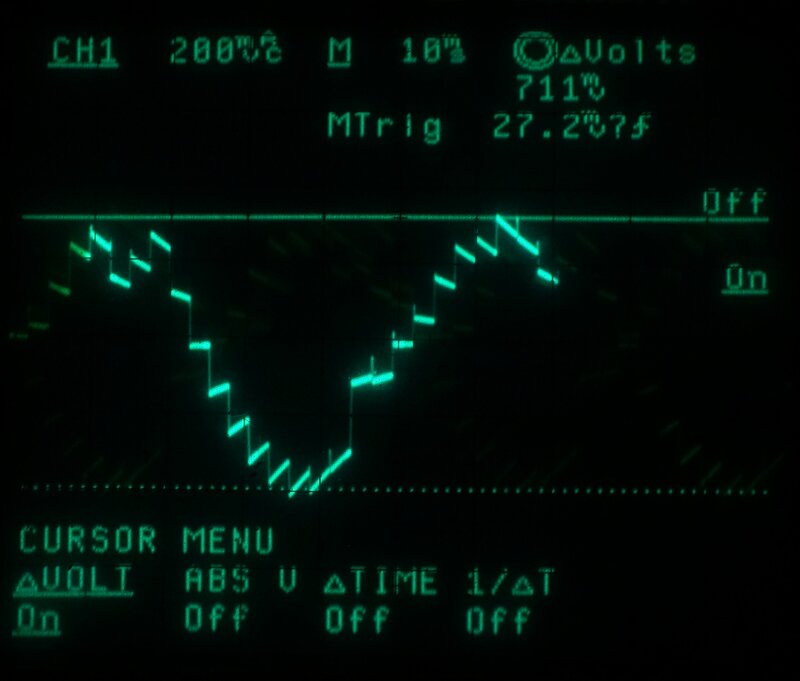
Control voltage at 6J6 cathode. Voltage varies continuously to keep
motor locked to sync pulses. The 375Hz component is ignored by the motor.
Elimination of the Sync Amplifier.
The initial design was for two separate
video amplifiers; one to drive the vision lamp with a variable input attenuator,
and another to drive the sync separator unaffected by the vision lamp amplifier
gain.
Looking at the circuit now, I questioned
the need for duplication. If the gain control was moved to the 6EM5 grid,
then the one 6BL8 amplifier could also feed the sync separator.
The modification worked perfectly, and
the gain control didn't need to be moved to the 6EM5. The sync separator
works so well that anything from 70mV input to at least 1V provides a clean
sync pulse.
The sync is clean over the normal contrast
range, from a barely visible picture to one which is grossly overloaded.
Heater Supplies.
With the elimination of one 6BL8, the
heater strings were wired more efficiently. The two 6J6's remained on their
original circuit, but the 6EM5 circuit now included the remaining 6BL8
and the 6EH7. It was rather wasteful to have the 6.3V 800mA heater of the
6EM5 all on its own through a resistor to 18V. Strictly speaking, there
should be a 50mA shunt resistor across the 6EH7 heater, but the tolerances
of the heaters were such that this wasn't needed. It would need to be checked
if any of the valves were to be replaced. The 12AU7 remains heated from
the 19.5V supply through its own 56R resistor, since it draws only 150mA.
Sync Switch.
Now that 30 line pictures were available,
a remaining control needed to be included - which I had suspected all along.
Because the Baird format uses only line sync pulses, there is no automatic
control over the frame phasing. The picture could be split vertically down
the middle, or anywhere else in the frame, depending on where the start
of the frame was when the motor locked. The Baird instructions say to gently
get the picture out of sync, and wait for the frame phasing to be correct
before locking it back in. My circuit, being an electronic AFC type, has
a greater capture range than the phonic wheel in Baird's Televisors, so
this method is difficult. Instead, the sync can be disabled until the picture
floats into position, and then restored. Thus, another switch is required.
I had hoped to swap the existing 'normal/invert' vision switch for a 4
position version, with the adjacent positions being used to disable the
sync. Unfortunately, such a switch was too big to fit, so a separate switch
was added. It shorts pin 1 of the 6J6 to earth.
Nipkow Disc.
Unfortunately, due to marking out the
disc holes by hand, accuracy is less than optimum. The horizontal spacing
from the disc centre is just acceptable, but the angular vertical displacement
is not, particularly for lines 23 to 30. I was aware this might happen,
so both the transmitter and receiver discs were bolted together when drilled.
The idea is the errors would cancel out. The results remain to be seen.
For now, it means 30 line pictures obtained
from elsewhere are distorted badly for the last seven lines. While the
disc errors could be corrected for use with standards converter signals,
both discs will need the same correction if I'm to use my own transmitter.
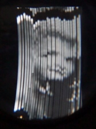
Yours truly shown in 30 lines.
Another problem is my discs have ended
up with a 5.2 :3 aspect ratio, instead of Baird's 7:3. This came about
because although the disc holes were correctly spaced at 12 degrees in
the angular plane, I used a 1mm drill for the holes. As a result, the horizontal
hole spacing was further apart than it should be for the 20" disc. I should
have used a smaller hole size.
The end result is that Baird pictures
tend to be a little squashed in terms of height.
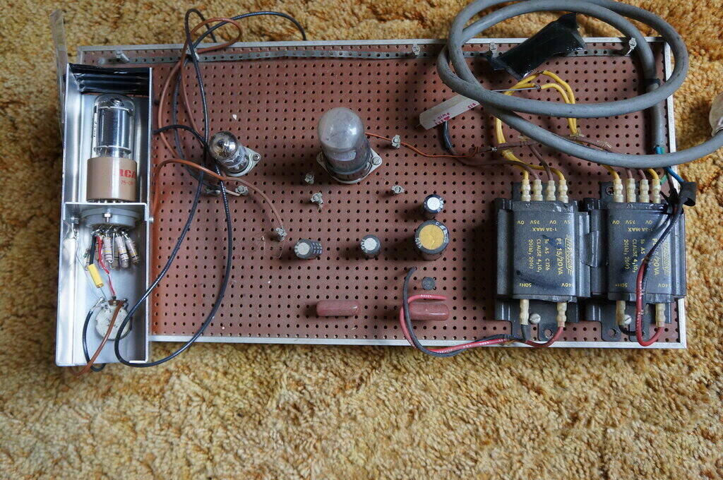
Improved circuit, March 2022.
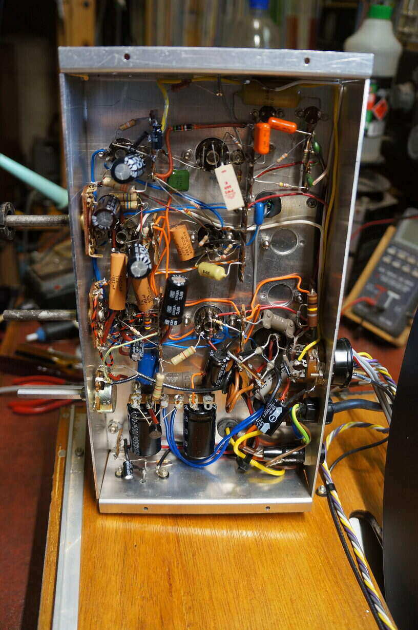
Under the chassis.
Rear of Televisor shows light box for the vision lamp, and sync
lamp.
Some Measurements:
AC:
Got a Baird Televisor for Sale?
I'd be interested to hear from you. Yes,
I am aware of how much they are worth, so a replica is more in my price
range. (I'd rather buy a Televisor than a car...)
There were some excellent replicas built,
apparently 12 of them, which I would be equally delighted to own:
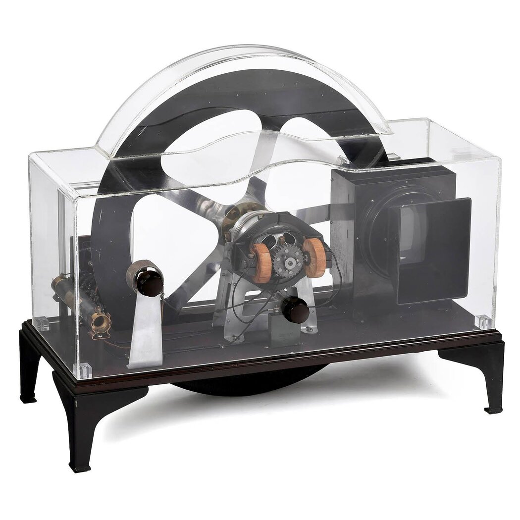
One of the replicas with perspex case.