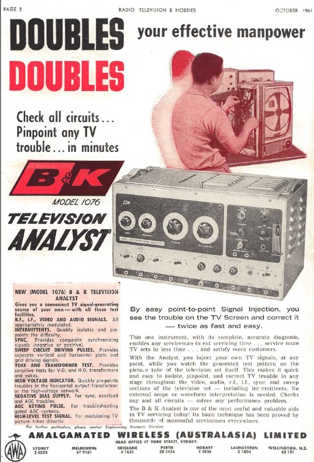
The B&K 1076 Television Analyst was a very popular test instrument from the monochrome era. They were made in Chicago by B&K Instruments and were released around 1961. Since the 525 line monochrome TV system is very similar to the western European CCIR 625 line system, the 1076 was modified slightly under the model designation of 1076-ES and sold there, and in Australia. Here, the 1076-ES was distributed by AWA. The only modifications done were to provide a power transformer for 240V mains, retune the sound IF oscillator to 5.5Mc/s (instead of 4.5Mc/s) and alter the frequencies for the VHF output channels. The 1076-ES sold in Australia has different VHF channels again to those in Europe or the U.S.
From Radio, Television & Hobbies, August 1961.
What does the Television Analyst
do?
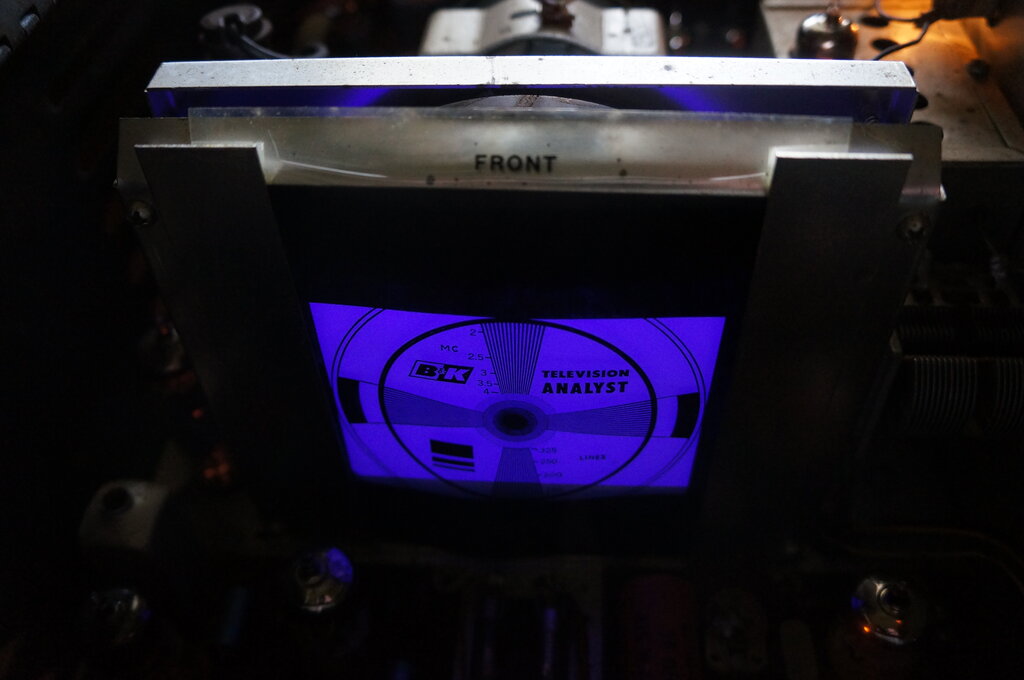
Central to the 1076 is a flying spot scanner,
which generates a test pattern from an acetate slide. From this pattern,
all the usual picture geometry adjustments can be performed, as well as
giving an idea of the receiver's video performance. Several other slides
are included which are intended for setting up colour receiver convergence.
The test pattern is available as a composite
video signal of either positive or negative going polarity. It is also
modulated on an RF carrier, tunable from 20Mc/s to the high band VHF channels.
In this way, the entire signal path from aerial terminals to the video
amplifier can be tested.
The 1076 also provides sync pulses, also
positive or negative going. These are used to track down sync pulse faults
in the receiver under test - provided of course it is displaying the test
pattern from the 1076.
For testing AGC faults, a variable negative
supply is made available.
The deflection system in the TV can also
be tested since the 1076 provides grid drive signals for vertical or horizontal
stages. In addition, plate drive signals are also available which can substitute
for the output valves in the set under test.
A shorted turns tester is provided for
testing line output transformers or the horizontal section of a yoke. For
testing the vertical section of the yoke, a terminal is provided for feeding
6.3V into the winding.
There is also a simple leakage tester
provided.
Television Analysts have not always been
relegated to TV servicing. Since one can make up their own slide, any desired
image can be transmitted throughout a closed circuit TV system. One example
is displaying a printed list of departure times, shown on receivers located
around an airport terminal.
Although of no relevance to Europe and Australia, a colour test signal is provided. When the 1076 was developed, the only colour system in actual use was the NTSC 525 line system in the U.S., and this is naturally what the 1076 is designed for. Since the colour subcarrier for 525 lines is 3.58Mc/s and that for 625 lines is 4.43Mc/s, it's obvious that it won't provide colour for 625 line sets. Furthermore, the method of obtaining the test pattern won't work properly on PAL even if the crystal is changed. There were tentative proposals for using NTSC in 625 line countries at the time, so it can be surmised that the intention was to simply change the crystal (if necessary). This is probably why the colour circuitry was not omitted from the ES version. In any case, the same PCB which contains the colour circuitry also contains the monochrome video circuit.
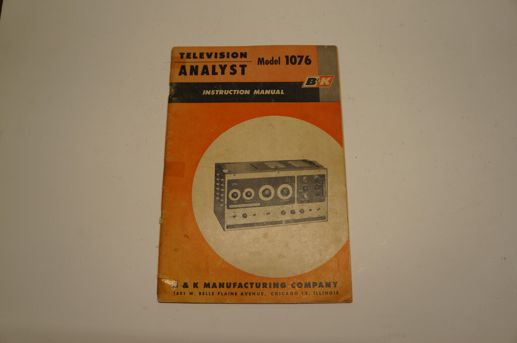
It is a very comprehensive instrument with the manual being 48 pages. Rather than repeat the contents of the manual in this article, the reader is advised to download and read it for a full understanding of the 1076's capabilities.
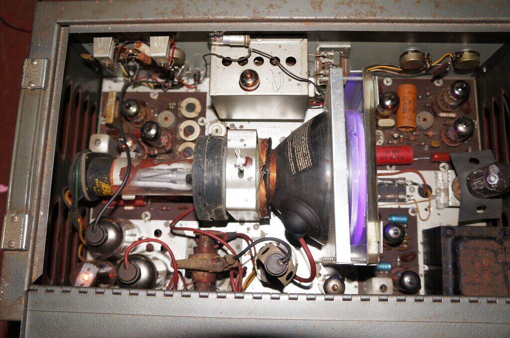
The CRT scans the slide, the light passing through being projected
onto the photo multiplier, visible at the right.
The instrument is in a steel cabinet, with a lift up lid to allow slide changing. It is hard to imagine the nanny state allowing such a device in the modern day, since plenty of high voltage terminals are immediately accessible, to say nothing of the exposed fuseholder carrying the 240V mains.
The picture tube phosphor emits in the UV spectrum since this is
where the photo multiplier is most sensitive.
Flying Spot Scanner.
Since this is the heart of the instrument,
and that those not familiar with TV transmission methods may be curious,
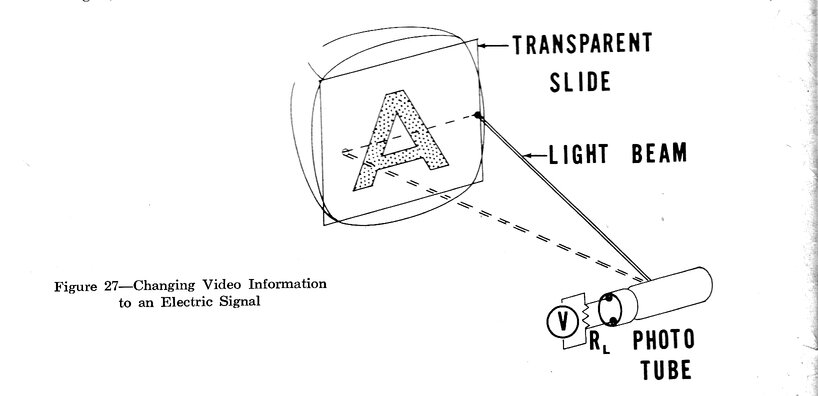
a brief description will be given first. Flying spot scanning goes back
to the days of mechanical TV. It is a very simple way to generate an image
without using a camera tube as such. All that is required is a light source
which does the scanning, and a photo tube. The light source is passed through
a slide (or film) and as it passes through the light and dark areas, the
photo tube picks up the fluctuating light levels.
Principles of flying spot scanning.
The light source is typically a picture
tube displaying an unmodulated raster at the required line and field rates.
It should be clear therefore, that if the signal from the photo tube modulates
a picture tube which is being scanned at the same rate as that of the light
source, then a picture will result. In the mechanical TV era, the light
source was usually an arc lamp with the raster scanned by a Nipkow disc
or mirror drum.
Flying spot scanning is not limited to
slides or film. The light can be reflected off objects instead. However,
this requires more sensitive photo tubes and a brighter light source. It
was used extensively with mechanical TV since an arc lamp could be used.
Once electronic camera tubes had been developed, flying spot scanning was
relegated to slides and film.
In the 1076, the picture tube is a 5"
5BKPV1, a tube unique to B&K. The phosphor primarily emits in the ultra
violet spectrum since the photo tube is most responsive to this wavelength.
The photo tube is actually a 931-A photo multiplier which has considerably
greater sensitivity than a simple photo tube.
Now, we will look at the design of the Television Analyst, and the rest of the techniques are probably more familiar to most readers.
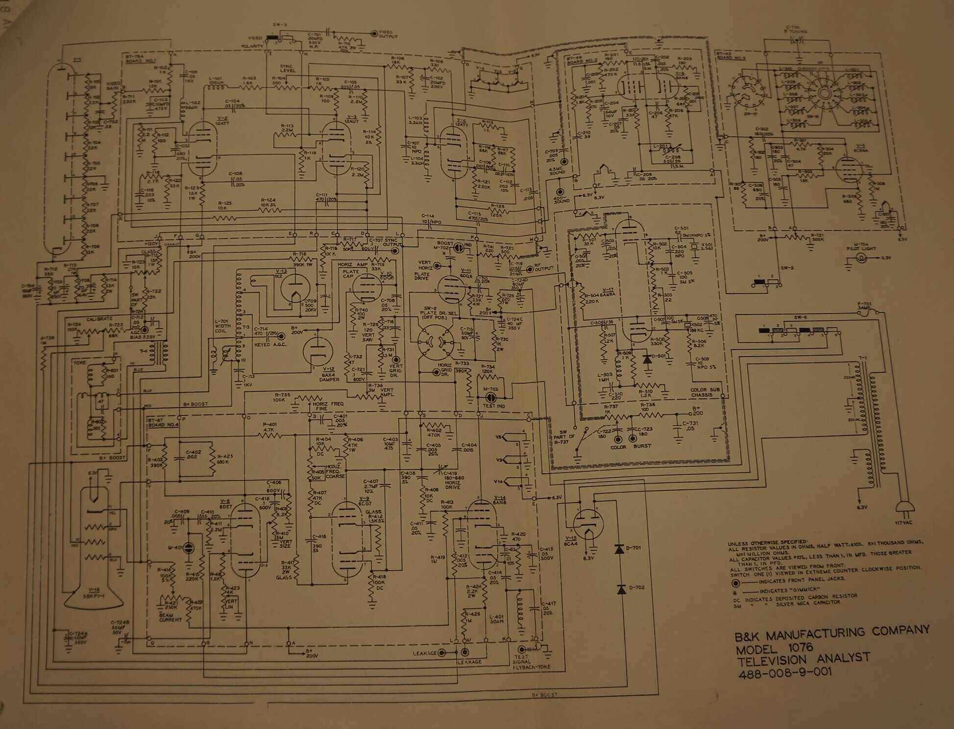
Circuit of the B&K 1076 Television Analyst.
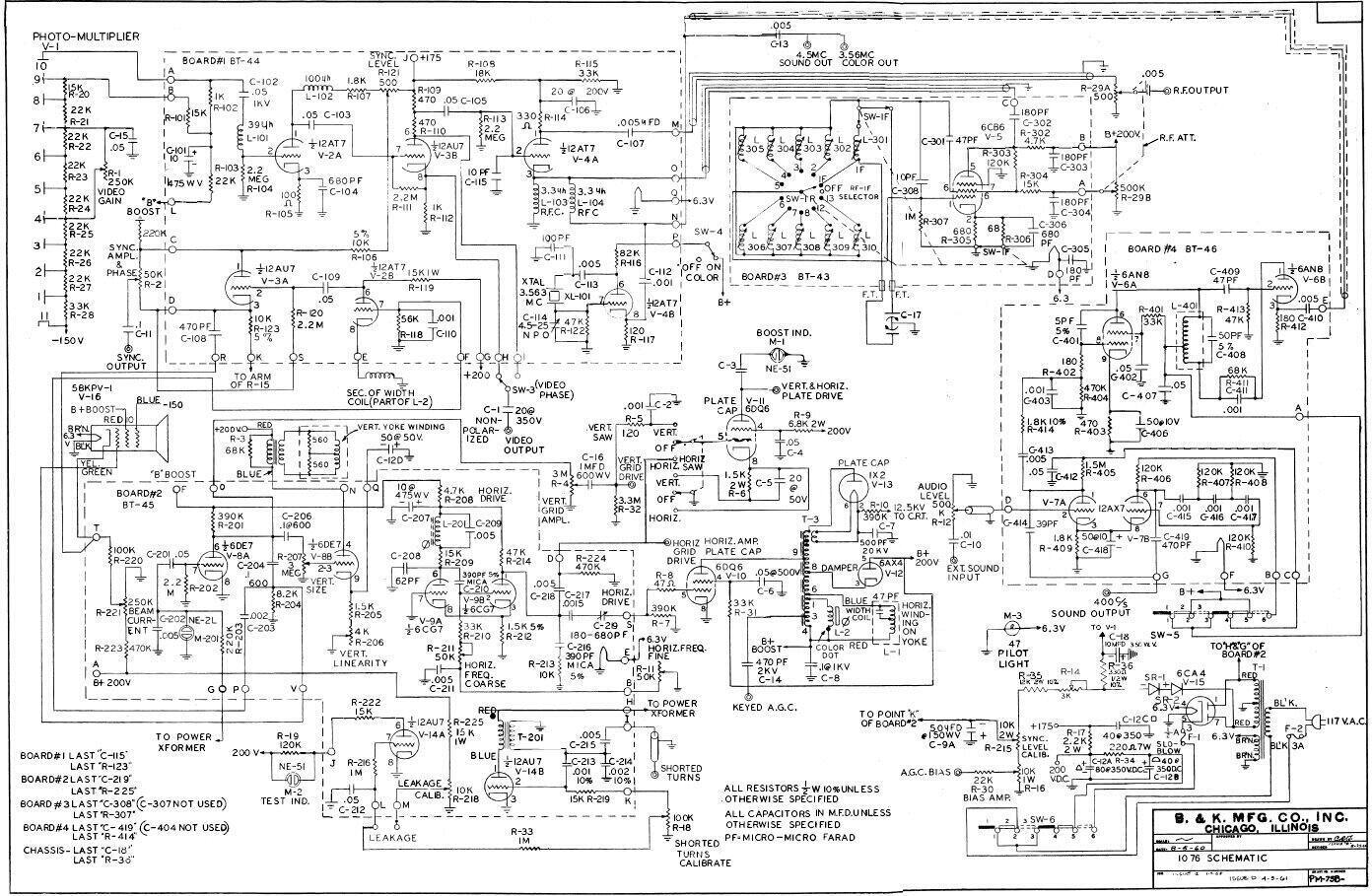
There are at least three versions of the 1076 with different circuits.
This circuit is closest to my two instruments.
As I recently discovered, the circuit which I had obtained back in 1993 was not actually the same as the two 1076's I have. Neither was the circuit that came with the second 1076. Luckily, a search on the internet did come up with the right circuit, although during the restoration work, I found that it too had very slight differences. The circuit closest to my instruments is presented above.
The 5BKPV-1 and Deflection Circuit
- Board BT45
We will start with the flying spot scanner
and its raster generation. The 5BKPV-1 is an electromagnetically deflected
CRT with a standard size neck and base. There is no published data, since
it is unique to B&K, but appears to be of 90 degree deflection.
Presumably, the tube is not aluminised, since a bent gun is used with an
ion trap. EHT is 12.5kV, according to the circuit diagram. According to
the service instructions, the cathode current is 75uA. As the CRT is to
only provide a steady light source, the cathode is not fed with any signal.
The grid is fed with a blanking signal during vertical retrace.
The line (horizontal) deflection is like
any domestic set, using a 6CG7 oscillator which drives a 6DQ6 as the line
output valve. The horizontal output circuit is conventional using a 6AX4
damper diode. EHT from the overwind is rectified by a 1X2 in the usual
way.
The only difference is that the oscillator
is free running. The frequency is user adjustable by the panel mounted
control R-11. Since the line sync pulses from the Television Analyst come
from this oscillator, it follows that the TV under test will be synchronised
to it, and the actual frequency is not important within limits. As per
domestic sets, a stabilising coil, L-201, is fitted. It tends to pull the
6CG7 multi-vibrator towards its resonant frequency (15,625c/s for 625 lines
or 15,734c/s for 525 lines).
The field (vertical) deflection uses a
6DE7, a twin triode with dissimilar sections. One triode generates the
sawtooth, and the other is the output. At first glance, the circuit looks
like what one would see in a domestic TV set, but in actual fact there
is no oscillator. Instead, the sawtooth is generated from the mains frequency.
A neon lamp clips the 50 (or 60) cycle sine wave from the power transformer
secondary, and uses this to drive one of the 6DE7 triodes. In the plate
circuit of this triode is the usual sawtooth forming circuit based around
R-201 and C-204.
Thus, the vertical frequency is locked
to the mains. The output stage is conventional, and uses bias adjustment
to set the linearity.
At this point the 5" CRT is displaying a raster, so the next thing to look at is the video circuit.
931-A and the Video & Sync Circuits
- Board BT44
The 931-A is a nine stage photo multiplier
tube. It looks like an octal valve but has an 11 pin base.
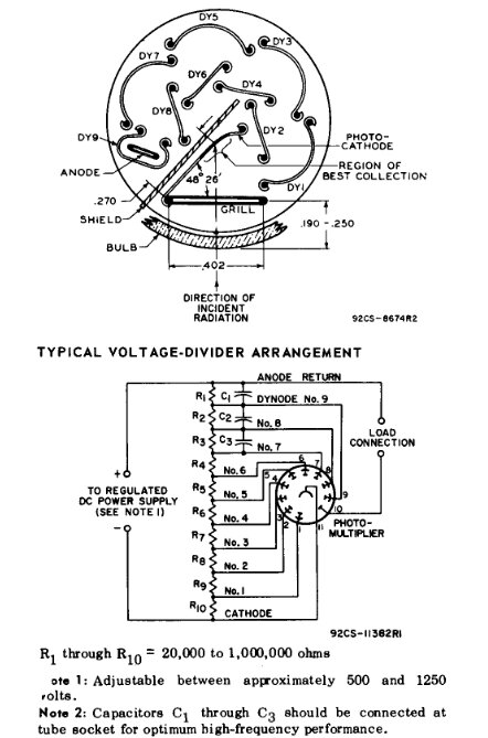
Basic configuration of the 931-A.
Each stage of the photo multiplier is called
a Dynode. Each dynode is connected across a voltage divider in succession,
so that the adjacent dynode receives a greater voltage. The light striking
the photo cathode causes an electron flow; the electrons being directed
to each successive dynode. In basic terms, the electrons leave each dynode
with greater acceleration than the previous, so by the time the anode is
reached, the electron flow is much greater than it was at the cathode.
The video output directly from the 931A
used in the 1076 is about 500mV p-p. This is much greater than if an ordinary
photo tube was to be used, and simplifies the following video stages.
The first circuit discrepancy appears here with the video gain control. In both the units I have, the voltage to dynode 9 is varied by a 250k pot. On the circuit shown, gain control is obtained by reducing the voltage between dynodes 4 and 7. The later circuit shows it as per my units.
Incoming video from the 931-A feeds into the grid of V-2A, one half of a 12AT7. This is just a resistance coupled amplifier, with peaking chokes and a low value of plate resistor to improve the frequency response. The signal passes into the phase splitter stage, V-3B, half of a 12AU7. This is a standard circuit with equal plate and cathode load resistors. In phase signals are taken from the cathode, and out of phase signals from the plate. Either of these is selected by the polarity switch on the front panel, and coupled to the outside world via a non-polarised electrolytic capacitor, C-1.
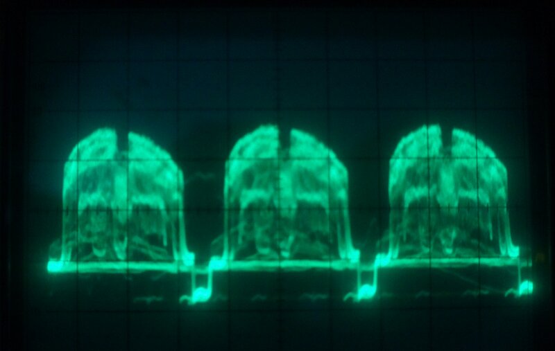
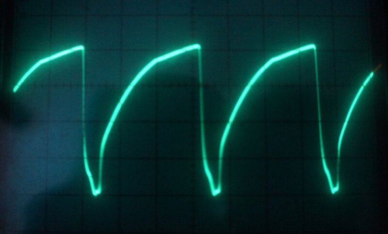
Video output at line rate.
RF Modulator.
In addition to feeding the video output
terminal, the video signal also feeds the RF modulator, V-4A, half of a
12AT7. Video is fed into its grid, while RF comes in via the cathode. The
plate load is R-114 and is the source of RF output. Effectively,
the triode is working as a grounded grid RF amplifier, but since the grid
is fed with the video signal, the RF at the plate is modulated by it. A
500R pot forms a simple output attenuator.
The next circuit discrepancy is to do
with the modulator video feed. Here, the circuit shows the plate load of
the phase splitter being comprised of two 470R resistors (roughly equal
to the 1k cathode resistor). The modulator is fed from the junction of
these two resistors, since full amplitude is not desired. However, in my
units, and what I assume to be the later circuit, the resistors are 1k
and 100R, arranged so the modulator gets more drive.
Sync Amplifier.
Final to the video circuit is the sync
pulse amplifier, the first part of which is V-2B, the other half of the
12AT7. It mixes the line and field sync. Line pulses come into the cathode
from a secondary winding on the width coil. Vertical sync comes into the
grid from the vertical sawtooth generator. Therefore, across the plate
resistor, R-119 is a composite sync signal.
V-3A, half of a 12AU7, is wired as a phase splitter similar to that used for the video output. Again, equal plate and cathode resistors are used; this time 10k. Instead of a polarity switch, a 50k pot is used to obtain a completely variable transition from negative to positive pulses. With the pot in centre position, the negative and positive outputs cancel, and output is at minimum. The sync output from the pot wiper is taken to the front panel terminal via a 0.1uF capacitor.
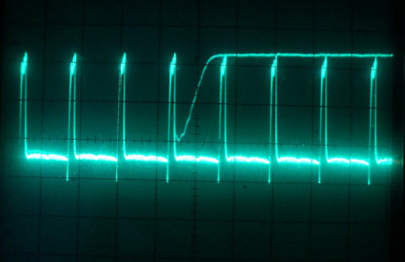
Sync at line rate.
The plate load of the sync phase splitter and the video amplifier are shared by the sync level adjustment pot, R-121. By this means, sync pulses are injected into the waveform from the photo multiplier, thus forming the composite video signal.
Colour Generator.
Also on board BT-44 is the colour generator.
This is a simple crystal oscillator based around V-4B, half of a 12AT7.
Output is taken from the cathode, out to a front panel terminal, and is
also fed into the RF modulator. Note that the crystal frequency is not
3.58Mc/s, but is 3.563Mc/s. The principle of operation is that being lower
than the colour subcarrier frequency by the line frequency, a rainbow pattern
is formed. This occurs because there is one cycle per line difference between
the 3.563Mc/s oscillator and the 3.58Mc/s oscillator in the TV. This creates
a 360 degree phase shift over each line. Since the hue is dependent on
phase shift, it follows that the hue will change across the colour spectrum
as the line is scanned. Since this repeats on every line, the result is
a vertical rainbow.
Sound Generator - Board BT-46.
The 1076 includes a 400 cycle audio oscillator,
the output of which is available directly for testing audio circuits. It
also feeds an oscillator and FM modulator at 4.5Mc/s (1076) or 5.5Mc/s
(1076-ES). Additionally, input is provided from external audio sources.
The 400 cycle tone is generated by a phase
shift oscillator based around V-7B, half of a 12AX7. The other half of
the 12AX7 is a simple voltage amplifier fed from the external audio input.
These two signals are mixed and fed via C-413 into the modulator. When
using the external audio source, the 400 c/s tone can be switched off by
removing the B+ to V-7B.
The sound IF oscillator, tuned to 4.5Mc/s
or 5.5Mc/s, uses the triode of a 6AN8 (V-6B) in a Hartley circuit. Output
is from the cathode, and feeds a terminal on the front panel, as well as
being injected into the RF modulator.
In order to produce FM, the reactance
valve, V-6A is shunted across the tuned circuit. It uses the Miller effect.
By adjusting the grid voltage, the capacitance between plate and grid (C-401)
can be made to appear smaller or larger. Therefore, the capacitance of
V-6A changes at the audio rate, and since it is across the tuned circuit,
creates FM.
An interesting feature is that both the
sound IF and colour signals are connected together at the same output terminals,
as well as simultaneously feeding the modulator through the same input.
RF Oscillator- Board BT-43.
A 6CB6 pentode operates as a two terminal
oscillator, with the coils shunt fed from the screen grid and fed back
into the control grid. The front panel channel selector switch selects
any one of the tuned circuits which cover the VHF channels. In the IF position,
the coil is connected across a variable capacitor, which allows the user
to tune this circuit to between 20 and 45Mc/s. This accommodates all modern
receiver IF's. In the case of Australian conditions, it will tune up to
Ch. 0.
It was mentioned previously that the RF
output from the modulator was attenuated by a 500R pot (R-29A). Ganged
to this is a 500K pot (R-29B). This is connected across the B+ and the
wiper feeds the screen grid of the 6CB6. Thus, as the output is reduced
by adjusting the pot, the screen grid voltage is also reduced. This provides
a smoother control action of the attenuator.
Output of the oscillator is from the plate,
and feeds the modulator via C-302.
Test Circuits.
So far, we have everything necessary to
produce a test pattern and transmit it into a TV set. But there's more
to the 1076 which will now be described.
AGC Keying Pulse.
For testing AGC circuits in sets with
gated AGC, a capacitor isolated horizontal pulse is provided from the line
output transformer.
Vertical & Horizontal Grid Drive.
These two signals can be used to substitute
for the drive to the horizontal or vertical output valves in the TV set,
thus determining whether the oscillator or output stage is at fault.
The horizontal drive comes from the same
point which drives the grid of the 6DQ6 used for the flying spot scanner.
The amplitude is not adjustable, but as a go/no-go test this is not important.
Just about all line output valves have similar drive requirements.
Vertical grid drive comes from the vertical
sawtooth generator triode (V-8A), and is made available via a 3M pot to
adjust the amplitude.
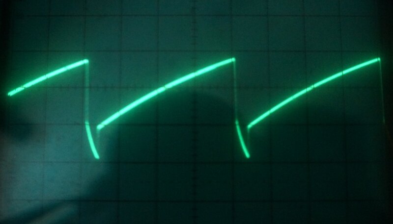
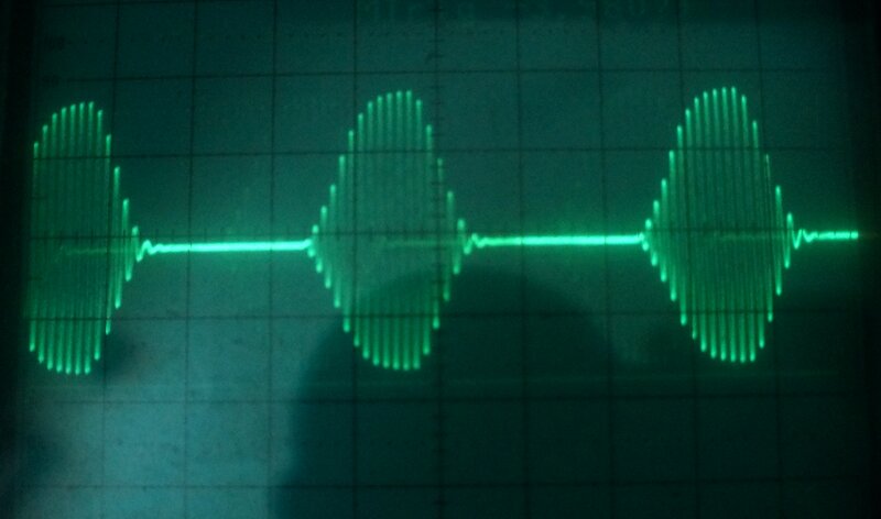
Vertical grid drive and horizontal grid drive waveforms.
Vertical & Horizontal Plate Drive.
A separate 6DQ6 (V-11), is made available
for substitution for either the horizontal or vertical output valves in
the TV set. For fault finding, it restores deflection if the relevant oscillators
or output stages are inoperative.
The plate terminal connects directly to
a front panel terminal and thence to the required connection in the set
under test. There is a three position switch which turns off this 6DQ6
simply by disconnecting the cathode, but when it is required, provides
grid drive from the same points described above. It is unusual to use the
6DQ6 as a vertical output valve since it is something of overkill, but
in this test application makes sense. When used as such, a cathode bias
resistor is switched in (R-6) to get the 6DQ6 operating in class A. For
horizontal output, the cathode is earthed as normal, and the valve operates
in class C.
There are two things which attracted my
attention to this part of the circuit. Firstly, it is assumed that for
most of the time the 1076 is operating that this feature won't actually
be used. The problem is that leaving the 6DQ6 heater running all the time
with no cathode current, it's possible that cathode poisoning could occur.
Ideally the switch should allow the heater to be turned off when not in
use. Alternatively, if one remembers to do so, occasionally swapping this
6DQ6 with that of the flying spot scanner would prevent the problem.
Secondly, the 6DQ6 can be operated with
no plate voltage when the switch is in horizontal or vertical drive, but
with nothing connected to the plate terminal. Pentodes and tetrodes do
not like operating with no plate voltage, because the screen then dissipates
the current that would otherwise be carried by the plate. In this instance,
one would have to assume that the screen resistor, R-9, is high enough
to prevent the screen being overloaded when there is no plate voltage.
It's easy to imagine a 1076 operating
day in day out generating workshop test patterns, and someone hasn't bothered
to check the 6DQ6 is switched off unless it's actually being used.
An interesting feature is the B+ Boost indicator light. This is simply a neon bulb coupled to the 6DQ6 plate via stray capacitance, which happens to be an insulated tag mounted on the plate terminal. Assuming the boost circuit in the TV set works, the 6DQ6 plate voltage will be high enough so that the neon will illuminate.
This cathode poisoning problem could also be applicable to the colour oscillator, since when it's switched off, the B+ is removed, and the same applies to the audio oscillator and sound IF oscillator. It would have been an easy thing to prevent by simply allowing a small amount of cathode current to always flow, but not enough to make the stage operative.
Shorted Turns & Leakage Tester.
The shorted turns tester is based around
an oscillator formed by V-14B, half a 12AU7, and transformer T-201. In
the normal way, due to grid rectification, the grid of the triode becomes
negative when the circuit oscillates. The coil to be tested is effectively
connected in parallel with the grid winding of T-201. If the coil under
test has a shorted turn, T-201 will be loaded down so much that the circuit
stops oscillating. When this happens, the grid is no longer negative.
V-14A is the other half of the 12AU7 and
is used to drive a neon bulb. Its grid is fed from a portion of the oscillator's
grid voltage. This is adjustable by pot R-18, designated "Shorted Turns
Calibrate". The pot is adjusted so that V-14A is cut off and the neon does
not light.
When V-14B's grid voltage drops because
the coil under test has shorted turns, V-14A's grid voltage is no longer
as negative, causing the triode to conduct and turn on the neon bulb.
Interestingly, the oscillator circuit B+
is AC from the transformer secondary. This means oscillation occurs only
on the positive cycles.
The leakage tester also makes use of V-14A
and the same neon indicator. As before, the triode is biassed off by R-18
so the neon does not light. The suspect component is connected between
a positive voltage and the grid of V-14A. If the component is leaky, it
follows that the negative grid voltage will be cancelled out, causing the
neon to light. The positive voltage comes from pot R-218, fed from B+ via
R-225. It is set so the neon lights if leakage is below 10M.
AGC Bias.
For diagnosing AGC faults, a variable
negative supply is available from the wiper of pot R-215. This provides
up to -50V and can be used to over ride the AGC voltage in a TV set. For
example, if the AGC in a faulty set is too high or too low, the signal
will either be cut off or the set will be overloading. This AGC bias source
can be connected into that of the faulty set and if normal operation is
obtained, it confirms that the AGC circuit in the set is at fault. The
bias source is also useful for aligning video IF stages where the AGC must
be set to a specific voltage.
Vertical Yoke
A simple test for a vertical yoke is to
feed 6.3V from the heater line into it. Because of the sine wave, the picture
will have very poor linearity with fold over, but it will demonstrate that
the coils are continuous with no shorted turns. For this feature, a yoke
test terminal is provided which is simply connected to the heater supply.
This is a useful feature for testing sets where there is no suitable 6.3V
supply available; i.e. series heater circuits.
High Voltage Tester.
Stored on a front panel clip is a neon
bulb for the purposes of testing for EHT radiation and line output activity.
The neon bulb is not connected to anything but is physically attached to
an alligator clip. As is well known, simply placing a neon bulb near an
EHT transformer or line output valve plate connection will cause it to
light, if the stage is working correctly.
Power Supply.
For something of U.S. design, the use
of the European 6CA4/EZ81 rectifier is unusual, whereas all the other valves
are ordinary U.S. types. The power supply is conventional with a power
transformer, a full wave rectifier, and RC filtering. B+ is 200V.
A negative supply is also provided for
the AGC bias output, the photo multiplier, and the sync pulse phase splitter.
This comes from a half wave selenium rectifier.
Although not confirmed, it appears that
this is a later version of the 1076. I say that because the instruction
manual which I have for my second unit is dated 1962. It specifically mentions
the video amplifier plate load being two 470R resistors - which tallies
up with the first circuit diagram in this article, dated from 1960.
This later circuit has a few modifications.
In particular:
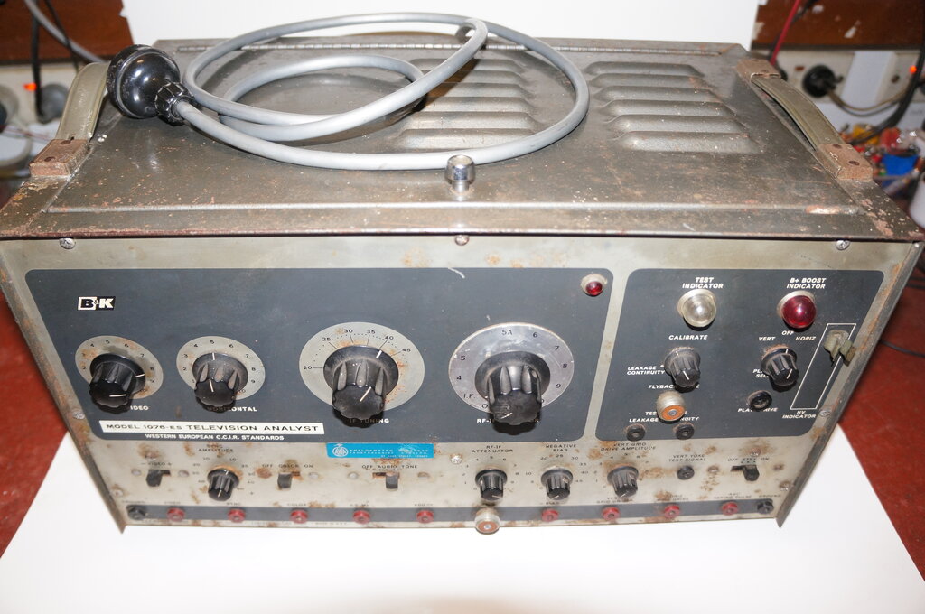
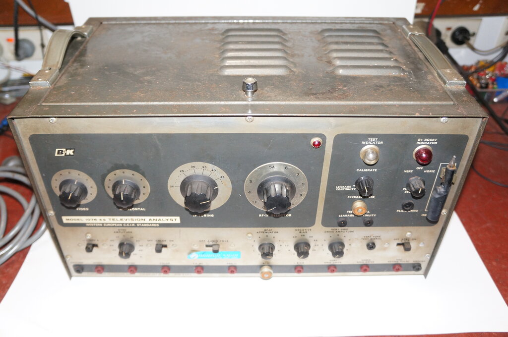
Restoring the 1076-ES (First Unit).
My first 1076-ES is shown in the opening
photo. As can be seen, cosmetic condition is a bit worse for wear with
some surface rust on the cabinet and front panel. As it transpired, it
appears to have had a lot of use; the kind of instrument that was used
every day.
Back in 1993, I replaced some of the resistors
and paper capacitors to get the unit working. Even so, it wasn't perfect,
with the main problem being poor vertical linearity.
To the present time, July 2021, I felt
enthused to do a proper job and make this into an instrument that could
be reliably used.
By now, the rubber insulation inside the
mains flex was becoming hard and brittle, so this was the first thing to
replace.
Each function of the 1076-ES was tested and made good before moving onto the next. Although it was never intended, the video output will drive a 75R load, and so a monitor was connected to this.
Board BT-44.
The video was poor in that the resultant
picture was unstable with a lot of vertical jitter. The gain control was
also very abrupt. After replacing C-102, and adjusting the sync injection
level, this was improved. The gain control was noisy just at the optimum
spot, so was squirted with CRC. This helped, but ultimately the pot should
be replaced.
All the resistors in the 931-A voltage
divider were high to a lesser or greater degree and were replaced. For
example, R-27 instead of 22k was measuring 75k.
R115 in the RF modulator supply had risen
from 33k to 64k.
It was also found that the particular
931-A was giving out only 200mV of video whereas the manual states it should
be 500mV. Trying the 931-A from my other 1076 and also a spare restored
the 500mV, confirming the original might be weak. However, perfectly acceptable
results were obtained once all the other faults had been fixed, and the
original was retained.
The sync output was poor with positive
going pulses much weaker than those negative going. This turned out to
be R-106 drifting from 10k to 5k. It's unusual for a resistor to drop in
value but here it was. Replacing it fixed the problem, and both positive
and negative sync pulses were as they should be. I noticed that the sync
output adjustment pot, R-2, had been replaced sometime in the past.
Although not of importance, while checking
resistors on board BT-44, R-116 had gone from 82k to 137k. This would have
reduced the colour output.
Board BT-45.
Next, the deflection circuits were examined.
The line oscillator was set up properly so that with the horizontal frequency
control in position "5", it was 15,625c/s. The stabilising coil adjustment
was checked and did not need adjustment.
Turning now to the vertical problem, the
resistors and paper condensers on this board had been replaced back in
1993, so there wasn't really much more to do. I tried the 6DE7 out of the
other unit and this did improve height and linearity to a noticeable degree.
However, I felt that there should be more
adjustment to get the original 6DE7 working well enough. A common fault
which causes poor linearity is the cathode capacitor of the output valve.
If it's not in good condition, there will be incomplete cathode bypassing
and distortion of the output waveform. Despite this testing ok on an ESR
meter, I did try another 47uF and this seemed to help somewhat.
The horizontal linearity wasn't that great,
and there is no linearity control, so tried swapping the 6DQ6's. This improved
things slightly, which was interesting because the test 6DQ6 was original,
and the flying spot scanner 6DQ6 was quite new.
Also on this board is the current setting control for the CRT. The manual specifies the cathode current should be 75uA, but does not explain how this is set. I simply measured the voltage across the 100k cathode resistor (R-220) and adjusted for 7.5V. Because of the dark blue appearance of the emitted light, it is difficult to set by visible brightness, and should be done by cathode current as specified. There is a risk of shortening the CRT life otherwise. Naturally, the output from the 931-A is dependent on the CRT brightness, so it is an important adjustment, aside from affecting CRT life. The tube also has an ion trap which should be checked for being in the optimum position. That is, so the raster is at its brightest over the largest screen area.
Weak 6CA4.
For some incidental reason, I happened
to measure the B+ and was interested to see it at 175V instead of 200V.
Bridging each of the filter electros didn't bring it up, so I tried the
6CA4 from the other unit. And that was it, the volts came up to about 206,
and vertical height and linearity were now good with the original 6DE7.
All the valves in this unit, except for the 6DQ6 driving the flying spot
scanner are original. They have all been stamped by B&K, although they
are actually a mixture of Japanese made Hitachi types, and one or two U.S.
manufacturers.
The replaced 6DQ6 was a very new looking
AWV branded Toshiba type.
I found a replacement 6CA4 in my collection
and installed it. To buy a new one would be expensive - the problem being
that 6CA4 is used in audio amplifiers. And as we know, once the audiophiles
take a liking to a particular valve, the price goes up.
While checking the B+, I also found the
175V supply was low as a result of R-17 measuring 3.5k instead of 2.2k.
It used to be that any resistor over 47k was immediately suspect, but now
lower values are not immune to the problem. The resistor was replaced with
a 5W wire wound type. With the 175V supply back to normal, it meant the
video amplifier and modulator operating conditions were better than they
had been, and a further improvement in the picture was obtained.
Open Pot.
Moving onto the negative AGC voltage source,
it was found that beyond a certain point of adjusting R-16, the output
went to an absurd level; about -100V. This pot had gone open circuit. The
circuit states it's a 1W type, but looked like a normal 1/2W carbon type.
I replaced it with a 10k wirewound pot and that fault was fixed. This pot
is part of the voltage divider in the negative supply, which also supplies
the photo multiplier and sync phase splitter, so with the pot open circuit,
the negative voltage was higher than it should be.
The adjustment of R-14 is not described,
but appears to be for setting the limit on the AGC bias voltage. Its adjustment
also affects the sync level adjustment control R-215. Logically, R-14 should
be adjusted first to obtain -50V at the maximum setting of the AGC bias
control, and then R-215 adjusted for 50V p-p sync output.
RF Alignment.
With the 1076-ES now working quite well,
the final adjustment was for each of the VHF channels. There are two rows
of adjustable coil slugs, one below the other. The top row is immediately
accessible, but to access the bottom row, the correct alignment tool must
be used.
Some were on frequency, but others needed
a slight retuning.
The Australian issued 1076-ES has a replacement dial plate with Australian channel designations which is attached to the front panel over the original dial. This is because of the different channel numbers used in Australia compared to Europe, and that the channel frequencies are not all exactly the same; particularly when it comes to the unique Australian TV channels in the FM band.
The RF output is fairly high, and back in 1993 tried walking around with a portable TV some distance; about 25m from the 1076-ES, and was able to receive a strong signal.
Horizontal Jitter.
All along, it had been noticed there was
a very slight horizontal jitter. I couldn't imagine the instrument being
sold like this, as there is no reason for the horizontal oscillator not
to be completely stable. So, one more fault to find. Looking at the board,
there were still original ceramic and mica capacitors. In the past 25 years
or so, mica capacitors have started to fail - in fact they are now becoming
as problematic as paper capacitors. First point of call was C-210, a 390pF
in the horizontal multi-vibrator. Testing this on a Megger did in fact
reveal it was leaky. Replacing it with a polystyrene type gave a rock steady
picture.
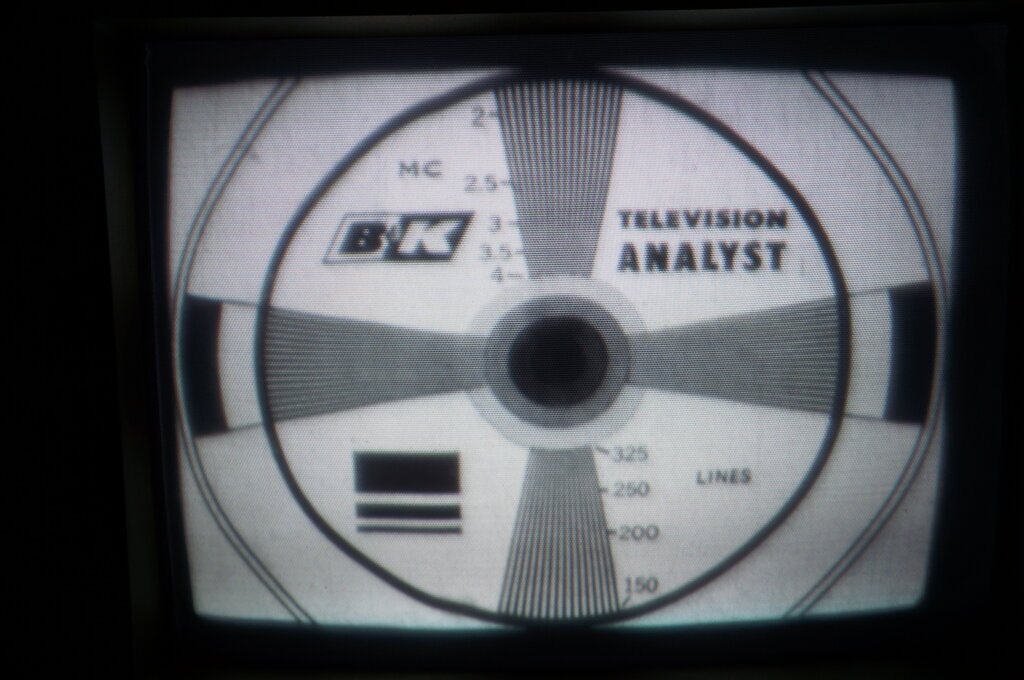
Image as seen on a Philips 1084S monitor.
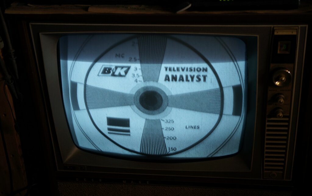
Image on an AWA D65 TV set. The RF modulator is tuned to Ch. 0.
The dark band is of course due to camera shutter speed and short phosphor
persistence on the CRT.
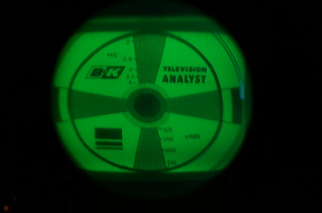
On the 5BP1
TV set, the image looks like this.
One More Fault!
After running the 1076 all day, it seemed
quite reliable. The dial lamp failed during this test run, but was easily
replaced. A few days later there was severe vertical jitter. This was strange
since there's no vertical oscillator as such.
Looking at the video waveform showed an
absence of sync pulses. Because it was easy to do, I simply tried another
12AU7, and that fixed it. Testing the original on the AVO valve tester
revealed that the sync phase splitter triode was completely inoperative.
This particular 1076-ES has been well used.
The PCB's were coated with grime which was gradually cleaned off with metho
as various parts were replaced. The grub screw for one of the knobs had
a stripped thread. This was fixed by using a slightly larger grub screw.
A point of note is the original pots have a fluted plastic shaft, which
is of slightly smaller diameter than the 1/4" diameter the knobs are designed
for. I used a piece of aluminium shim to build up the diameter and get
a better fit for the video gain knob. If this pot gets replaced, the shim
won't be needed.
The row of sockets along the bottom of
the front panel are designed to take a small diameter pin plug. Unfortunately,
the leads and plugs that came with this instrument must have gone missing
at some time because all the of the sockets have been forced with a larger
diameter plug. However, I found that a 3mm banana plug makes a good fit
into the damaged sockets.
The RF output and shorted turns tester
both use an ordinary 'microphone' connector, so a lead was made up for
this.
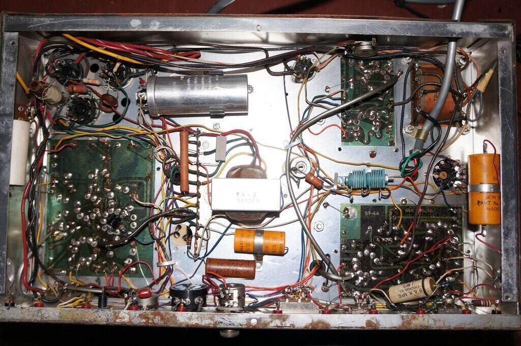
Under the chassis.
This one is in better cosmetic condition.
Around the early 2000's a work colleague who was once a TV technician gave me another 1076-ES. This one was a lot cleaner and in better cosmetic condition, and included were the test leads, extra slides, the instruction manual, and some notes from AWA about the Australian version. A nice inclusion was the neon high voltage tester still on the front panel.
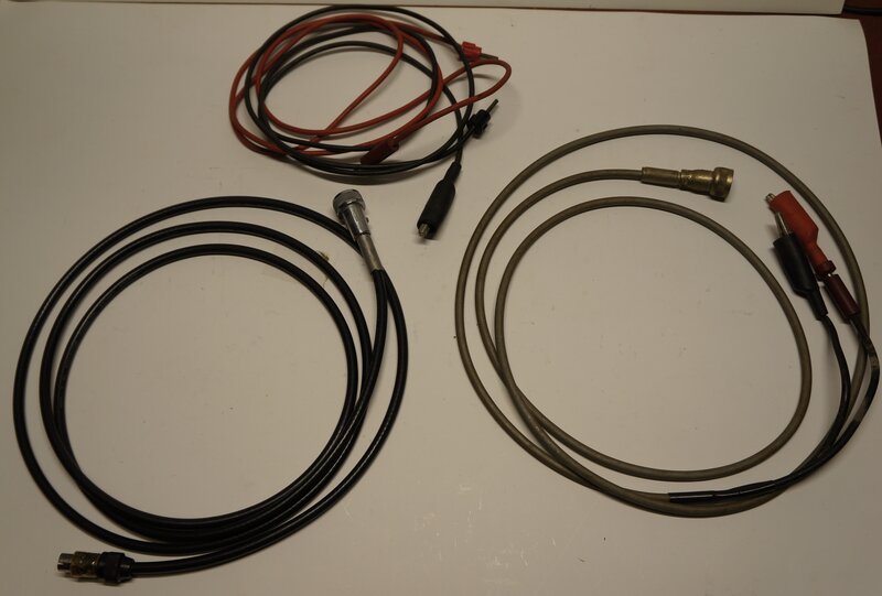
Test leads. At left is my original RF lead, at right is the genuine
RF lead that came with the second unit, and at the top are the test leads.
Getting this to work was a lot easier.
Back when I first got it, I replaced the likely paper capacitors and also
the filter electrolytics. Some of the resistors had already been replaced
with 1960's era types locally available.
Fast forward to 2021, and I didn't really
have to do any more to it. I noticed that all the valves are original,
except for the 6CA4 which had been replaced with an Australian made Philips
type. Two electrolytics on the audio board had also been replaced with
local Philips types.
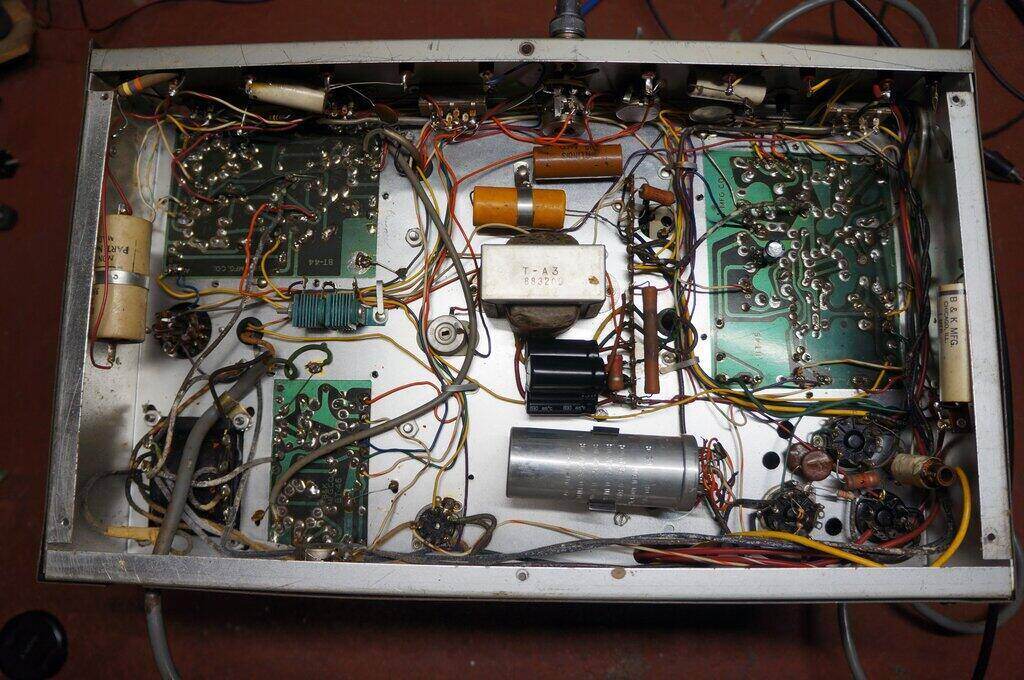
Under the chassis of the second 1076. This has more of the original
components.
After a day of running, the dial lamp in
this one also failed. A very strange coincidence. The way the dial lamps
are constructed in these, unless the bulb used has a round envelope, the
filament is not in line with the bezel. As fitted, both of my 1076's had
No. 47 bulbs which are of tubular construction. The filament is not in
line with the bezel and it's only reflected light that was visible. I actually
found a 12V 2.2W bulb as used in old cars for dashboard lights to be a
good substitute. The filament shines through the bezel, and the brightness
at the lower voltage is quite sufficient. Furthermore, it's unlikely to
burn out in my lifetime.
The mains flex is starting to harden and
should be replaced soon. Upon closer examination of the test leads, it
was noticed that the red and black pin plugs had been replaced by locally
made Jabel equivalents. Unfortunately, these do not fit properly being
too wide. Fortunately, they had not been forced into the sockets to the
point of damaging them.
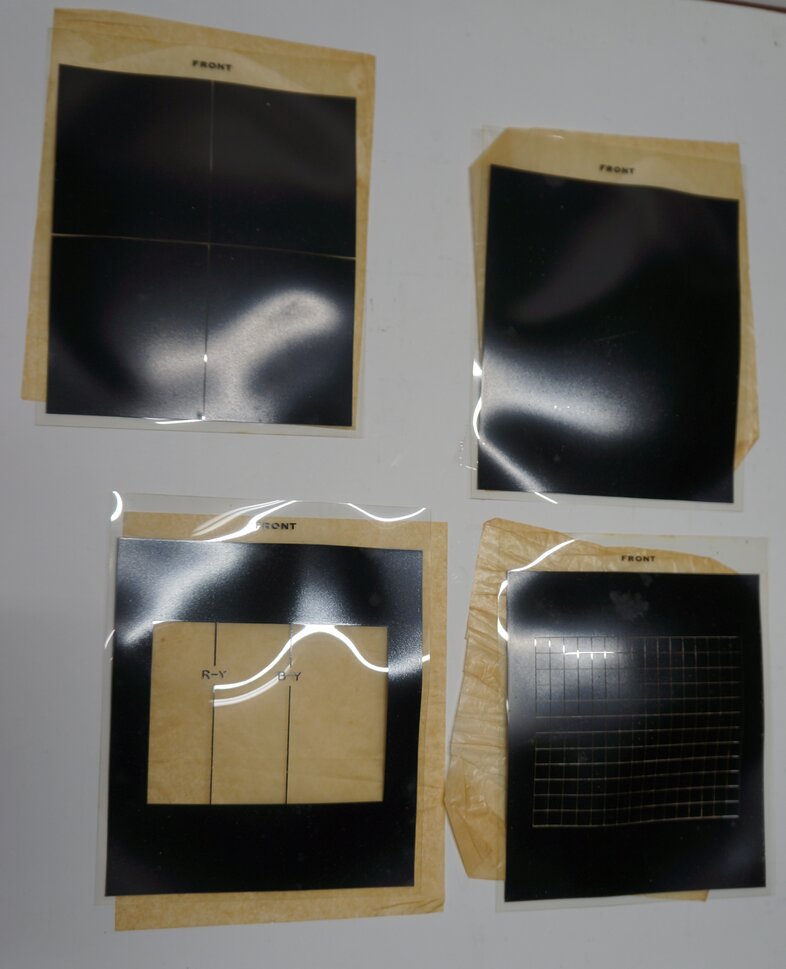
Extra slides for colour TV adjustment. The top right slide provides
a dot pattern.
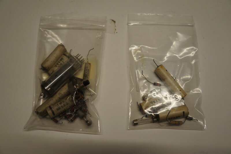
Parts replaced in both units.
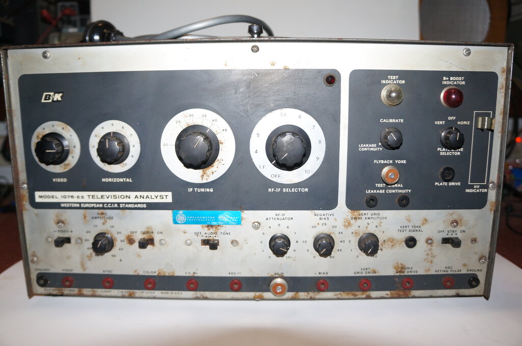
Note the Australian channels on the RF-IF selector switch.
As mentioned previously, a locally made
dial label has been used to cover the original for the channel frequencies.
A note supplied by AWA talks about the RF output frequencies:
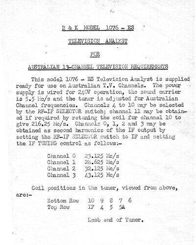
It is strange that they suggest receiving Ch. 0 on a harmonic, when the IF output is tunable up to Ch. 0's fundamental frequency. The output from the RF oscillator is certainly rich in harmonics, as seen on a spectrum analyser, and it's possible to receive some channels using different channel numbers to those designated on the output switch. There is an unmarked channel between 5 and 5A on the switch, but this is not of any normal TV channel frequency.