Of all the projects that appeared in RTV&H,
the 5" TV set would have to be my favourite. Although it is now 2016, my
experiences with this project go back to 1984.
Having successfully completed their 17"
design from May 1957, using a 21" CRT, my thoughts turned to the 5" set.
I'd first seen it browsing through old RTV&H issues in the Macquarie
University library, and I had seen 5BP1 tubes for sale at Deitch Bros.
disposals store in Sydney.
Armed with lots of enthusiasm, I bought
a non descript chassis from ACE Radio in Marrickville; one of the surviving
old time radio parts/disposals stores. I also bought a VCR139 CRT at the
time, thinking I'd use this instead of a 5BP1. The VCR139 is a 3" CRT of
English design. Initially, my plan was essentially to make up a video monitor
based on the RTV&H circuit, and feed video signal in from a VCR. Alas,
I'd taken too much liberty in circuit changes and was unsuccessful - I
had become overconfident. Now, I was forced to think about things and make
a more sensible approach. This time I purchased a 5BP1 for $2.00, and duplicated
the circuit more closely. Essentially, I used 12AU7's instead of 6SN7's
as these were, at the time, a good deal easier to get.
This time I was successful, and I can
remember the 5BP1 on my bedroom floor displaying its first pictures, with
video coming from my Grundig 2x4 VCR. With that success, I started thinking
about adding a tuner and IF strip so I could see off air pictures directly.
There was enough room on the chassis for the extra parts, so off to ACE
Radio again, this time to get some coil formers to wind the IF transformers,
and a tuner, which happened to be a Matsushita ENR5758, which I was familiar
with as my 12" Thorn portable also used this tuner. I made up an adaptor
so I could also plug in the VCR139A, which also worked very well.
With a subchassis made up, coils wound
and installed, and the tuner connected, I went in search of signals. I
had no test instruments except for a multimeter and audio oscillator, so
alignmment was by trial and error. Eventually, the image of the Channel
0 (SBS) newsreader appeared in a blurry smeared outline on the front of
the VCR139A. Further tweaking produced a watchable picture. I soon learned
that the way to align it was on the Ch. 0 test pattern, aiming for greatest
bandwidth before highest gain. I subsequently purchased the entire remaining
stock of 5BP1 tubes from Deitch Bros.
And so this became my bedside set, and
has been ever since. In late 1985 I rebuilt the set into a 5" CRO cabinet,
also purchased from ACE Radio. This CRO cabinet was one specified for all
the RTV&H CRO projects that used a 5BP1. Then in the late 1990's I
rebuilt the IF subchassis and aligned it properly. This set can be seen
at https://www.flickr.com/photos/13469158@N05/albums/72157627745067098
To the present time, and for a long while
I had been thinking about doing a more accurate replica of the RTV&H
design. It has a certain artistic charm about it, with all the octal valves,
and the 5BP1 sitting high up and in the open. Now, considerably more experienced,
and having more skills, I figured it wouldn't take much effort to get going.
And in 2015, I commenced construction.
At this point, it's probably best to start
by looking at the 5BP1, as this is really the heart of the set.
RCA first announced the 1802-P1 in November 1938, along with the 1802-P4. Both tubes are identical except for phosphor. The P1 being medium persistence green, and the P4 being medium persistence white. The 1802-P4 was used in two of the first RCA television sets released in time for the New York World's Fair in 1939. These were models TT5 and TRK5. The 1802-P4 became the 5BP4 under the RMA numbering system. Other manufacturers also used the 1802-P4, and some such as Meissner with their 10-1153 television kit, offered the option of the 1802-P1 with its sharper picture. Some details of these sets can be seen here.
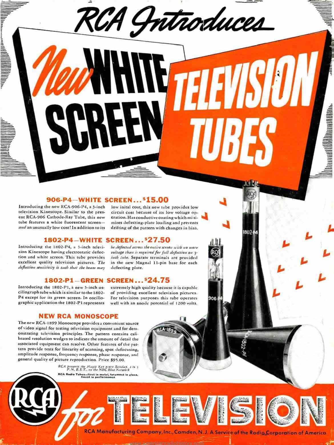
This was one of the 1939 advertisements announcing the introduction
of the 1802 cathode ray tubes.
From RCA's "Ham Tips", December 1938.
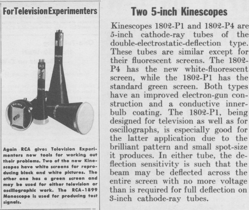
Note the statement above; "The 1802-P1, being designed for television...".
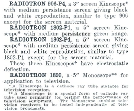
From AWV Radiotronics No. 93 (12th Dec. 1938). Note the term "Kinescope", and,"...suitable for television reception".
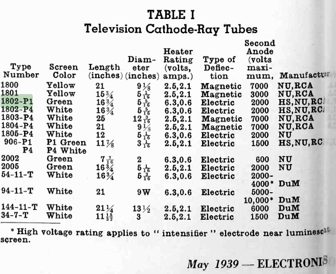
Television CRT's available in the U.S. in 1939.
In the above table, we see again the 1802-P1's television origins. Note the 1805. This is a physically shorter, but electrically identical CRT, developed by National Union. It is plug in compatible with the 1802. It is available with a white screen as the 1805-P4 (5AP4), or as the green screen version, 1805-P1 (5AP1).
Why Green?
To the modern television viewer, the concept
of a green picture might appear strange. It should be pointed out that
monochrome television has not always been white. Indeed, mechanical television
using Nipkow disc receivers invariably used a neon lamp as the light source,
and thus the picture was orange.
The first generation of cathode ray tubes
had green phosphor (willemite) for their fluorescent screens. This was
efficient because most of the light was concentrated in the visible spectrum,
and the human eye is most sensitive to green. The only known white phosphor
at the time also emitted light in the UV spectrum, and so was less efficient.
However, the viewing public wanted white
pictures, being used to photographs and printed material of that colour.
In the mid 1930's it was found that by mixing two or more phosphors that
white could be obtained, with the light concentrated in the visible spectrum,
and so the first generation of white screen picture tubes appeared. Nevertheless,
the green phosphor is still the most efficient and provides the sharpest
picture, which is why it was preferred for oscillographic displays and
higher quality television use.
The 1802 tube is very easy to drive. With a low deflection angle of 22 degrees, and an EHT supply of 2000V, ordinary triode valves and normal B+ supply voltages make for simple deflection circuitry. The picture is bright enough be viewed in ordinary room lighting provided the light is not shining directly on the screen. In practice, it is not necessary to run the tube with the full 2000V, and note the above advertisement claiming good TV pictures with only 1200V.
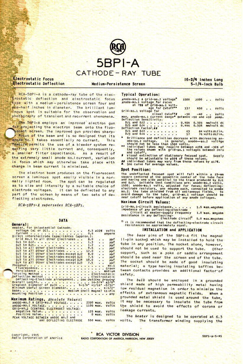
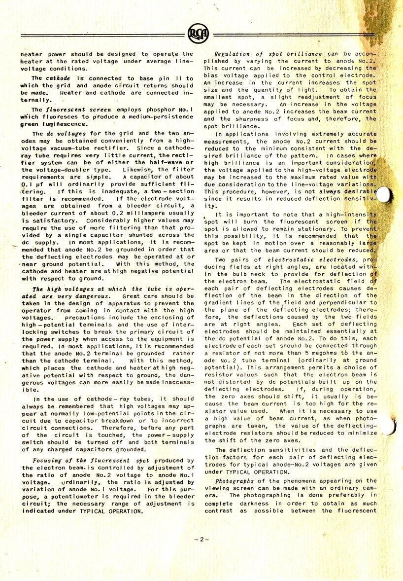
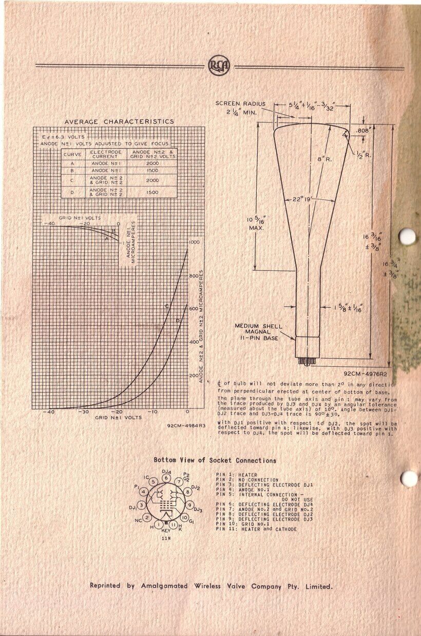
RCA data from 1945.
In Australia, the 1802-P1 / 5BP1 made its appearance in the disposals stores post war, and AWV were also trying to offload their war production tubes cheaply. They became popular for home made oscilloscopes, and Radio & Hobbies described a number of such circuits, with the last being in June 1960. As the 5BP4 had minimal application in military equipment (I am only aware of one oscilloscope model), it is very rare here, and I have not seen any examples. A very similar tube is the 1805-P1 / 5AP1. This is plug in compatible and has the same size screen, but is somewhat shorter. It too was used in some pre-war televisions. Apparently the 1805 was a National Union improvement on the 1802. I have a couple of examples of this tube and find them to perform the same as the 1802.
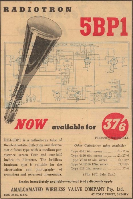
With televison not actually starting until 1956, this advertisement
from 1947 only made mention of the oscillographic qualities of the 5BP1.
Changing Fashions.
Electrostatic tubes were common in pre-war
TV sets, but post-war they were obsolete, except for small table and portable
sets in the U.S., being sold up until about 1949. By the time television
came to Australia in 1956, they were nowhere to be seen. Electrostatic
picture tubes have a number of advantages. Firstly, no special coils are
required for deflection, and neither are any matching transformers. These
by their nature are costly and specialised components. And, as any TV serviceman
will tell you, they can be troublesome parts. Electrostatic deflection
only requires simple resistance coupled amplifiers to drive the deflection
plates. Apart from simpler circuitry, no special components are required.
In the modern day where wound components for electromagnetically deflected
tubes are no longer made, this is an advantage for the vintage TV enthusiast.
Another advantage of electrostatically
deflected tubes is that they are immune to ion burn. This is because the
ions are deflected equally with the electrons. Thus, there is no need to
have specially shaped guns with ion trap magnets, or aluminised screens.
Then there is the fact that simple resistance coupled amplifiers require
only a few milliamps of current. Contrast this to the typical 100mA of
an electromagnetic line deflection stage.
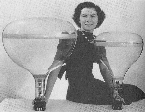
These DuMont 20AP4 and 14AP4 CRT's were the largest electrostatic
tubes used in domestic TV sets. It appears these may have been based on
a Cossor design. The English war time CRT, VCR131, looks suspiciously similar
to these, with similar appearance and what appears to be the same base.
However, because of the practical difficulties
of large deflection angles, electrostatic tubes tend to have a long neck,
as compared to an electromagnetic tube of the same screen size. This means
a deep cabinet if the tube is mounted horizontally for direct viewing.
While the long length of electrostatic tubes suit vertical mounting very
well, this requires a mirror in the lid style of cabinet. The largest electrostatically
deflected set made commerically was a 20" DuMont model. It was direct view
and thus had a very large and deep cabinet.
Fashions started to dictate that TV cabinets
should to be slim and unobtrusive, with direct viewing, and so deflection
angles increased over the years. Electrostatic deflection with its long
low angle tubes would not suit this trend. By the end of cathode ray tube
TV production, angles were up to 114 degrees. Some sets were so absurdly
slim that concrete blocks had to be secured inside the cabinet base to
prevent them toppling forward.
Television Starts in Australia &
the Era of "Disposals" Television Sets.
Test transmissions had started in Sydney
and Melbourne during 1956, and sets were horrendously expensive; about
a fifth of the price of a car. For the electronics enthusiast, parts to
make a set along the lines of commerical designs were just not available.
So, attention was drawn to disposals cathode ray tubes like the 5BP1 and
VCR97, and other parts that could be pressed into service to make a TV
set.
In December 1956, an article appeared
in Radio, Television & Hobbies describing a 5" television set. It had
been built up by Gil Miles, and as I discovered recently, the circuit is
based on a design appearing in the U.S. magazine, Radio News, for August
1947. Gil's design used the video, sync, deflection, and picture tube circuit
from the Radio News article, but the IF was designed locally and a commercially
made tuner used.
Apart from the front end of the set, the
design was very 1939-ish in design. Octal twin triodes for deflection,
a diode sync clipper, a 6V6 video amplifier, and of course the 5BP1 tube,
hadn't changed from the pre-war era.
The article was not a full on project
description, but more of a guide for experimenters. It was up to the constructor
as to how they built it; the suggestion being that it was built on a chassis
from disposals gear and used a tuner adapted from an ASV (Air to Surface
Vessel) receiver. Not keen on a mains transformer derived EHT supply which
the prototype used, because of its danger, RTV&H presented an
RF power supply in the January 1957 issue.
A five channel tuner was then described
in February 1957. After that, RTV&H was somewhat distracted by their
17" TV set, which appeared in the May issue presented by Neville Williams.
This was of conventional design using specialised parts, which were now
becoming available. Nothing more appeared on the 5" set until September.
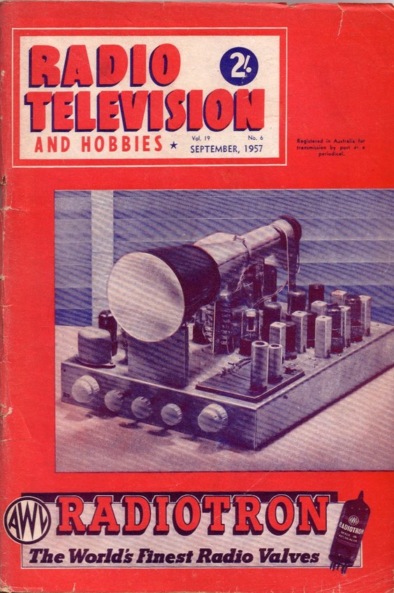
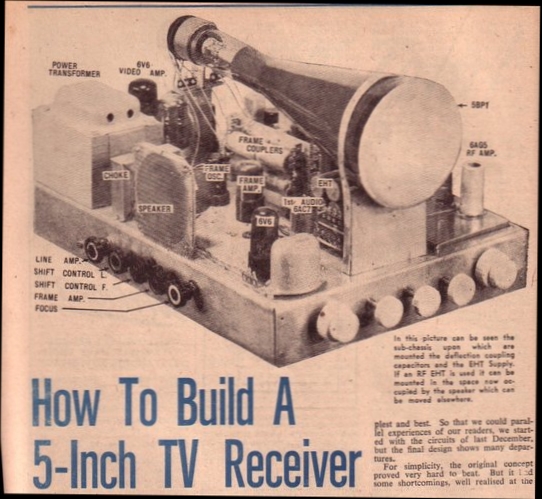
The cover picture shows the set not quite in its final form. Note
the 6H6 EHT circuit has not been mounted under the 5BP1 yet, and that the
rear mounting bracket for the 5BP1 differs to that shown in the subsequent
photos. One could assume that the RF power supply was in use at this stage
of development.
In this issue, John Moyle presented a full constructional article based on the December 1956 design. There were a number of changes to the circuit, and a chassis layout was provided. Additionally, the EHT power supply and tuner had been dealt with.
Subsequent issues dealt with an in depth article on building the IF strip, some minor improvements to the TV circuit itself, and discussions about alternative picture tubes. Lastly, the set was modified to take a VCR97 tube. The last electrostatic TV set articles appeared in August and September 1958, where the idea was to build up a full scale TV set along commercial lines, but to use a VCR97or 5BP1 to save cost until such time as the 17" or 21" picture tube could be afforded.
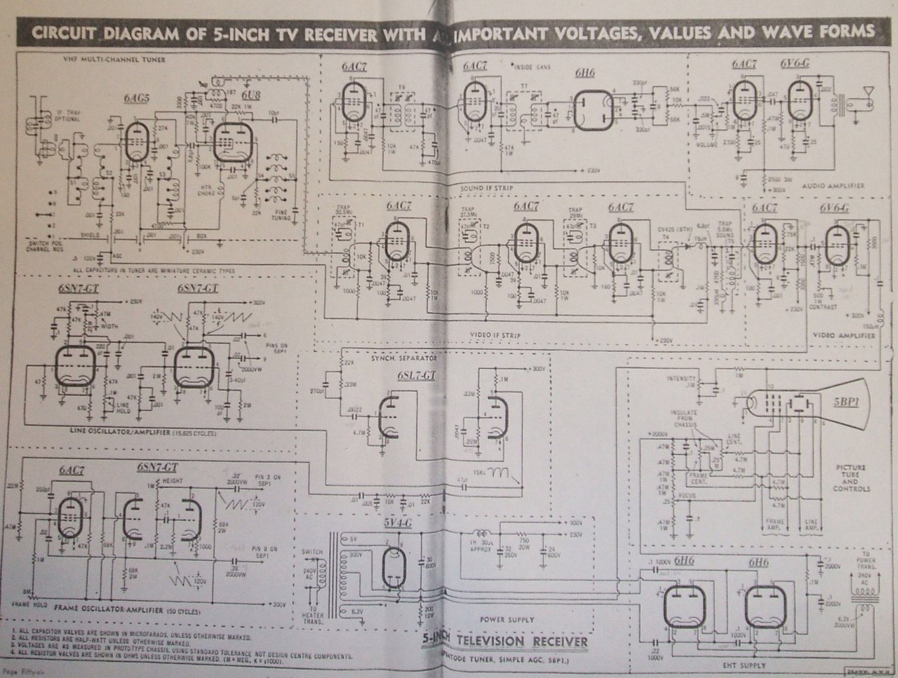
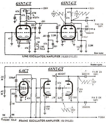
Circuit of the September 1957 5" TV Receiver.
Changes to the December 1956 Design.
1. Tuner.
This was electrically outdated in design
to start with because of the pentode RF amplifier (6AG5). Pentodes produce
more noise than do triodes. By the time TV came to Australia in 1956, twin
triode cascode RF amplifiers were standard, using valves like 6CW7 and
6BQ7. However, the approach taken was justified in that it used a 'disposals'
type valve and was likely to be easier to get going. The channel selection
arrangement takes the incremental approach with the coils mounted on Oak
switch wafers. They were forced to use a true television valve, 6U8, for
the mixer oscillator. For the sake of simplicity, only five channels were
included. At the time, only Sydney and Melbourne had TV and it seemed that
the existing channels 2,7, and 9 would be the status quo for a long time.
An article on replacing the RF amplifier with a 6BQ7 in a cascode circuit
was presented some time later.
2. Video and Sound IF strip.
This was part of the original Gil Miles
design, and was quite conventional. Specifications were included for winding
one's own coils. The performance of the video IF amplifier was up to commercial
standards, and it appears that some of the commercially made IF strips
for home constructors, made by establishments such as Aegis and Q-Plus,
may have been based on this design. The 6AC7/1852 was apparently quite
prolific in disposals gear. Being a pre-war video IF amplifier valve, it
was quite appropriate for this circuit. The nine pin miniature 6BX6/EF80
is a modern substitute.
The sound IF amplifier is also completely
conventional. By this time, the intercarrier method was standard, and this
circuit follows suit. One stage of sound IF amplification at 5.5Mc/s feeds
a limiter stage, and then a ratio detector.
3. AGC.
Probably because it had been used in the
May 1957 17" set, the 5" set also incorporates simple AGC. A convenient
feature of the negative modulation system is that the detected video is
negative going, and by filtering, it can be used to provide a negative
AGC voltage. It does have some limitations; in particular producing limited
control voltage (the AGC voltage can never be higher than the detected
video peak voltage, which may not be enough to throttle back the front
end valves). Also, the AGC voltage is dependent somewhat on the actual
video modulation, resulting in voltage changes with the scene content.
In practice, the scheme works well enough provided the input signal to
the tuner is not unduly high, and that the video stages are not direct
coupled to the picture tube. RTV&H was a great fan of simple AGC, using
it in most of their TV designs. A few commercially made sets used it, but
it was nowhere to be seen in any Australian designed TV set beyond about
1958.
The December 1956 circuit did not include
any gain control for the IF amplifier, automatic or otherwise. This would
have restricted performance somewhat with overloading on strong signals,
unless externally attenuated.
4. Audio amplifier.
This is completelty conventional and little
needs to be said. It is a simple triode pentode affair using a common circuit.
Unfortunately, no thought was given to negative feedback, but then at the
time few designs used it. Again, looking for places to put 6AC7's, one
has been used here, this time for the audio voltage amplifier. It is wired
as a triode as the gain required is not high. The 6V6 had been the standard
octal output valve in Australian radios for some time, and is also used
here.
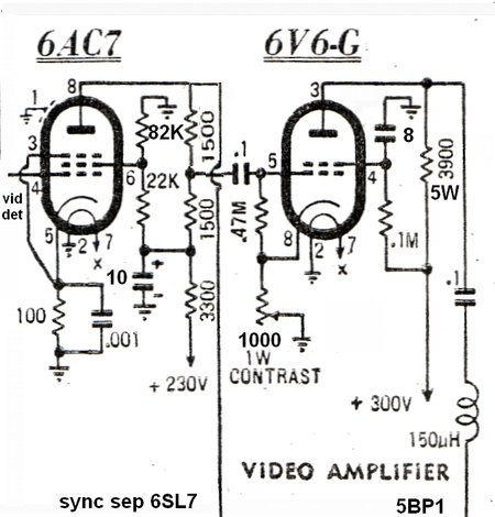
5. Video amplifier.
For this section, the December 1956 article
shows what is really the original Radio News circuit from 1947, based on
pre-war design. Here, the video detector feeds a 6V6 which is then direct
coupled to the 5BP1 grid. Because the 6V6 is operated with grid leak bias,
it means the DC level at the plate is determined by the sync pulse amplitude,
and thus so is the 5BP1 grid. As a result, we have DC restoration.
In the 1957 updated circuit, things have
been changed somewhat. A 6V6 is not a particularly high gain valve, compared
to later "proper" video amplifier pentodes. So, a 6AC7 amplifier now precedes
it. Because of the extra stage inverting the signal, it meant that the
video detector diode could be reversed and provide a negative going output
in the usual way - hence the ease of now applying AGC. The circuit is typical
of post war video amplifier design in the U.S. when it was still fashionable
to grid drive picture tubes.
A contrast control is included in the
6V6 cathode by means of a cathode rheostat, which provides an adjustable
amount of negative feedback, and thus gain control.
Because of the contrast control having
an influence over the 6V6 plate voltage, and that the 5BP1 has the cathode
internally connected to one side of the heater which is earthed, the 6V6
is now AC coupled to the 5BP1. In the original circuit, the 5BP1 heater
was operated off a floating winding on the power transformer, to which
the brightness control was connected. There were arguments aplenty with
the pros and cons of AC vs. DC coupling in the day. In practice, AC coupling
works well enough in this application, and simplifies set operation - the
contrast and brightness controls operate independently, and the brightness
is not dependent on signal strength. It also eases the load on the EHT
regulation requirements as the average brightness (and thus beam current)
remains the same regardless of scene content.
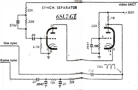
6. Sync separator.
The Radio News circuit had been used for
the December 1956 design. This used a diode clipper to extract the sync
pulses from the video, and a 6SN7 as a two stage amplifier operating with
no initial bias. In the 1957 circuit this was changed to a more conventional
grid leak sync separator circuit using a 6SL7, which also had the advantage
of extra gain from the 6AC7 first video amplifier to drive it. Somewhat
unusually, the 6SL7 is operated in cascode; the reason being that the timebases
in this set require negative going sync pulses.
7. Line timebase.
The Radio News/ Dec 56 RTV&H circuit
was retained here, but with a minor modification to improve linearity.
It uses a 6SN7 multivibrator, with another 6SN7 as a push pull output.
The phase inverting stage of the output received its input from a resistive
divider in the Radio News circuit, but Gil Miles used a simpler capacitive
divider instead. By adjusting the coupling capacitor, both 6SN7 plates
will provide the same sawtooth voltage amplitude.
8. Frame timebase.
Originally this used a 6SN7 multivibrator
driving a push pull 6SN7 output stage and the circuit was also based on
the Radio News design. However, it was found the linearity was difficult
to make perfect, and so a Miller-transitron circuit was used instead. This
was based on the "High Quality CRO Timebase" article described in
September 1956 by Maurice Findlay. Essentially, with positive feedback
between plate and screen, the 6AC7 oscillates, and with the Miller effect,
provides an extremely linear sawtooth. This feeds a 6SN7, one half being
used as a cathode follower to provide a negative going sawtooth, and the
other half as in inverter, providing the positive sawtooth. Thus, push
pull operation is achieved.
9. Picture tube.
A conventional resistive divider incorporating
shift and focus controls provides the necessary voltages for the 5BP1.
The EHT required is 2000V. Most of the current, about 1mA, is consumed
by the voltage divider.
10. EHT supply.
It was not stated what they were, but
in the September 57 article, it was said that the January 1957 RF power
supply "has its own problems". Evidently, someone remembered the "Westeht"
Westinghouse diode/capacitor voltage mutliplier circuit used in some British
sets and this was adapted for the 5" set, but using 6H6 valves instead
of selenium rectifiers. It's an adaptation of the Cockroft-Walton voltage
multiplier circuit. The choice of 6H6's and a common heater winding for
them in this 5" set was not a good one, because the heater cathode insulation
is severely stressed. Also is the fact that the current through some of
the 6H6 diodes would be in excess of their ratings. Nevertheless, RTV&H
reported good reliability, and conceded that 6H6's were cheap enough not
to worry about if they did fail!
11. Power supply.
A commercially made TV power transformer
and choke was used in John Moyle's set, but the article hinted that anything
likely looking that the constructor might have should be tried. Back bias
was used to obtain negative voltage for the 5BP1 grid. Unfortunately, this
subtracts from the B+, which should be kept high to obtain sufficient deflection.
The recitifer was a 5V4, probably because it was cheaper than a 5AS4. It
would also have the advantage of less voltage drop, compensating for some
degree that which is lost across the back bias resistor.
My Construction of the September
1957 5" TV set.
For my third build of this set, I wanted
this one to replicate John Moyle's design as accurately as I could within
reason.
I had an identical power transformer,
so this was cleaned up and repainted. For the IF strip, I decided against
winding up my own coils partly due to not having any coil formers, and
I've already been there and done that with my previous version. Also, 32
years later I've accumulated a lot more TV parts - including scrap chasses
that could provide an IF strip. Having a look around, I found my scrap
Stromberg Carlson 821 chassis had the video and sound IF strips already
assembled on a subchassis. Perfect. They could be removed easily, tidied
up, and modified slightly to suit the 5" set.
The tuner was to be the same Matsushita unit I bought for my original set in 1984. I had replaced it with a Sharp solid state set of VHF/UHF tuners during the rebuild in 1985 because I wanted UHF reception. Now that there's no analog off air signals, UHF reception was not required in my new set.
I also gathered up some 2000V capacitors for the EHT supply and deflection plate coupling circuits. My luck was still winning, because I also found I had the exact same knobs for the presets, and the same ones for the front panel controls, althought black instead of white. I had a bit of search for a concentric dual pot with switch for the volume and brightness controls, and eventually found one that would suit the Aegis knobs. While I could have mounted all the controls on the chassis front, I decided to keep to the design and use extension shafts where appropriate, and have the pots physically close to the circuits they were controlling.
The EHT supply caused some thought. 6H6's were out of the question as I don't have enough to use when they might have a short life. 6AL5's are an alternative of course, being electrically the same. However, a quick test showed that there was flashover if I tried using them in the multiplier circuit. I had used 1N4007 silicon diodes instead for my previous sets with complete reliability, but I felt that the solid state approach would be out of place in a period correct set. Lurking in my parts cupboard for the last 30 odd years were a couple of Aegis M23 RF EHT coils which suited the January 1957 RF power supply. Now was the time to try the RF approach - being much more period appropriated than 1N4007's! If things didn't work out, I'd go down the solid state route again.
I went through my valve collection, picked out the first 5BP1, found the necessary 6AC7's, 6SN7's and so on. I particularly wanted G style 6V6's. For the rectifier, I decided on a 5AS4 as I've got a good deal more of those than 5V4's, and with the RF power supply I would require the higher current. Fortunately, I had some G style 5AS4's so one of those was set aside. I had recently acquired what looked and tested like a 6J5, in G style, and this would be the audio voltage amplifier.
The dimensions of the chassis and valve
socket locations were included in the article, and so in July 2015, I cut
and punched a 1.5mm thick aluminium chassis accordingly. Unfortunately,
the location and dimensions of the various brackets, controls, etc. had
not been given, so I had to scale these from the photos, and this slowed
things down a little.
Insulated mounts for the shift controls
were made out of Lexan, as they need to be floating because of 2KV applied
to them. I have to say the insulation of modern pots is surprisingly good,
because for my 1984 version of the set, these pots were earthed. Only occasionally
was there a flashover. For the 1985 rebuild, their mounting bracket was
on a wooden block. Extension shafts were made from aluminium rod and plastic
couplings turned down on a lathe.
Brackets were then made up for the picture
tube mounting, and the panel for the deflection plate coupling capacitors.
Here, I added Lexan panels to prevent accidental touching of the
2000V connections.
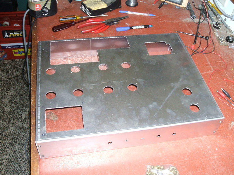
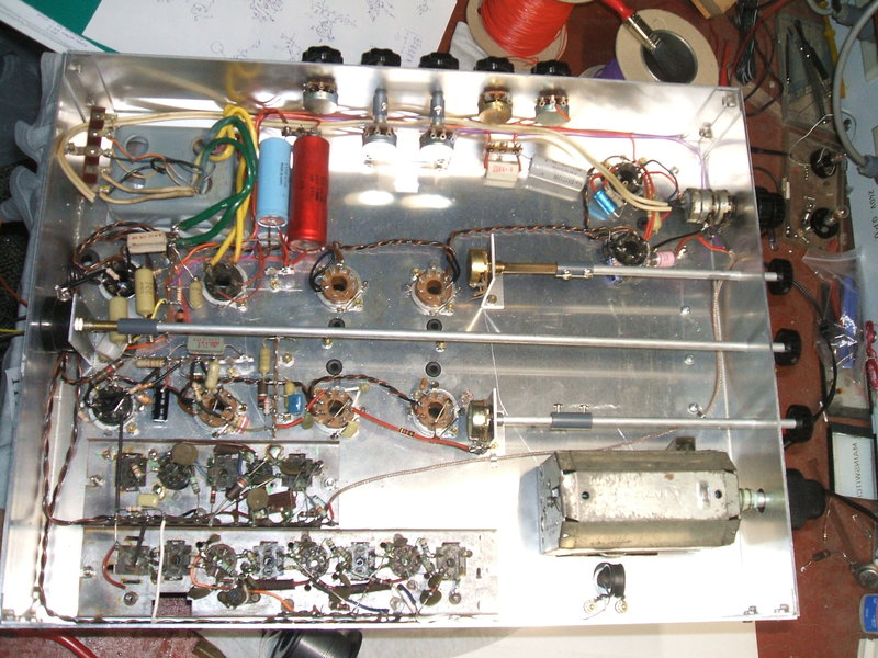
Chassis bent up and punched ready for parts to be mounted.
By the 2015 Xmas holidays, with parts gathered and the chassis complete except for minor holes, it was ready to commence installing parts. The valve sockets were mounted first and then the tuner.
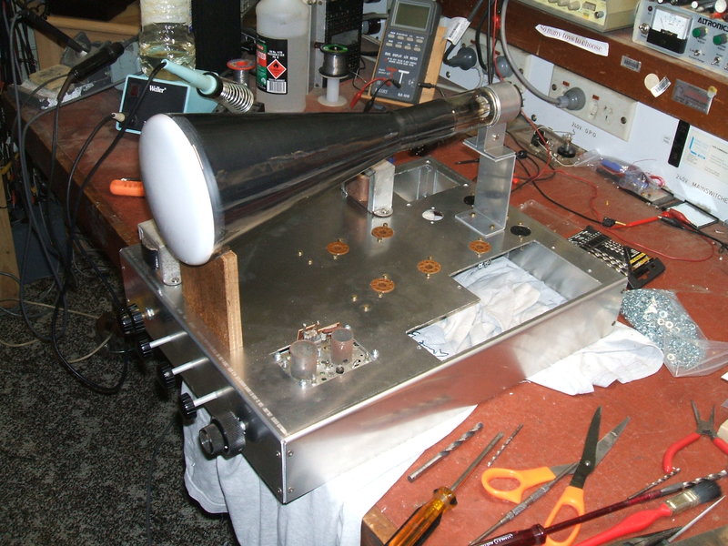
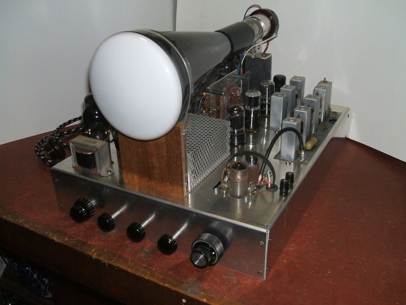
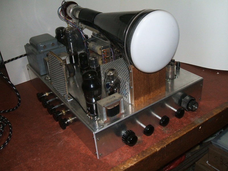
The first glimpse of what the set will look like. The 5BP1 is a
work of art in itself so is best clearly displayed like this.
The front of the 5BP1 is supported by a piece of 10mm thick plywood. I shaped it for a close round fit to the tube and glued a rubber strip to it for the tube to sit in. A strap would be added to secure it.
Tuner.
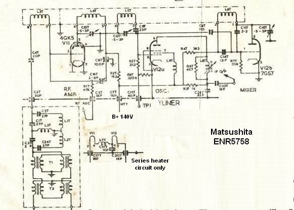
The 5" set uses the parallel heater version of this tuner with 6GK5
and 6GS7 valves.
The tuner I used is one made by Matsushita in the early 1970's. It was used by Thorn in their R and S series sets, and also of course, by National. It is licenced to Sarkes-Tarzian and uses a 13 channel turret. Design is conventional for the late 1960's, with a 6GK5 as a neutralised RF amplifier, followed by the pentode of a 6GS7 as the mixer, and the triode as local oscillator. This valve appears to be unique to Matsushita. Video IF output is 36.875Mc/s.
The tuner was purchased for the original 5" set I built in 1984, as at the time building the RTV&H Februrary 1957 tuner was completely impractical. Not having the correct knobs for the tuner, I discovered that a couple of knobs sold by Jaycar at the time fitted perfectly. The fine tuning knob is a large knob with the brass bushing removed and a hole drilled through it, while the channel knob is an ordinary 1/4" shaft type.
On further thought, I could have built a tuner this time round, and simplified it too - only needing channels 0 and 3, but it was for convenience and sentimental reasons I retained my original.
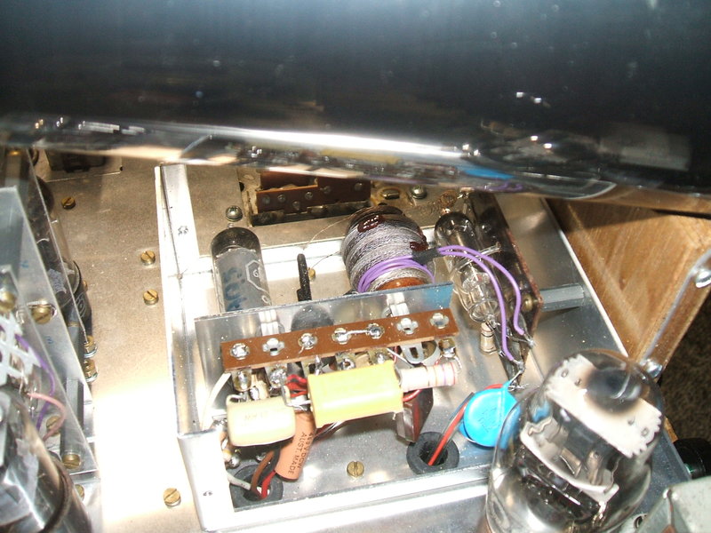
Vision and Sound IF Strip.
At this point, I turned to the IF strip
as this would be mounted next. But first it needed to be cleaned up. A
Scotchbrite pad and CRC did a good job of getting the pitting off the aluminium
coil cans and cleaning the grime off the chassis. The unecessary parts
and wiring were removed, and the paper AGC filter capacitor replaced with
a polyester type. All others were ceramic or electrolytic and so could
stay.
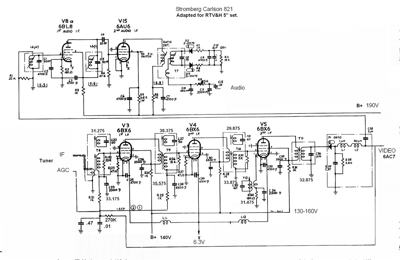
Circuit of the video and sound IF amplifiers, and AGC.
Having a prebuilt IF strip took a lot of
work out of building the set. I had constructed the IF strip for my first
version, so I can at least say I have done it once. The Stromberg Carlson
chassis was the perfect donor because the IF strips; sound and vision,
were on separate subchasses. They were also of such dimensions that would
fit perfectly into the 5" set chassis.
The IF strips were used as is, being in
fairly good condition. They basically needed a cosmetic clean up, and any
remaining paper capacitors replaced. All the resistors tested OK.
Several modifications were in order. Firstly,
the AGC. The Stromberg Carlson used gated AGC. Therefore all the gated
AGC components on the subchassis were removed, and the circuit modified
to use simple AGC. Essentially, the new AGC system consists of a 270K resistor
and .01 and .47uF capacitors. In the RTV&H design, the decoupling resistor
is 100K, but I found there was some tilt on the video waveform because
the time constant was not long enough with the .47uF filter capacitor.
I could have increased the capacitor value, but it was more convenient
to increase the resistor to 270K. The .01uF looks superflous on the circuit,
but is located at the other end of the chassis to the .47uF. It simply
removes any remaining RF. There is no AGC delay which means sensitivity
could be reduced with weak signals - the voltage created from the noise
reducing the gain, but in practice any signals in the present day will
be coming from RF modulators and not distant TV stations. As mentioned
before, the range of control is limited with sync crushing evident on very
strong signals. In this situation an external attenuator is required. In
practice however, this AGC system works well enough, and there were no
problems evident with the 1984 set receiving off air signals.
The sound IF is unaltered except that the 6BL8 triode is no longer used. It was part of the original AGC circuit. I had ideas of using it as a diode for a DC restorer circuit or a peak level AGC detector, but is unlikely I'll do so.
Because of the Matsushita's tuner IF being
36.875Mc/s instead of 36Mc/s, the IF strip was aligned by adding 875Kc/s
to each alignment frequency. One problem with the old 36Mc/s IF was interference
with channel 2. This is an irrelevant point now because there is no channel
2 to be received, but it was felt more correct to adapt the IF strip to
the tuner, rather than the other way round - it being easier to do so.
This IF strip is a very good performer,
particularly in regards to freedom from intercarrier buzz.
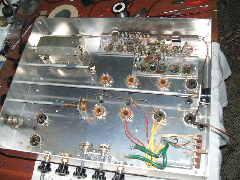
Most of the major chassis parts are now installed.
With the tuner, IF strips, and power transformer
now installed, the heater wiring was commenced. Rather than have high 50
cycle currents flowing through the chassis, I prefer to use a twisted pair
feed for the 6.3V supply to each valve socket, earthed only at one point.
However, in the case of the tuner and IF strip, the valve heaters are earthed
at the sockets so an exception has to be made here.
I spent a couple of afternoons on the
video, sync, and audio wiring.
Video Amplifiers.
Experience with my previous versions of
the set showed that the originally specified 500 ohm contrast pot did not
give sufficient range of adjustment, hence the 1000 ohms used here. Because
of preferred values, the 75K screen to earth resistor is now 82K, and the
6AC7 decoupling bypass is 10uF instead of 8uF. A modification that was
described in the subsequent issue has also been incorporated. That is to
double the 6AC7 plate load from 1500 to 3000 ohms to provide increased
drive to the sync separator. So that the 6V6 output stage receives the
same drive, its input is tapped from the original 1500 ohm point. The bandwidth
is quoted as being flat to 4Mc/s. It was also recommended that the .1uF
screen bypass for the 6V6 be increased to 8uF for better low frequency
response.
The 6V6 relies on the sync pulses to bias
it. With no video signal, bias for the 6V6 is therefore minimal. Under
these conditions, the screen and plate resistors limit the current to a
safe level.
For my first version of this set, I used
the pentode section of a 6DX8 instead of the 6AC7. The 82K screen resistor
was not used, and the plate load was a single 2.7K 1W resistor. This actually
worked very well, and had higher gain than the 6AC7 stage shown here. In
that set, the contrast pot was 5K.
Sync Separator.
Two changes were suggested by RTV&H. These were to increase the video coupling to .01uF and decrease the 220K to 100K for the second triode's grid voltage divider. This improved the low frequency response for the frame sync and improved the clipping level. My 1984 version used a 5751 (high spec 12AX7) instead of the 6SL7, and my 1985 rebuild uses a 12AT7. The 5751/12AX7 worked well with the high input as a result of using a 6DX8 first video amplifier, but with the 1985 version reverting to a 6AC7, the higher gain of a 12AT7 gave better results.
Audio Amplifier.
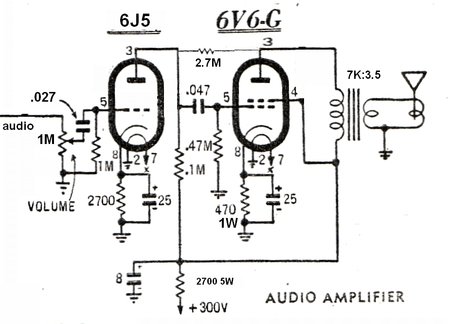
Because I had one to hand and it looked
more attractive, I used a 6J5-G triode instead of the triode connected
6AC7 for the audio voltage amplifier. Operating a pentode output stage
without any negative feedback does not impress me, so I included a 2.7M
shunt resistor to provide this function. The idea of using a plate bypass
to roll off the naturally rising frequency response instead is crude, in
my opinion.
I used the speaker transformer from the
Stromberg Carlson 821 chassis that also provided the IF strips. It has
a 7K primary, but this better suits the operating conditions of the 6V6
as used here. Note that the bias resistor is 470 ohms. This is a
carry over from the December 1956 circuit that used a 6K6. It is higher
than the usually specified 250 ohms, but in this application makes sense,
because with a 4" speaker with no baffling, there is no way that this stage
needs to provide 4W power output. The 6V6 will also last longer with the
lower cathode current. Minor alterations were that the 6J5 coupling capacitor
was changed to .027uF because it was what I had, and is non critical, and
the B+ decoupling resistor was changed to suit preferred values. The volume
pot value was dictated by the concentric dual pot, and is again non critical.
As per the RTV&H set, a Rola 4" speaker
was used mounted on the side of the chassis and protected by expanded mesh.
Despite pointing away from the viewer and not being baffled, the sound
quality is actually quite good. The particular speaker needed cone repairs
with contact cement. This is a good adhesive for the purpose because it
remains flexible.
Under chassis wiring half complete.
Next was to wire up the line and frame oscillators and output stages.
Timebases.
The line timebase remains unaltered except
for the use of preferred values; i.e. 2.2M instead of 2M, and the inclusion
of a .001uF in series with the trimmer capacitor feeding pin 4 of the output
triode.
This was done because of the posibility
of breakdown of the trimmer - something that did occur with my original
version of the set. That set used 12AU7's instead of 6SN7's, and when the
trimmer flashed over, the 12AU7 grid was damaged. The output coupling capacitor
value is not critical, and here I used .01uF instead of .02uF. This goes
back to my original set when all I could get were .01uF 3KV capacitors.
The frame timebase is largely unaltered,
but again preferred values have been used. One thing that appears to be
a mistake is the original circuit shows the frame hold pot as 500K rheostat
connected.
With my third build of the design, I have
proven that this does not give anything like the range of adjustment to
get 50c/s. It either needs to be a 5M pot, or connected as a voltage divider
as I have done here.
I wonder how many constructors ran into
this problem.
The output coupling capacitors are .1uF
instead of the quoted .22uF. RTV&H mentioned this was a misprint and
the capacitors were actually two .22uF 1KV in series (.11uF 2KV). Interestingly,
I had one of them break down soon after completing the set, despite being
a new old stock polyester type.
The output stage is interesting in that
the amplitude of the lower sawtooth remains constant and the height control
only affects the upper sawtooth. It certainly works and has excellent linearity.
The deflection plate pins have been swapped
around for both timebases. This is because I had mounted the 5BP1 180 degrees
out, and because of the wiring to the socket it was not convenient to simply
rotate the tube to show the picture the right way up. Because one set of
plates has to be further than the other from the cathode, it means there
is a difference in sensitivity. Therefore, the line plates should not be
swapped with the frame plates.
A problem with using old 6AC7's became
evident in this new set. Unfortunately, metal valves have a weakness with
the metal to glass seal, resulting in many becoming gassy over time. This
is evident in this set because of the long warm up time before the frame
oscillator frequency stabilises and locks. The video amplifier 6AC7 is
similarly affected because a similar amount of time is required (nearly
one minute) before full contrast is obtained. Both my previous versions
of the set used a 6BX6 (all glass) for the frame oscillator and this does
not occur.
Main Power Supply.
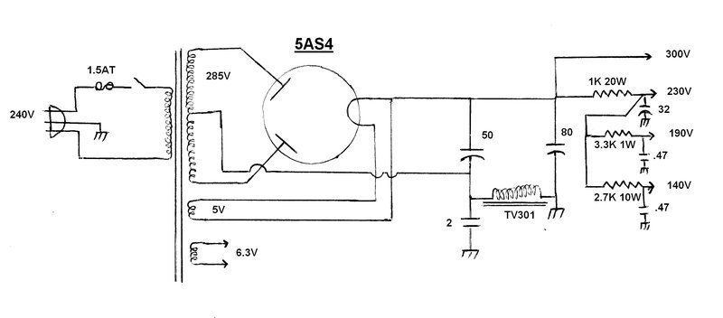
Now, we come to the main power supply.
One alteration was to provide the required voltages for the tuner and IF
strips. A departure in design was also made with regards to the filter
choke being placed in the negative return circuit, partly to obtain a source
of back bias as described later on. Once the set was finished and operating,
I resonated the choke with the 2uF. This dropped B+ ripple from 2Vp-p to
500mVp-p. The cost cutting design is evident in all the commercially made
sets that do not do this. There is about 15Vp-p across the choke/capacitor
circuit. The filter capacitor choice was governed by what I had available,
and is not ciritical.
Having seen what short circuits do to
power transformers, I included a 1.5A time delay fuse in the primary. The
transformer itself was given to me by an HRSA member. I have no idea what
set it came from, but it looked identical to that in John Moyle's set.
It still had the rectifier socket and mains tagstrip attached and these
were re-used.
My first version used solid state rectifiers
(1N5404 diodes), but the 1985 rebuild uses a 5V4. Both used resistive filtering
instead of a choke.
The last bit of under chassis wiring was for the picture tube:
Picture Tube.
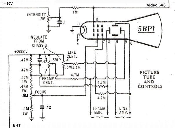
The changes here were to use 500K pots instead of 250K. I had used this value of pot in the previous sets because it was all I could get at the time, and with the advantage of slightly less loading on the EHT divider, had decided to do the same again. The resistor between the focus pot and earth had to be changed to 100K to restore correct focus range. Also, because I had them, .12uF was used instead of .1uF for the two capacitors. The Intenstity, or Brightness, pot was originally 100K, but because the dual concentric pot I had was 200K, that's what was used. As it's a simple voltage divider, the value is not critical. Note that the second anode of the 5BP1 is not actually connected directly to the EHT supply. It is about 200V less. An interesting experiment would be to replace the two 470K resistors that feed the second anode with a 1M pot, thus providing an astigmatism control to adjust for roundness of the spot.
Another couple of afternoons saw the wiring
essentially complete, with only the EHT supply to go before I could see
something on the screen of the 5BP1. And here I struck a bit of a set back.
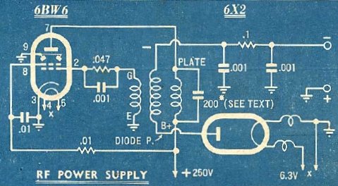
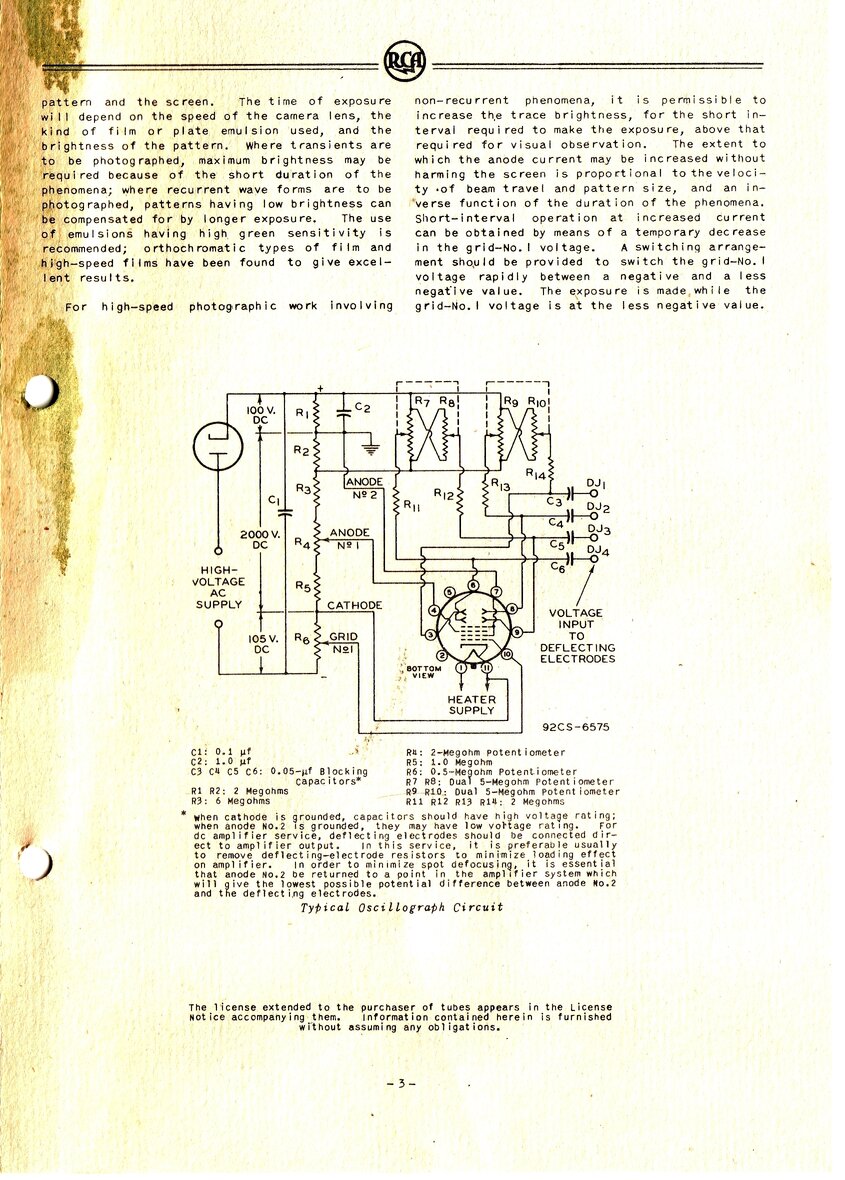
Circuit of the January 1957 EHT supply. The wiring here shows the
rectifier configured for negative output as used with most CRO's. 6BW6
is the 9 pin version of 6V6. Output adjustment is by the 200pF across the
plate winding.
The RTV&H article from January 1957
was followed, except I decided to use a 6CW5 for the oscillator valve instead
of a 6BW6. I thought the lower plate voltage of the 6CW5 would equate to
greater efficiency and higher output. By the way it was written, the article
implied there wasn't a reserve of output for this supply. The box was cut
and bent up with a small subchassis mounted to support the valve socket
and RF coil. The latter caused a lot of thought because it was rather fragile
with delicate Litz wire leads hanging off it. Ultimately, I decided the
best thing would be to use grommets in the sub chassis and feed the wires
through to the tagstrip and valve socket via rigid spaghetti tubing. I
would have preferred the coil to be constructed on a base with pins - it
would have been easier to deal with.
The next challenge was what to do about
a rectifier. RTV&H didn't seem too confident about an added heater
winding for the 6X2, instead recommending a suitably insulated mains transformer.
They seemed to think it was difficult to measure the heater voltage (at
1Mc/s), and that it might load the supply too much. I didn't like the mains
transformer idea for heating the 6X2 because it meant more magnetic radiation
to interfere with the 5BP1. Besides, commercially made sets with RF EHT
supplies use an added heater winding successfully. No, I'd persist with
the added winding.
For the rectifier, I considered common
valves like 1X2 and 1S2 but they don't have the current rating required.
1B3 does, but would be too big. So, I settled for a 6X2/EY51 as per the
original circuit.
The circuit is that of a simple tuned plate - tuned grid oscillator, with the output adjusted by tuning the plate winding towards or away from resonance. A trimmer capacitor is used for the purpose. A greater range of adjustment can be had by changing the screen grid voltage.
Results were disappointing. While one could
just get 2000V at 2mA, it required a B+ voltage of 350, and the current
was up around 50mA. This seemed terribly inefficient. And then I noticed
the RF coil primary getting rather hot. Maybe the 6CW5 having a low plate
voltage was the problem. So, I tried a 6M5. No better. I even tried it
triode connected with much the same results.
Things were just not tallying up here.
I knew very well from the commercially made sets I'd worked on that an
RF EHT supply should be a lot better than this. I was also bothered about
the vagueness of the RTV&H article, and felt it wasn't telling the
full story. The circuit was based on that described in the January 1946
issue of Radiotronics, No. 117(the AWV in-house magazine). I was able to
find a copy of that on the internet, and also quite a detailed article
from RCA on the subject. The more I read it, I had an idea what the problem
was. You see, if either the grid coil or plate coil is reversed the circuit
will still oscillate because the phase reversal still happens. The catch
is this phase reversal happens at another frequency, and not being the
resonant one, the supply works very inefficiently.
Thus alerted, I checked for the umpteenth
time, and sure enough I had the plate coil reversed. Once this was corrected
all was good. I made up a new sub chassis with a 7 pin socket and decided
to use a 6AQ5. (Had there been sufficient room I would have used a 6V6).
With a 2mA load, it was easy to get 2KV with a B+ of 250V at about 35mA.
There was no problem at all driving the 6X2 heater, with no loss of EHT
because of loading, and minimal increase in B+ current.
I actually suspect RTV&H fell into
the same trap because they quote 300V at nearly 50mA required to get 2000V
into a 500uA load (i.e. just the volt meter loading the supply), and they
mentioned the heat from the supply. I noticed also that they used something
besides the Aegis M23 transformer - the coil spacing is slightly different.
The Aegis coil follows the Radiotronics design.
Measuring the 6X2 Heater Voltage.
Now, how to measure the 6X2 heater voltage?
Well, it's operating at 1Mc/s (sine wave) so normally one would like to
use a CRO. Problem is there's 2000V superimposed on it. I wondered about
using an ordinary digital multimeter, but found it wouldn't respond properly.
Surprisingly, I found my AVO 8 MkV did however have a very good response
on the AC volts range. The question is what's it really reading?
To answer that, I used a sine wave function
generator operating at 1Mc/s to feed the CRO, and set it to 17.8V p-p,
which is 6.3Vrms. With the AVO connected, it showed 9.25V on the 10V range.
All I had to do is sit the AVO on an insulated surface and connect it across
the 6X2 heater. This worked perfectly. With the heater winding of 4 turns,
and the B+ adjusted suitably, it was no problem to have the AVO showing
9.25V. Just to confirm, the colour temperature of the 6X2 heater looked
identical to that when run off 4x AA cells.
The RF EHT supply is installed and working happily.
I also found the AVO 8 to have a very good 3KV range - as accurate as my Fluke 8000A with 40KV EHT probe, and so this became my EHT voltmeter of choice for the testing. Interestingly, when I measured the EHT of my 1985 5" set, with the diode/capacitor multiplier, I found it to be 1850V, with about 1650V on the actual 5BP1 second anode. It makes me wonder about the "2000V" shown as being produced by the 6H6 circuit, especially as it uses .1uF coupling capacitors. I'm using solid state diodes and .22uF's and still don't quite get the full voltage.You would not be able to pick the difference in brightness or picture quality, however. I'd say RCA was right in stating good pictures could be obtained down to 1200V.
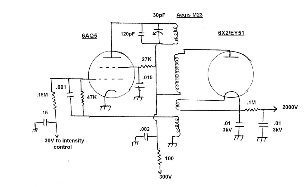
Final circuit of the RF EHT supply.
Some are no doubt wondering, what about the selenium stick rectifiers such as TV-11S which were used in the last generation of monochrome TV's? The thing to keep in mind here is that these consist of multiple selenium cells in series, inside the tube. So the voltage drop is rather high. Not important at 11-18KV, but could be a problem at 2KV. There was also the question of operating at 1Mc/s instead of the much lower 15.625Kc/s in a conventional set. Nevertheless I did try it, and the results were poor as suspected. Output was only 500V.
Brightness Control Supply.
For a reasonable range of brightness control,
about -30V is required for the 5BP1 grid. In the original circuit, a back
bias resistor was the source of this. I initially planned similarly, except
I would make the filter choke part of that resistance. Doing so would not
lose as much B+ voltage, because the voltage that would be dropped across
the choke could be put to good use, rather than be lost separately on the
B+ line. Placing the choke in the negative supply also removes any voltage
stress on the insulation, and electrolytic action that often causes windings
to go open circuit.
However, I could see two ways to get this
negative voltage from the RF supply which would mean no voltage wasting
back bias resistor would be required. One option was to use a back bias
resistor in series with the earthy end of the EHT winding; 30V lost from
2000V being totally insignificant. In fact, I had plans to go one better
and use a 30V VDR instead of an ordinary resistor. The other option was
to make use of the 6AQ5 grid voltage, as it is working in class C. The
grid current is quite high, resulting in about -60V across the 47K resistor.
By decoupling this voltage with a 180K isolating resistor, it was easy
to get -30V for the 200K brightness pot. This is the approach I took.
One final trick I used was to get a free
extra 300V on the EHT simply by returning the earthy end of the secondary
to the B+ instead of earth. It means the supply only has to generate 1700V
and doesn't have to work as hard.
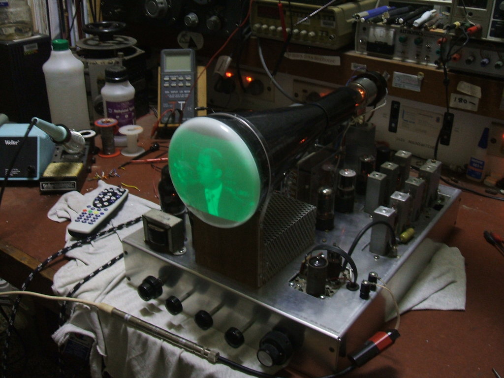
With the EHT supply operating, the box was mounted on the TV chassis and connected into the circuit. Now it was time to get a raster!
First Images.
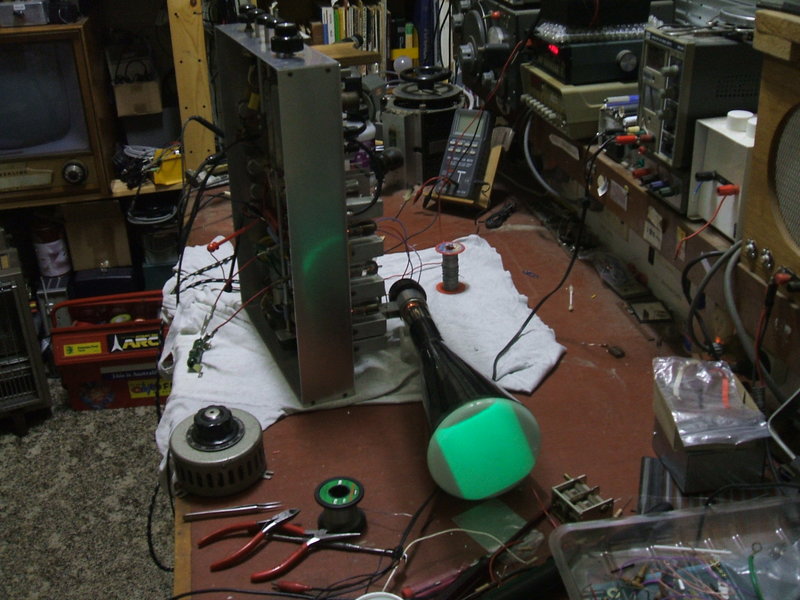
The 5BP1 shows a raster for the first time. Note the rheostat in
the circular metal enclosure. This was to set the B+ to the EHT power supply.
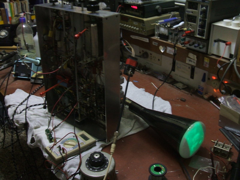
Even though the IF strip was mismatched to the tuner and not aligned
yet, I couldn't resist feeding a signal in. And here is the first picture
on the 5BP1! The green resistor hanging by clip leads from the chassis
is to temporarily provide the 230V rail as this part of the power supply
was not complete.
First thing that surprised me is I had made no major wiring mistakes. A locked picture was achieved straight after adjusting the various controls. I found the focus control didn't have enough range. This turned out to be an omission of one of the 470K resistors in series with the focus pot. Also the 470K from focus pot to earth needed to be 100K. I'd forgotten to check this against my other 5" set - the reason being is I used 500K pots in the picture tube circuit rather than 250K.
EHT Regulation.
As it had all worked out, for a little
over 2000V at the top of the EHT voltage divider, and correct 6X2 heater
voltage, the B+ input to the RF supply needed to be about 260V. Now the
B+ of the set is 300V.
Using a dropping resistor to solve that
problem would be a logical answer except for one thing. I found the dropper
needed to be 850 ohms. Indeed it worked, and the trimmer capacitor could
be tweaked for correct 6X2 heater voltage. Alas, when the set was switched
on, and as soon as the 6AQ5 warmed up, so did the 6X2 - rather brightly!
The 6X2 then dimmed down to normal before the picture then appeared. I
could see a short lived 6X2 in this situation. The reason was clear - with
no load on the supply, as when the 6X2 has not warmed up, and no current
is being drawn from it, the B+ input is much higher than 260V, because
of the loss of regulation introduced by the 850 ohm resistor. Maybe I'd
have
to use a mains transformer after all for the 6X2 heater. I couldn't think
of any solid state diode rated at something like 4000 piv that would work
at 1Mc/s.
So, what if we ran the 6AQ5 plate circuit
from the better regulated 300V supply, and simply increased the screen
resistor to drop the output back to normal? That was the answer. With the
screen resistor increased from 10K to 27K, the trimmer capacitor was adjusted
for correct 6X2 heater voltage. Indeed, switching on from cold only gave
a slight increase in 6X2 heater brightness until it warmed up.
A B+ decoupling resistor of 100 ohms was
retained, but has minimal effect on regulation.
Incidentally, I found the shock off the 2000V supply surprisingly painless. This is the reason RTV&H did not recommend a mains transformer derived EHT supply. These have a much lower output resistance, and require larger filter capacitors, which gives them the potential to be a lethal shock hazard.
Despite the fact that the Matsushita tuner was meant for a 36.875Mc/s IF and the old Stromberg Carlson IF strip was for 36Mc/s, the picture was very good. In reality, there would be of course enough fine tuning adjustment to make the tuner work with the older IF anyway. It was pleasing too that no intercarrier buzz was present in the sound; this being a common problem with some digital boxes and modulators cutting off the carrier on peak whites.
The plan was to realign the Stromberg Carlson video IF strip for the later IF, simply by adding 875Kc/s to all the alignment frequencies. With manual at hand, these were all calculated, sweep generator set up, and alignment commenced. All went well here.
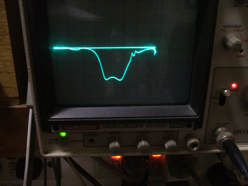
Response curve of the video IF is close to that specified in the
manual.
The RTV&H article shows what appears to be a strip of brass for securing the front of the 5BP1. I followed suit, but found it caused peculiar effects on the raster shape in the corners, and also it caused some picture darkening. It would appear that it was interfering with the charges present around the screen. Indeed, simply placing one's hand on the front of the 5BP1 can cause some grotesque patterns. Replacing it with a Lexan strip fixed the problem.
Typical Pictures.
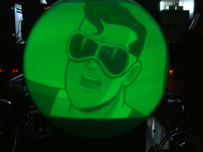
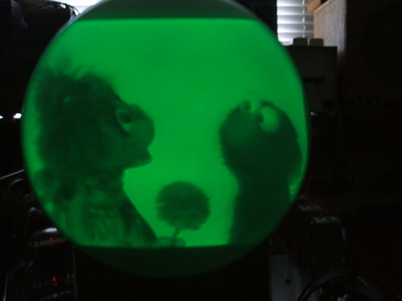
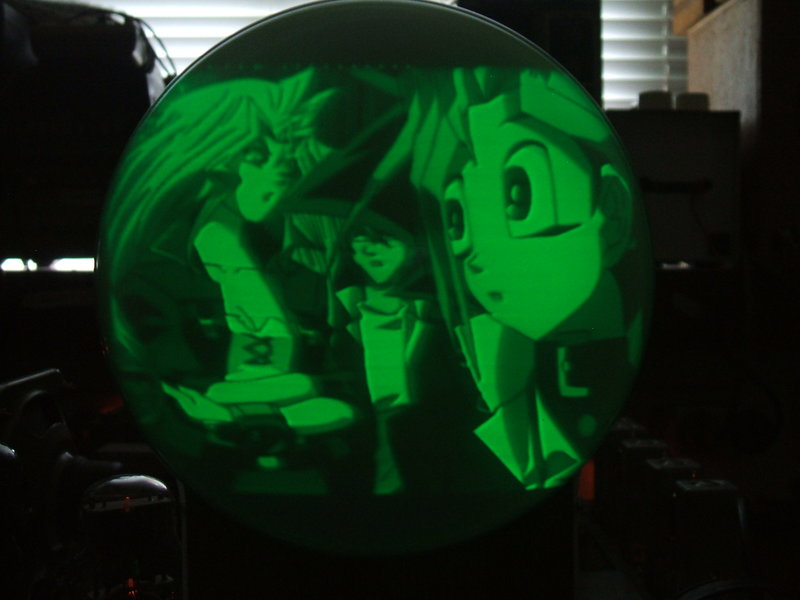
It is very difficult to photograph the pictures and these are only to give an idea of what they look like. The pictures are actually sharper than shown here.
Note the attenuators in the coaxial cable. This is because of a
rather powerful VHF distribution amplifier being used - the simple AGC
is being pushed to its limit.
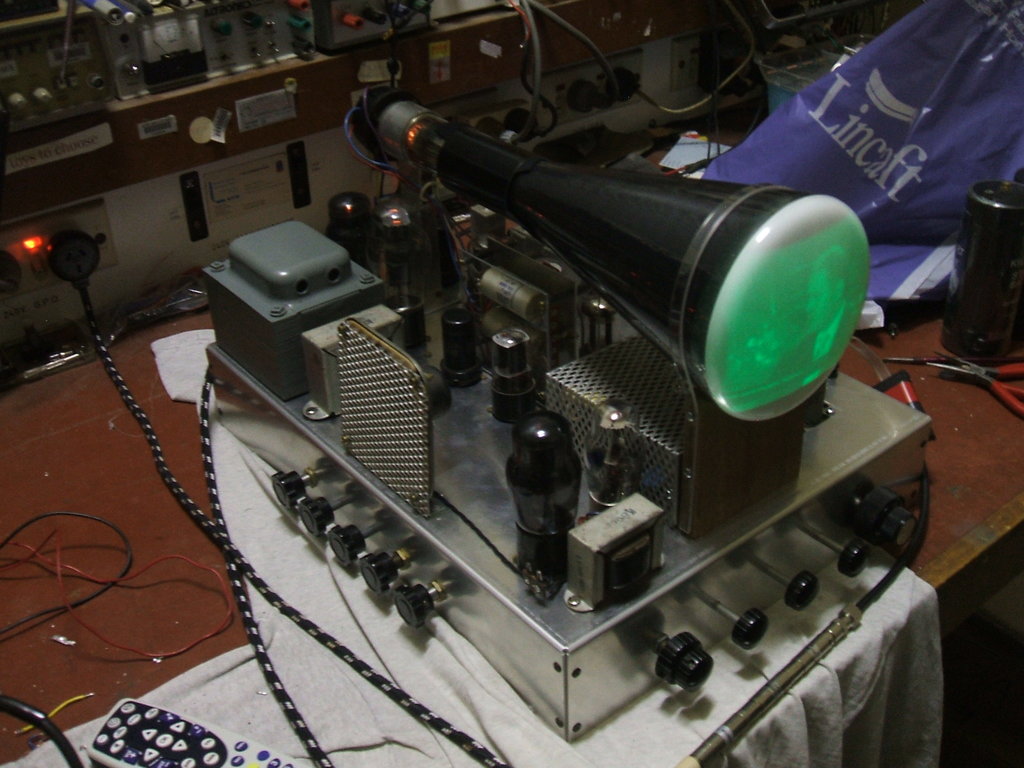
These last two pictures give an idea of the picture brightness in
ordinary room lighting. My workshop is illuminated by a double 20W fluorescent
lamp which is directly above the bench at ceiling height.