TV in the United States
By no means a complete coverage of the subject, this article gives
a background to the development of television in the U.S. and how Australian
TV design was able to draw upon this.
The history of television in the U.S has a rough parallel to
that in the UK; however, in the UK, both radio and TV broadcasting were
government owned and funded by receiving licences. In the
U.S broadcasting was entirely commercially funded.
Mechanical TV in the 20's
As in the UK, there were experiments with mechanical TV in the 1920's.
Most famous of the entrepreneurs was Charles Jenkins whose work paralleled
that of Baird in the UK. However, his system was only able to transmit
sillouhettes; not half tones as with the Baird system.
There were some mechanical sets made by well known companies such as
General Electric. These were often quite ornate console sets and the usual
practice was to include the receiver in the same
cabinet as the scanning disc and neon lamp. Technically, the U.S mechanical
system was superior. Although there were some low definition experiments
using 24 lines, the most common was 60 lines horizontally scanned.
There were also serious attempts at proper synchronisation of the transmitting
and receiving discs. Remember, this was in the days before phase locked
loops and one of the difficulties
with the mechanical system was synchronisation. Because the U.S had
standardised their mains supply at 60 cycles, a popular method was to use
synchronous motors to drive the discs. This
worked well provided the viewer connected to the same power grid as
the transmitter. Another successful method was to broadcast three signals;
two being used for video and sound, with the third being a synchronising
signal. This was amplified at the receiver to drive a synchronous motor
on the same shaft as the normal disc driving motor. The other improvement
over the UK system was to broadcast on short waves. This allowed a greater
bandwidth than the medium wave broadcast band, and thus higher definition.
Bell Telephone Laboratories also experimented with a video telephone system,
around that time, using mechanical scanning.
The start of Electronic TV
It became obvious eventually, as it did elsewhere, that there were
limitations to the low definition mechanical system and that the cathode
ray tube was going to be the future of TV. The two major players were David
Sarnoff (of RCA) with his Image Orthicon camera tube, and Philo Farnsworth
with his Image Dissector. Television was at the time seen as the future
of electronics (this was before WW2) and RCA put all their resources into
TV. [As a sideline to this, RCA had a strong opposition to FM which
they thought would encourage people to buy FM radio receivers instead of
TV sets. Edwin Armstrong (the inventor of FM) was however supported by
General Electric who subsequently set up an FM station in Schenectady].
The first 'standard' was 343 lines with the field rate locked to the
mains; i.e.. 60 cycles. This was upgraded to 441 lines, 60 fields, negative
modulation, and AM sound for the official start of TV
during the New York World Fair of 1939. The first stations
were that of RCA in New York on top of the Empire State building
broadcasting on 44-50Mc/s, and the Columbia Broadcasting System on 50-56Mc/s
from the Chrysler building. At this time there were only five channels
in Band 1. Americans were able to improve upon the British system from
the start. With negative modulation, picture interference was less noticeable
and this was improved on by using horizontal polarisation anyway. Besides,
negative modulation made transmitter design easier and more efficient,
and later when AGC systems were used in receivers, negative modulation
allowed the sync pulses to be used as a reference. Vestigial sideband transmission
was also used before the UK adopted it. [It should be noted that the
decision to use a field rate of 60 fields per second, as determined by
the mains supply, did cause difficulties in televising films taken at the
standard 48 frames per second. Telecine machines required special projectors
to deal with this. With European systems operating on 50 fields per second
films are simply speeded up for showing, the extra two frames per second
not being of significant consequence]
A sample of 1939 TV models.
System Standards
Unlike the UK, TV in the US continued to function and develop during
the War, for it wasn't until 1942 that the US became involved. Around the
end of WW2, the TV system was upgraded. This
time the picture would consist of 525 lines with FM sound and 13 channels.
Apart from dropping Channel 1 by the late 40s, this standard (known as
System
M) has remained in operation.
This change in standards did not cause anything like the upheaval that
occurred in the UK. The only sets at the time were concentrated around
New York and there were not that many of them.
It was also a simple job to convert a 441 line set to the new standard.
The horizontal hold would require resetting or maybe a change in a resistor
value if there was insufficient adjustment to increase the frequency from
13,230 c/s to 15,750 c/s. With low deflection angles and electrostatic
tubes, the line output stages were sufficiently accommodating to work with
this increase. The sound channel would automatically work on FM simply
by adjusting the fine tuning control slightly so that slope detection occurred.
In fact there were still some sets being commercially made with an AM sound
channel (generally cheap kitsets) after the change to FM sound. Some did
go to the trouble of rebuilding the sound channel with a limiting stage
and proper FM (i.e. Travis, Foster Seeley, or Ratio detector) demodulation
stage which was not beyond the capability of any competent TV technician.
FM sound
With the virtues of FM sound transmission known and proved by the late
1930's, it was natural to include it for TV sound channel. Most important
was the immunity to interference, which could be
troublesome on the lower VHF channels. It is important to note that
car ignition systems were the prominent form of interference as most cars
did not have any suppression devices, for car
radios were fitted to the vast minority of cars. Other forms of interference
commonly mentioned at the time include such things as neon signs (and the
motor driven switches thereof), diathermy
equipment and brush type motors.
The first generations of US TV sets used a split sound IF for their
FM sound channel. After all it was the logical progression to substitute
an FM detector for the AM one. Sets were made like this
up until the late 1940's. However, the disadvantage of this is that
any tuning drift becomes very evident. A 100K/cs drift in the tuner's local
oscillator is not going to be so evident in the picture,
but it will take the sound channel right off tune resulting in weak
and distorted sound. Some of the more elaborate sets did actually use the
DC output from the FM tuner to correct the fine
tuning. This split sound method is used universally for AM sound (British
405 line and French 625 & 819 line systems) but is possibly less of
a problem. By making the sound IF strip in the TV
receiver 200Kc/s wide, a fair amount of drift is allowable before the
10Kc/s audio signal goes out of the pass band. Unlike FM, an AM demodulator
does not have to be tuned right on the signal to
provide distortion free sound.
Intercarrier Sound
A major development occurred in the late 40's when sets started to
use intercarrier sound. This once and for all solved the problem of tuning
drift in the sound channel. It also did allow a sound
IF strip of less complexity, and in fact was initially used as a cost
cutting feature in cheap sets. It was realised that as the sound signal
is always 4.5Mc/s away from the video carrier, there would always be the
sound signal at 4.5Mc/s at the output of the video detector. This results
from the beat between the sound and vision carriers being fed into a non
linear device (i.e.. the video detector). The vision carrier is effectively
performing as the local oscillator and converts the sound carrier down
to 4.5Mc/s. Several stages of sound IF amplification can be dispensed with
as the existing video IF strip has also amplified the sound channel. Furthermore,
the video amplifier also contributes gain, and only a limiting stage and
FM detector are required to extract the sound. Because the FM sound channel
is now working at 4.5Mc/s, its alignment is more stable, but more importantly,
because the frequency difference between sound and video carriers is precisely
set at the transmitter, any fine tuning drift at the receiver will not
cause loss of sound quality. (Obviously if the set is mistuned so much
that the video carrier is lost there will be no sound, but this sort of
drift does not occur in a properly working TV tuner). In the US, the FM
deviation is 25Kc/s, unlike 50Kc/s used elsewhere for TV, and the 75Kc/s
used for FM sound broadcasts on the 88-108Mc/s band.
Set design - Electrostatic Sets
Having looked at the differences between the existing UK and the new
US systems, lets look at the sets themselves. The first sets usually had
screen sizes under 14" and were often electrostatically deflected.
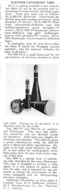
Released in 1939, the 1802P1 and 1802P4 are the pre RMA numbers
for 5BP1 and 5BP4. The 5BP1 was a very popular CRT in Australia for oscilloscopes
and home made TV sets as they were plentiful and cheap after the war as
a disposals item. Wartime saw them used in Pulse Position Indicator (simple
form of RADAR) display use.
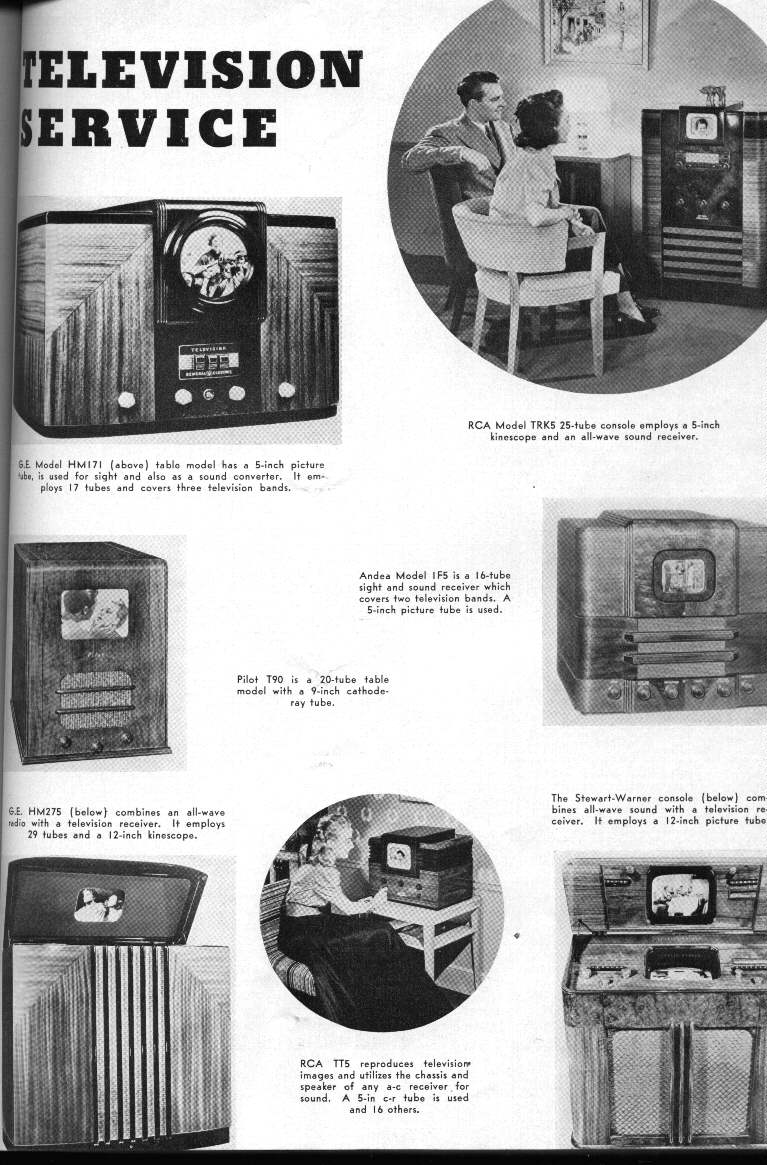
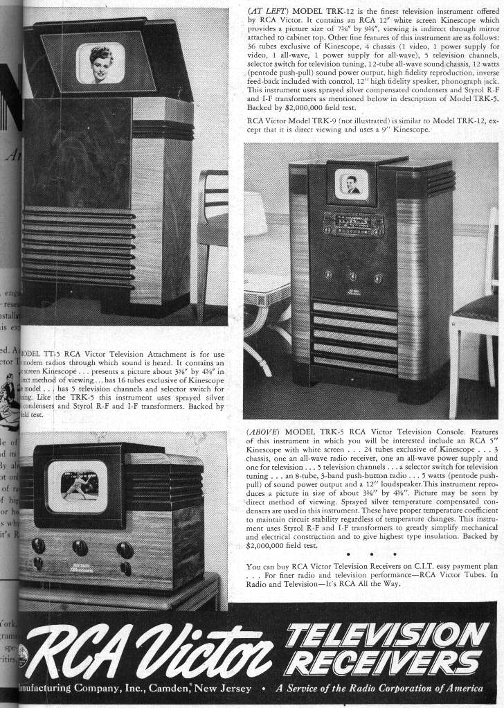
A popular model for the 1939 opening of TV was the RCA TRK-5. This was
a large console set
fitted with a 5" CRT which was either a 5BP4 [1802-P4](white) or a
5BP1 [1802-P1](green). A cheaper version of this set was the TT5 which
reproduced the sound on an existing radio receiver.
The TRK-5
circuit can be seen here.
Unlike in the U.K., thyratrons were not popular as deflection oscillators.
Instead, multivibrators using twin triodes, such as 6F8 and 6N7 were used.
These would drive output stages using similar twin triodes in push pull
mode to drive the CRT's deflection plates. Being all resistance coupled,
there wasn't much difference between circuits of the line and field stages,
except for the values of resistors
and condensers to optimise operation at the respective line and field
frequencies. EHT supplies were usually derived from the mains transformer
with a 2X2 rectifier, supplying typically 2000V. Later electrostatic sets
used an RF power supply with a power tetrode or pentode such as 6V6 or
6Y6 that drove a high voltage RF transformer in a self oscillating circuit.
This was rectified by a 1B3 (formerly known as 8016). The front end
and power supplies of these sets were quite conventional and used standard
sorts of valves that would be seen in other domestic equipment of the time.
The 6AC7 (1852) and its remote cutoff counterpart, the 1853, was commonly
used in the VHF and IF portions with a 6J5 as local oscillator tuning the
five channels.
Detection used the common 6H6. Video and audio output stages used whatever
audio valve was in fashion, such as 6F6, 6K6, 6V6, etc. Diode sync separators
were common, also using the 6H6.
AGC was not used, with the contrast control manually controlling front
end gain by means of adjusting the bias voltage of the RF and IF valves.
DC restoration was often provided for, either by direct coupling from video
amplifier plate to CRT grid or cathode, or by using a diode DC restorer
(again likely to be a 6H6).
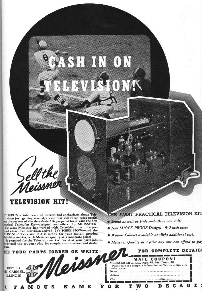
As with elsewhere in the world, kit construction of TV sets was also
popular. One well known model was the Meissner 10-1153. Click
here for the Meissner's circuit
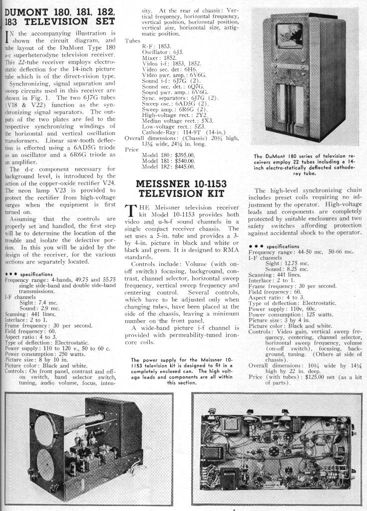
Note from these circuits and specifications that there was no standardisation
of IF's. The only thing that was standard is the difference between sound
and vision IF which is 4.5Mc/s.
 Click
here to see the full size Meissner advertisement
Click
here to see the full size Meissner advertisement
Once CRT development allowed the construction of larger tubes, the electrostatic
sets became relegated to cheap portable sets. Most were 7" using the 7JP4
CRT and were sold by companies
such as Admrial (17T11, 19A1 etc), Hallicrafters (T54 etc), Motorola
(VT71, VT73), Tele Tone (TV149), Sentinel (400TV), and others. There was
also a 3" set; the Pilot TV37, using a 3KP1 or 3KP4 and built into a case
resembling that of a small sewing machine. Belmont produced a 10" electrostatic
set and was the only manufacturer to do so. Spare tubes for this set were
thus quite rare. There were even TV field strength meters for aerial installation
technicians with small electrostatic CRT's, such as National's NC-TV7.
As 'learn at home' type electronics courses were taking off at this time,
these electrostatic sets were also very popular as kits, either by the
course provider or other companies such as Heathkit.
Series heater, live chassis power supplies were used in many of these
sets. This further lowered the cost of these sets as well as making
them smaller and lighter. In this case the rectifiers (selenium or valve)
were connected as a half wave voltage doubler to provide 250VDC from the
110V AC mains. The heater string was 600mA, as dictated by the CRT heater
and 6SN7 triodes, which were universally being used in the deflection oscillators
and amplifiers. This meant lower current heater valves required shunt resistors
across their heaters, or if
currents added up suitably, parallel combinations of heaters. (e.g.
parallel two 6H6 heaters to draw 600mA). It would be a few years yet before
valves became available specifically for series
heater use (by which time this type of set was obsolete). Using valves
ordinarily meant for 6.3V parallel heater use was not without problems
as I pointed out in my Ekco article, as the warm up time was not controlled
thus causing heater failure in the faster heating types.
Because of the limitations of electrostatic CRT's, in terms of large
screen size, they were considered obsolete by the early 50's, even for
portables.
Electromagnetic Deflection
US electromagnetically deflected TV generally kept to a standard design
that evolved into what we see today with the last valve monochrome sets
in the US and Australia. A good example of
1939 electromagnetic sets is the RCA TRK12, a 12" set which also used
the same chassis as its 9" counterpart, the TRK 9. Here
is the circuit. Note that this set has peak level AGC (one of
the advantages of using negative modulation is that it is easy to create
an AGC voltage that is determined by signal level alone and not picture
content). Also note the simplicity of the line output stage using a 6L6
valve with
a 5V4 to damp the negative oscillations. Horizontal AFC was not to
appear for a while, so first generation sets had the line oscillator triggered
directly by the sync pulses. However, this shows up one disadvantage of
negative modulation in that noise pulses are of the same polarity as the
sync pulses, hence the various AFC and noise cancelling circuits that appeared
later on.
One set appeared to be at the forefront of design and was what many
others (particularly no name brands) based themselves on. This was the
RCA 630 which first appeared with a 10" CRT. This set appeared in the 40's
and with many improvements along the way, the last of this chassis in the
50's bore little resemblance to the original design. Unfortunately, the
first generation of electromagnetically deflected CRT's, such as the 12LP4,
suffered from ion burn. The cathode in a picture tube emits ions as well
as electrons. The ions are heavier than the electrons and not as easily
deflected. This means a concentration of ions in the middle of the screen
where they damage the phosphor, leaving a brown spot. By the late 1940's
the problem was understood and CRT's were fitted with ion trap magnets
to pull the ions to the side of the tube neck where they did no harm. Later
tubes had aluminised screens which eliminated the problem altogether as
well as providing a brighter picture. The electrons were small enough to
pass through the aluminium layer but the ions were not.
Electrostatic tubes do not have this problem as the ions are deflected
as equally as the electrons.
Relevance to Australian techniques
The valve types of these early sets are familiar to any Australian
TV enthusiast and so are the circuit techniques except for a few minor
variations. No AGC, no horizontal AFC, using RF EHT power supplies, and
the use of shunt damper diodes across the line output transformer would
be the major differences. By the time TV arrived in Australia in 1956,
such things as gated AGC, line output derived EHT, and horizontal AFC were
well established in the U.S. The design techniques are of particular interest
to us in Australia as many of our sets were based on American designs almost
directly. For two examples, AWA sets here were based on RCA designs,
and Healing used DuMont for their designs. Admiral went so far as to release
a set in Australia that was identical to the US model with only the sound
IF, channel frequencies, and power transformer altered to suit. The video
IF remained at the U.S specification and was the source of much controversy.
In 1956 the valve line up in first generation Australian sets was the same
as their US counterparts (unless it was the likes of Philips, Kriesler,
Astor etc. who based their designs on Philips and Telefunken valves). So
too was the general operation of the set. Multiple channel VHF tuners fed
by ribbon cable from a horizontally polarised aerial, FM intercarrier sound,
negative modulation, horizontal AFC, and parallel heater circuits were
standard in both countries. Apart from some slight frequency differences,
the sets worked the same. As a result, the prolific amount of US written
TV service books that appeared in the 50's and 60's were quite relevant
to Australian technicians. Even RCA and B&K television test instruments
were sold locally with minor modification.
Aerials
Being all horizontally polarised, TV aerials were usually connected
to the set by 300 ohm ribbon. This impedance was chosen as it's the characteristic
impedance of a folded dipole, which is the
basis of the typical Yagi based aerial. Flat twin lead ribbon has lower
loss in typical situations and is cheaper than coaxial cable. Care is required
in keeping the transmission line away from conductive objects otherwise
the line can become unbalanced reducing noise immunity as well a causing
ghosting. To make installation easier, a whole range of standoff insulators
appeared so that the line could be run down the mast, over gutters, down
brick walls, through windows etc. Ribbon cable remained dominant until
the proliferation of cable TV in the 80's. For severe installations in
very strong interference areas, or
where snow settling on the line was a problem, there was even a shielded
version of ribbon cable which we never saw in Australia. Balanced transmission
line was never popular in the U.K, presumably because direct signal pickup
would be more of a problem with vertically polarised signals.
Early receiving aerials were band or channel specific. That means if
you were in an area with channels in Band 1 and Band 3, two aerials were
required. They would be mounted on a common mast with
a matching harness to connect the two together. This matching harness
worked on the principle that at a 1/4 wavelength, an open transmission
line appears as a short circuit and vice versa.
By the mid 50's (and the start of Australian TV) this two aerial system
was out of fashion, and the high / low band yagi was developed which is
still with us. There were also colinear, log periodic,
cross fire and phased array type aerials which we saw in Australia.
For indoor aerials there were hundreds of designs from objects disguised
as picture frames to flexible aerials built into a mat
you laid down on the attic floor. The ubiquitous spiral indoor aerial
which is really an Aussie icon now, had its origins in the U.S.,
being released by the Hi Lo company in Chicago during 1951. With transmission
standards being so similar it was easy to sell the US product here. Best
known of U.S. aerial companies setting up locally was Channel Master who
became involved with Ferris. Their 1057 Challenger model was one
of the first here, using 600 ohm folded dipoles. This was a fringe model,
but more commonly would be seen the Valiant 636 in suburban areas. The
biggest aerial they made was the CX10, a huge log periodic. Their Traveling
Wave aerial supposedly had exceptional directional characteristics but
seemed to have disappeared by the early 60's. Perhaps this was due to the
3110 and 3112
aerials. These were exceptional in their anti ghosting performance.
No other aerial I have seen has been able to cancel ghosts like the 3112.
Along with aerials, Channel Master made
accessories such as masthead amplifiers, mast hardware, splitters etc.
Other large companies were Jerrold and Winegard who we never saw in Australia
until pay TV appeared with Jerrold decoder boxes being used for Galaxy/Austar/ECTV
and Optus. As for the aerial installations themselves, they are much the
same as in Australia, with guyed masts and wall brackets probably being
the most common. However, unlike the U.S, Australian TV aerials virtually
never had their masts earthed or any form of lightning protection provided.
What was popular since the early days of TV in the U.S. were aerial rotators.
Until TV spread across the country, viewers in many areas had to try their
luck and pick up signals from transmitters that might be 200 miles away
in varying directions. This was very dependent on weather and topographical
conditions and therefore not a totally satisfactory solution. Around the
early 1950's, outboard "Boosters" were heavily promoted and all sorts of
extravagant claims were made on being able to pull in signals from 100's
of miles away. These devices were the ancestors of today's masthead amplifiers
and consisted of one or two stages of amplification using valves such as
6J6 or 6AG5. Some were broadband and covered Band 1 and Band 3 separately
by switching coils. Better designs amplified the individual channels using
turret, incremental, or continuous tuning mechanisms as used in the RF
sections of TV tuners. However, their "miracle cure" claims, even when
extra units were cascaded together is doubtful. The reason being is that
these were set top devices and were therefore unable to compensate for
the signal lost between the aerial and set. The noise at the set end of
the transmission line would be amplified as much as the wanted signal.
The correct place to have such an amplifier is of course, right at the
aerial. If there is no signal at the aerial to start with, then even the
highest gain amplifier will be useless. Where these gadgets would be useful
is if the set has poor front end gain, which at the time was not unusual.
It wasn't until the cascode and neutralised triode circuits appeared in
the 50's and 60's that receiver gain became as good as it is now.
Cable TV
Cable TV of the 50's wasn't hundreds of channels of movies and sports
as it is today. It actually started as a need to get the city channels
into isolated rural communities. What usually
happened is that the local electrical/radio shop would discover that
signals were sometimes receivable in their town and start selling a few
sets with huge towering masts supporting the
aerial to go with them. Someone would soon find out much more reliable
reception would be available at the top of a nearby hill and so the local
tv guy and a few others would set up a cable
distribution system, forming a cable company. Coaxial cable would be
strung between power poles, with valve distribution amplifiers placed where
necessary to prevent signal loss through miles of
cables and tap offs. Each subscriber would pay an ongoing fee for this,
and to have a 75 ohm coax cable connected to their house. All this would
be fed from the aerial at the top of the hill, fitted with a masthead amplifier.
Later it was realised how easy it was for a local consortium to feed other
signals into that same cable and so a local channel unique to that town
could easily be established without the additional expenses of setting
up a transmitter, getting FCC approval etc. Another method used which the
FCC frowned upon was to set up a receiving aerial at the top of a hill
and amplify its signal, retransmitting it down to the town's inhabitants.
The cable system spread to the cities which already had terrestrial
transmitters, in view of the extra channels that could be sent down it,
and used as a basis for pay TV that we know today.
Additionally, some rather conservative communities disliked TV aerials
sprouting from every rooftop, and not all areas had good off air reception
anyway, so this only increased cable's
popularity.
Pay TV
There were concerns during the early 1940's that TV would not be able
to fund itself. With few sets there were few willing to advertise on the
new medium. One solution was thought to be to
broadcast special programs, after normal viewing hours, that would
be transmitted free of advertising. Only viewers who paid would be able
to watch these programs.
So as not to interfere with the normal schedule of the station, these
programs would be broadcast when the transmitter was not normally on air.
This was a serious downfall as few
would want to start watching a concert at 11pm. Obviously to get people
to pay, an encoding system had to be devised to prevent non payers watching
the program. The two methods used in the 1940's were 'Phonevision' and
one requiring a specially punched card to be inserted into an adapter connected
to the TV set. This was another downfall of early pay TV; the set had to
be modified to use a decoder.
Phonevision was trialled in Chicago and required a connection to the
telephone line. This was really a pay per view system as the subscriber
called up Phonevision who then sent synchronising pulses down the phone
line which would then be fed into the sync circuitry of the TV set allowing
a locked picture. (The Phonevision signal as radiated from the transmitter
was devoid of sync pulses). A disadvantage can be immediately seen here,
as requiring another phone line to be installed if anyone is to use the
telephone during the program.
The punched card system also worked on disrupted sync pulses. The
sync pulses would be shifted so as to give a very ragged edge to the picture.
In this system, the decoder contained a
miniature CRT in front of which the punched card was placed. In front
of this again was a phototube, the signal from which recreated the correct
sync pulses. The small CRT was
synchronised to the off air signal and had it's Z axis modulated such
that if the card had the correct punching, light would emanate through
the card at the correct time for each sync pulse.
The problems with this system is an expensive decoder with CRT and
HV supply but more importantly cards are easily duplicated.
Pay TV was a very short lived failure due to the restricted and inconvenient
time slots. Additionally, Phonevision was disliked by the telephone company.
It did not reemerge until many years later on cable and satellite systems.
Colour TV
It is not the aim of this article to go into the details of colour
TV systems, but some of the development will be discussed here, as colour
TV initially started off with converted monochrome
TV receivers. In 1949 CBS proposed a simple colour TV system using
a partially mechanical system. By placing a three section coloured filter
in front of a monochrome camera and receiver,
and having it rotate rapidly, it was possible to transmit and view
the colour component. However, to avoid colour flicker being evident it
was necessary to increase the field rate to 144c/s instead of 60c/s. This
would immediately cause the video signal to require more than 4.5Mc/s of
bandwidth, so this and the sound would not fit in the FCC specified 6Mc/s
channel. Therefore, the line rate was dropped to 405 lines. The colour
sets were actually dual standard, so they could be switched from the normal
525 line 60 field system, with the colour disc removed, to 405 lines 144
fields when a colour program was on. It was of course possible to see the
colour program in monochrome without the disc as the signal consisted of
the red, green, and blue components sent sequentially. Thus three fields
would need to be sent to make the complete colour picture. Fairly obviously
this was not a compatible system. While CBS argued that the mechanical
components could be replaced with tri colour picture tubes when they became
available, the signals could not ordinarily be viewed on existing monochrome
sets. Unless a viewer had a colour set, or a set with its timebase circuitry
modified, the programs could not be viewed. With millions of 525 line 60
field sets in use this was going to cause problems. Converting them all
would be a huge task, and it was already fortunate that the low angle deflection
circuitry used at the time seemed not to mind being run at frequencies
it wasn't designed for. Electrostatic sets are no problem for this sort
of modification. CBS did not make these sets but simply implemented the
standard.
Although the performance of this system apparently gave good colour
reproduction, there was some colour smearing on moving objects. RCA was
determined not to let CBS win the colour battle with their mechanical and
incompatible system. RCA knew that colour TV would have to be all electronic
and compatible to be practical and retain the existing monochrome viewers.
The transmitting end consisted of three separate camera tubes with red,
green and blue filters as is still done now. At the receiver were three
projection type cathode ray tubes, with corresponding coloured filters.
Two remaining problems were to make this RGB signal compatible and to have
one direct view picture tube for viewing. One compatible system that did
have good results was the dot sequential system where the each pixel consisted
of the RGB pixels sent sequentially. A monochrome set would simply average
the three signals into a luminance signal and thus provide a proper monochrome
picture. RCA then realised that most of the picture detail is in the luminance
(i.e. black and white) part of the picture, and that also by using a simple
matrixing circuit it was only necessary to transmit two low bandwidth colour
signals. One variant of this system simply transmitted the green signal
as the luminance signal. Monochrome sets would still produce a reasonably
accurate picture as most scene content is in fact largely green and it's
this colour that the human eye is most sensitive to. This is why green
is 63% of the colour signal in modern systems. However, this system still
required the red and blue (although of lesser bandwidth) outside the channel.
Finally, RCA achieved their aim by the early 50's with what came to
be called the NTSC system and their tricolour shadowmask picture tube.
The monochrome signal was transmitted as before, but the red and blue colour
difference signals interleaved in the monochrome signal. As the FCC was
on the verge of approving the CBS system, RCA was pressured to meet a deadline.
Unfortunately NTSC, while it achieved a great deal in terms of compatibility,
was an inferior colour system from the start. The problem is that phase
distortion corrupts the hue of the received picture and although RCA experimented
with various types of automatic correction (along the lines of PAL), it
was never implemented, leaving NTSC being known as "Never Twice Same Colour".
To this day, NTSC pictures still suffer from 'green faces' and sets require
a manually adjustable control to try to correct this. It wasn't until European
work in the late 50's brought PAL and SECAM into existence, eliminating
this weakness of NTSC. The scanning rates were changed slightly upon the
introduction of colour so as to obtain a suitable frequency ratio to the
colour subcarrier. The line rate was now 15,734 c/s and field rate 59.9
c/s.
UHF
By the early 1950's, experiments were being done to assess the viability
of using UHF for TV broadcasting, in view of wartime developments, as a
solution to the crowding problem becoming evident in the VHF band. By about
1951 it was seen as successful enough to broadcast TV on and UHF stations
have existed ever since. Of course existing TV sets could not receive the
new transmissions so various methods were used to overcome this. The most
popular was a set top converter, converting the UHF signal down to an unused
VHF channel. Typically these devices used a lecher line tuning arrangement
with a 6AF4 UHF triode and 1N28 diode as a mixer. It can be seen that such
a device is fairly lossy with passive mixing and no RF amplifier. Tuners
built into the TV itself took two forms. One used an existing VHF turret
tuner with one of the biscuits replaced with one for UHF. This incorporated
a diode to generate a harmonic from the existing VHF local oscillator.
The limitations of this would be restricted tuning range (dependent on
the range of the VHF fine tuning) and rather poor gain. The other way which
was with us right up until the 1980's and the end of mechanical tuning,
was along the lines of the UHF set top converters but used a variable capacitor
in the UHF tuner built into the set. Again, a 6AF4 was used with a mixer
diode, but the converter in the existing VHF tuner was incorporated to
perform as the first IF stage providing some additional gain. By switching
to the "U" position on the VHF channel selector, B+ would be fed into the
UHF tuner, and the IF from the UHF tuner fed into the VHF mixer valve.
Output from here was sent to the set's video IF strip in the usual way.
Of course set makers were reluctant to include UHF tuners as standard.
This was seen as a hindrance to the UHF cause, so in 1963 it became legislation
that all new sets had to have a UHF tuner fitted. (It is unfortunate this
didn't happen in Australia...there were sets still on sale here with VHF
only tuning even after the advent of UHF only stations).
The aerials for UHF were always much as they are now, with bow tie
and yagi designs being the most popular. Combined VHF/UHF aerials appeared
later on. As with VHF, 300 ohm ribbon was
preferred due to low losses. There were some types of ribbon cable
that were air spaced or slotted to reduce loss in wet weather. US TV sets
had two sets of 300 ohm aerial terminals, so separate transmission lines
had to be run from the VHF and UHF aerials. By using diplexers it was possible
to combine both VHF and UHF into one length of ribbon, but the losses can
be considerable, especially when there is no RF amplifier in the UHF tuner.
With the popularity of cable systems and therefore coaxial cable, 300 ohm
screw terminals gave way to coaxial connectors of the "F" variety. Outdoor
aerials also became a dying breed in urban areas. With the advent of satellite,
cable, and digital TV, the F connector is now becoming the standard worldwide
connector for 75 ohm TV applications.
back to homepage


