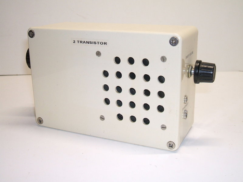
Two transistors provide loudspeaker reception with no external aerial.
Two transistors provide loudspeaker reception with no external aerial.
In the modern day, few would have heard of the reflex receiver, but for a time it was a very popular circuit. The concept was that one transistor would provide RF amplification of the incoming signal, it would be detected, and then the audio fed back through the same transistor for further gain. At this point, the signal is strong enough to drive an earphone, but with a second transistor, speaker operation becomes possible.
The reflex circuit has been around since the 1920's for valve use, and was used for economy reasons. Making one valve do the job of two could make for a less expensive receiver. One must remember that electronic components were considerably more expensive than now, and this applied particularly to the valves themselves. Valve reflex circuits have been described here and here.
When transistors first appeared commercially in the mid 1950's, their cost was also very high, and thus the reflex circuit was revived once again. Because of the low component count, it suited small earphone-only personal portables, and pocket size loudspeaking radios. Throughout the 1960's, the reflex circuit was common in electronics magazine projects, particularly in the UK and Europe, as it was a simple way to make a receiver with good performance, but without the complexity and expense of a superhet. It was also a popular circuit in Japanese electronics kits - particularly the Denshi Block series.
How the reflex circuit works.
For the purposes of acquainting ourselves,
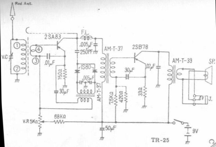
the circuit to be described is that of the Crown TR-25. This was one of
the few reflex sets imported into Australia. All the circuits follow the
same principles, but as will be described later, there are some variations.
The tuned circuit is a typical ferrite
rod loopstick as used in millions of transistor radios. Variable condenser
V.C. tunes the coil in the usual way. The RF signal is fed into the 2SA83
transistor by means of a secondary winding of a few turns. This is necessary
because of the low input resistance of the transistor. Again, this is standard
transistor radio practice.
RF Amplifier.
The 2SA83 is a typical Japanese PNP germanium
transistor of the 1960's. Being PNP, the supply rail is of course negative.
The base is fed with the low impedance RF signal of the wanted station.
The transistor operates as an untuned RF amplifier, with RF choke "F.L."
as the collector load. The 9V supply is fed to the RF choke via the primary
winding of the first audio transformer, AM-T-37. There is negligible DC
voltage drop across the primary winding. RF bypassing for the RF choke's
supply is performed by the 0.005uF condenser. This prevents RF signal being
lost across the audio transformer.
Base bias for the transistor comes from
the voltage divider consisting of the 68K resistor and 5K potentiometer.
Since the bias is adjustable this way, the 5K pot varies the gain of the
transistor, and so functions as the volume control. Bias stabilisation
occurs by means of the 150R emitter resistor in the usual way. The 0.01uF
in the base circuit prevents loss of gain because of the degeneration that
would otherwise occur, due to the emitter resistor. It can be seen that
the RF signal from the ferrite rod is applied directly between the base
and emitter.
Detection.
The amplified RF present at the collector
now proceeds via the 250pF to a half wave voltage doubling detector using
1S80 germanium diodes. Detected audio now appears across the primary of
another AM-T-37 audio transformer, and is filtered by the two 0.005uF condensers
across it.
The secondary of the transformer contains
only the audio signal from the received station, and if an earphone was
to be connected here the signal could be heard.
Reflexing.
At this point, the circuit is simply that
of a one transistor TRF receiver; the signal from the ferrite rod being
amplified, and then detected. However, we can considerably increase the
resultant audio signal, by feeding it through the same transistor, this
time using it as an audio amplifier.
Now, examine the audio transformer secondary
connection. Let's follow its path. One side of it connects to the 2SA83
emitter, via a 30uF condenser, and the other side connects to the base,
via the ferrite loopstick secondary. Again, we see the audio signal is
impressed between base and emitter, ready to be amplified. The 30uF simply
isolates the DC present in the bias circuit, while passing the audio signal.
The 0.01uF referred to previously in the base circuit is an effective RF
filter, but at AF it has little effect, so the audio passes through as
if it was not there. The secondary of the aerial coil is only a few turns,
and again has no effect on the audio signal passing through it.
As the transistor is now operating as an audio amplifier, at the collector is a much stronger audio signal. The RF choke inductance, while significant at RF, has little effect at AF, and for all practical purposes my now be considered a wire link. LIkewise the 0.005uF bypass has no effect on the audio signal and appears as an open circuit. The 250pF appears largely as an open circuit at audio frequencies, so the detector diodes are effectively out of circuit. The audio now appears across the primary of the second AM-T-37 transformer, and is of much greater amplitude than it when it was first detected. A crystal earphone connected here would provide reasonable volume in strong signal areas.
Output Stage.
This is a conventional class A power amplifier
which brings up the audio level to the point where a speaker can be driven.
The 2SB78 is another Japanese PNP germanium transistor, but designed for
audio use only. The circuit is completely conventional. Base bias
comes from the voltage divider consisting of the 75K and 420R resistors.
Emitter stabilisation occurs by means of the 33R. If the emitter current
should increase due to heat or the particular transistor having a higher
than normal gain, more of a voltage drop occurs across the 33R. This in
turn causes the bias to be reduced, since the base is at a fixed voltage.
Normally, there would be loss of audio gain by having the emitter resistor,
since the audio voltage across it would subtract from that between base
and emitter. However, a 30uF condenser prevents this by coupling the audio
from the transformer secondary directly between the base and emitter.
Collector load for the transistor is the
primary winding of the speaker transformer. This feeds the relatively low
impedance speaker in the normal way. Some tone correction is provided by
the 0.02uF bypass condenser. An earphone socket is provided for a
low impedance (8 ohm) magnetic earphone. It disconnects the speaker via
the normally closed contacts in the socket, when in use.
Regeneration.
A further increase in RF gain can be obtained
by including regeneration (positive feedback). If the RF amplifier has
sufficient feedback to almost cause oscillation, gain is increased considerably.
Many reflex sets do not include it, but some, such as the Crown TR-25,
do. Here it is obtained by the gimmick capacitor between the 2SA83 collector
and the top end of the aerial coil. Typically, the amount of regeneration
is set so that at no part of the band does the receiver actually start
oscillating, since this would confuse non technical users. Some sets also
have an optional telescopic aerial to increase the signal input. This is
usually connected to the top end of the aerial coil for maximum coupling.
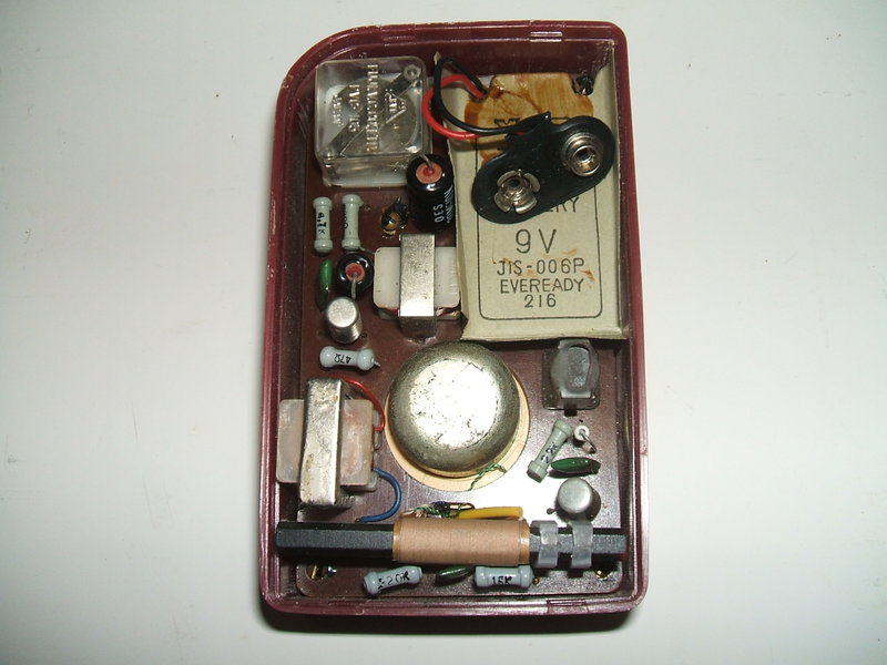
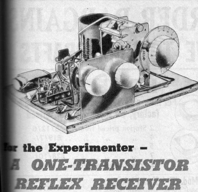
A Homemade Clone of the TR-25
The introductory photo is a reflex set
I built a few years ago based on the Crown circuit. Here, we see what's
inside:
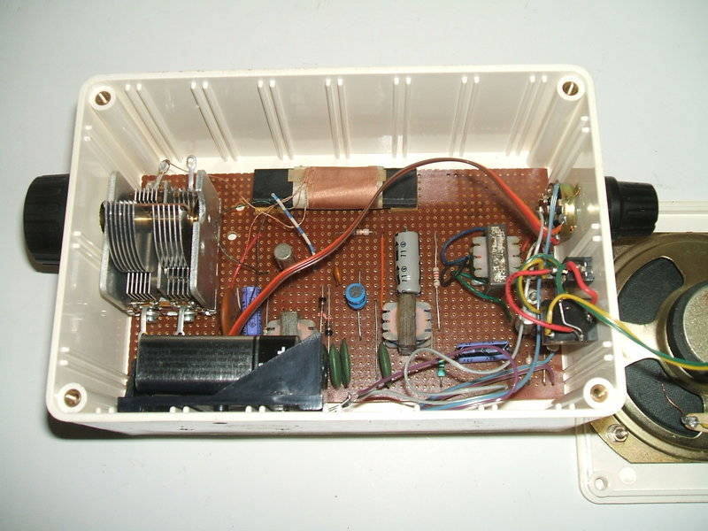
I duplicated the circuit using available
parts. Instead of making a PCB, I built the circuit on Veroboard. It is
housed in a plastic case, and uses a 3" speaker. It will be noted that
the Crown circuit does not use preferred values for many of the resistors
and condensers, so this was one minor change that had to be made. A standard
miniature ferrite rod aerial was used, but the tuning condenser is a large
MSP (AWA) air spaced type. Only the aerial section is used. The RF transistor
is an AF114N, and the output is an AC128. The two interstage transformers
are ordinary miniature transistor types with a primary of 3K and a secondary
of 1.5K. The output transformer is 1K to 8R. The RF choke is 4.7mH. I used
0A47's for the diodes.
A close look at the photo shows a piece
of wire with blue and white stripes near the aerial coil. This provides
the capacitance for regeneration. It is positioned near the ferrite rod
and adjusted so that oscillation can just be achieved across the band at
full volume.
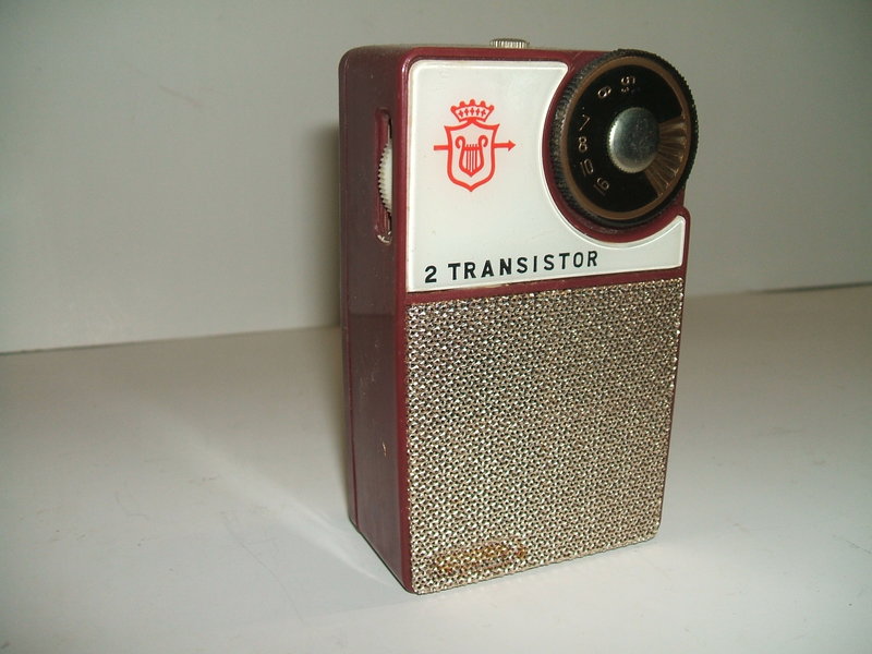
This 1960's Japanese made "Mellotone" receiver is one of many commercially
made reflex receivers.
The Mellotone uses a 2SA353 for the RF transistor, and a 2SB77 for the output. It uses RF transformer coupling and a single diode detector. It does not have regeneration. The location of the ferrite rod is not optimal. While it is away from the battery, it is at the base of the set, so when held in the hand or stood on a surface, reception can be affected.
Two Transistor.
A Japanese series of electronic kits appeared
in the 1960's, under the name of Denshi Block, made by Gakken; a company
that still exists. Two of their modern day radio kits have been described
here.
The components in the Denshi Block kits are mounted in transparent plug
in blocks, and these are assembled on a baseboard with various connecting
links.
The first generation of Denshi Block kits
had opaque blocks. On each block the schematic symbol is printed, so once
the circuit is assembled, one can read the circuit diagram and see the
components physically connected thus.
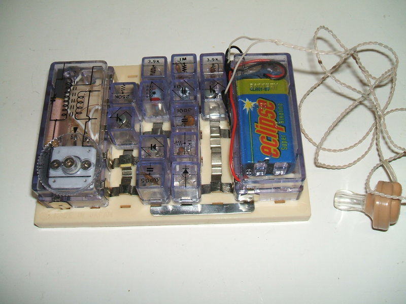
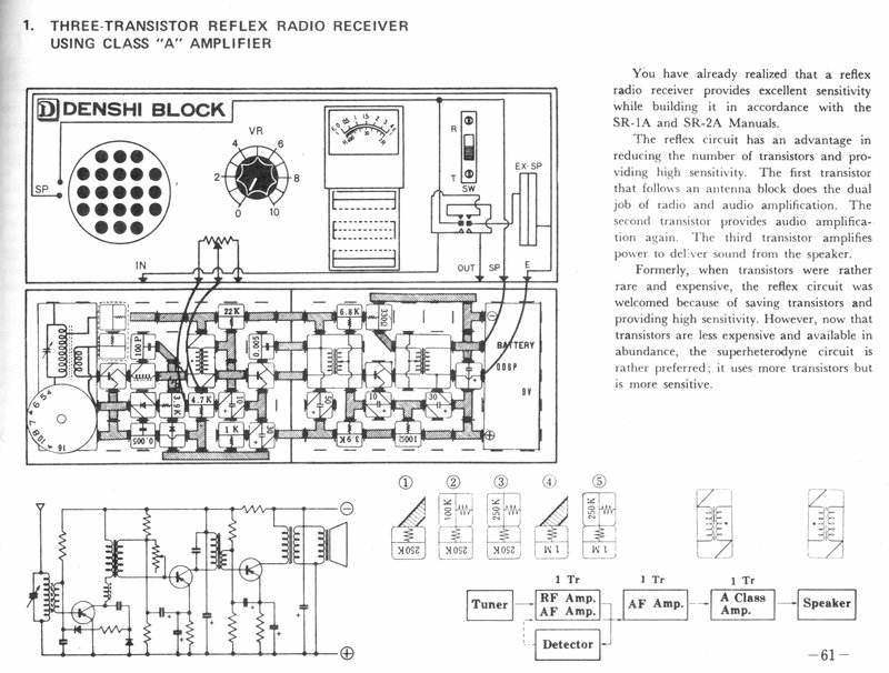
Two transistor reflex receiver from the Denshi Block SR-2A kit.
The Denshi Block SR-3A kit is actually where I first encountered the reflex circuit, back in 1976. Quite a range of reflex circuits can be built, with from one to three transistors, using resistance or transformer coupled audio stages, and with earphone or speaker operation. The circuit to be described is a two transistor resistance coupled design, driving a crystal earphone.
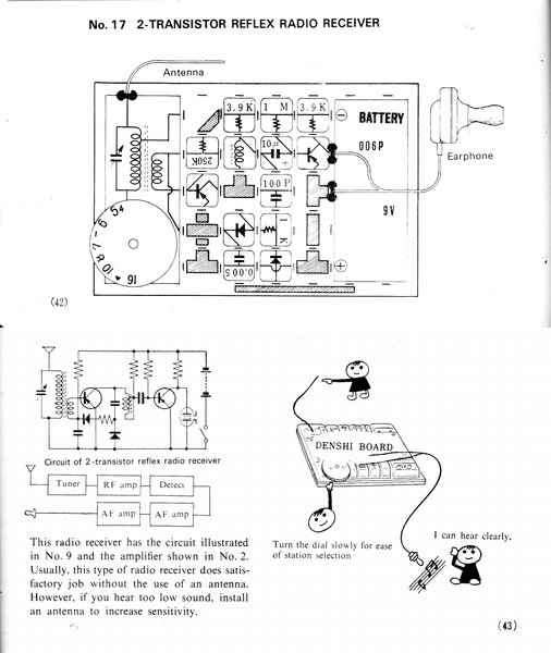
Circuit for the receiver in the above photo.
The above circuit is typical of those presented for construction. This particular one is from the smaller SR-2A kit, which has only two transistors. The SR-3A kit incorporates all the SR-2A circuits, but includes a greater range of components, including a third transistor, two speakers, an LDR, a solar cell, etc. Its also has a somewhat sophisticated appearance, with two baseplates mounted on a 'console' with speaker, switch, and potentiometer.
No regeneration is used with the Denshi Block radio circuits. The transistors are again PNP germanium types, the RF type being a 2SA353, and the audio type being a 2SB172. The diodes are germanium types, which is essential for this type of circuit, unless a bias circuit is included. This is because germanium diodes start conducting at a much lower voltage than silicon types. Typically, a germanium diode is fully biassed at 250mV, whereas silicon requires 700mV. It can be seen the receiver would be very insensitive if silicon diodes were substituted.
Looking at the circuit, we see some differences compared to the Crown design. The RF amplifier is simply biassed by a 250K resistor. The collector load is a 2mH RF choke for the purpose of developing an amplified RF signal, but now the audio load is a 3.9K resistor instead of a transformer. A voltage doubling detector is again used, but feeds the RF amplifier base directly without a transformer. The audio output is resistance coupled, with a 3.9K collector load, and a simple 1M bias resistor. A strange feature is the 1K resistor in series with one of the diodes. It appears to serve no purpose, and unfortunately, while the kits are very well made, the "instructions" do not say anything about the circuit design, at component level. Incidentally, while experimenting with the 250K resistor, I managed to destroy the 2SA353 (I inserted the resistor 90 degrees out of position which put the full 9V across the base-emitter junction). I used a 2SA52 to replace it with, keeping in with the Japanese transistors. Performance was identical, if not slightly better. The choice of bias resistor really depends on the individual transistor used, in the case of where the bias circuit is not stabilised. Possibly, the transistors for these kits were all selected so they had a similar beta (current gain).
Three Transistor.
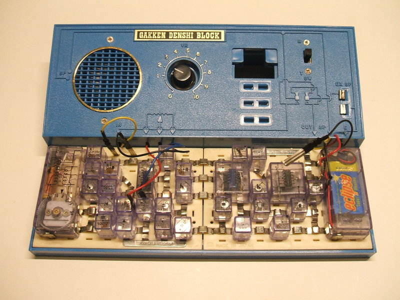
This circuit is built using the SR-3A kit.
This design provides the highest gain of all the reflex receivers in the Denshi Block kit, having three transistors, and being transformer coupled. Some refinement to the operating conditions of the RF transistor can be had by adjusting its bias, as seen by the various combinations of resistor in diagrams 1 to 5. The volume control is of the variable shunt type across the first audio transformer. It effectively short circuits the audio signal with the control in the minimum position. While it does work, control is abrupt. The potentiometer is 50K which is too high for this application. I found much better control could be had by connecting the potentiometer as a voltage divider across the decoupled 9V supply, and feeding the RF transistor bias resistor (I used 250K) from the wiper.
Unlike the previous circuits, the detector is a single diode, not a voltage doubling configuration with two diodes. However, the diode does have some forward bias to improve sensitivity. Also, instructions for including regeneration are included.
Ladybird Books - How to Build a Transistor Radio.
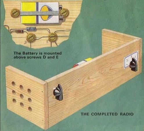
The ferrite rod must not be secured as shown! There is a
shorted turn around each end that will seriously impair performance. Use
plastic clips instead.
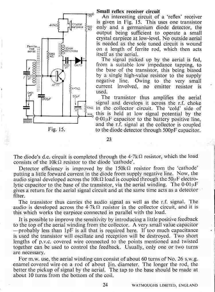
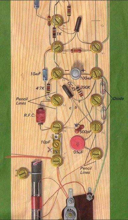
This English book describes the construction of a reflex receiver, starting with a crystal set, and adding to it in stages. The final circuit is a three transistor reflex circuit. The method of construction avoids any soldering, by screwing the components to a piece of wood, using brass screws and cup washers. There is a serious mistake in that the ferrite rod is shown with tinned copper wire wrapped around it, which is then screwed to the baseboard. This will create a shorted turn and seriously affect operation. Presumably, this was not noticed in the author's construction because of the very high signal strength of the BBC transmitters.
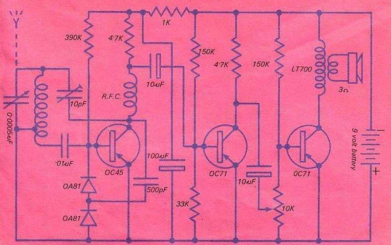
The circuit design is typical, and includes regeneration. The output stage is not stabilised, and the 150K might need to be adjusted to ensure a collector current of around 10mA depending on the actual output transistor. The LT700 transformer has a 1K primary. The method of volume control is one which has been used in some transistor circuits, but is crude because it works by short circuiting the input signal, rather than acting as a voltage divider. This book can be downloaded from the internet for those who want more details.
Sinclair Two Transistor Pocket Radio.
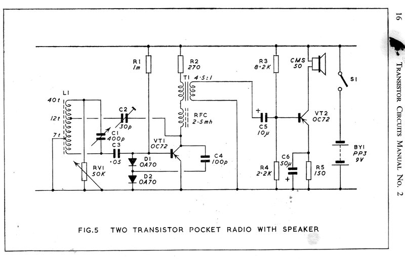
This design appeared in Clive Sinclair's
"Transistor Circuits Manual No. 2". No details are provided about the speaker,
except for the part number. It is more than likely to be about 80 to 150
ohms, looking at other circuits of this type in other English publications.
Regeneration is provided by the 30pF trimmer.
It is preset, and so the volume control RV1, is used to control it. The
method of volume control is crude, simply shunting the aerial coil. The
use of an OC72 for the RF transistor is a mistake. It is meant to be an
OC44. This is pointed out in the text, so it is curious why the circuit
diagram was not amended before publication. An OC72 will not function since
it is an audio only transistor.
Clive Sinclair went on to produce various
commercially made electronic products, including the well known "Micromatic"
key ring radio. This was a two transistor set with earphone-only operation.
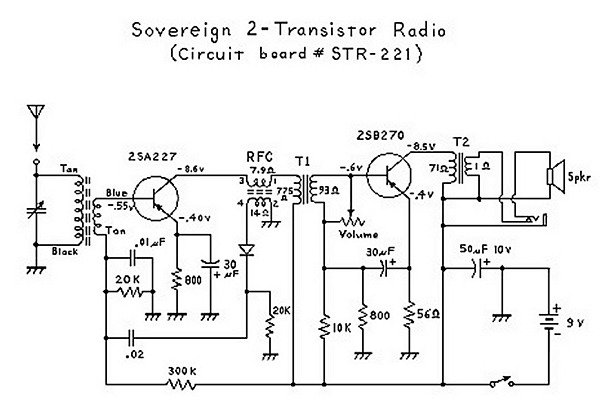
This Sovereign receiver uses an RF transformer instead of an RF choke as the first transistor collector load. It also uses a single detector diode. Bias for the RF transistor is stabilised, but not adjustable. Instead, the volume control is a crude arrangement whereby the secondary of the audio coupling transformer is progressively shorted out with a 5K pot. No regeneration is shown, but it does have an optional telescopic aerial.
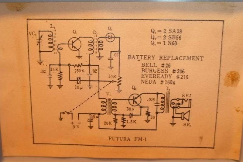
This Futura also has fixed, but not stabilised, bias for the RF transistor. Note no emitter resistor. Like the Sovereign, an RF transformer is used as the collector load, and the secondary feeds a single diode. This time, the volume control adjusts the audio level from the detector before feeding it back into the first transistor. Again, no regeneration is shown.
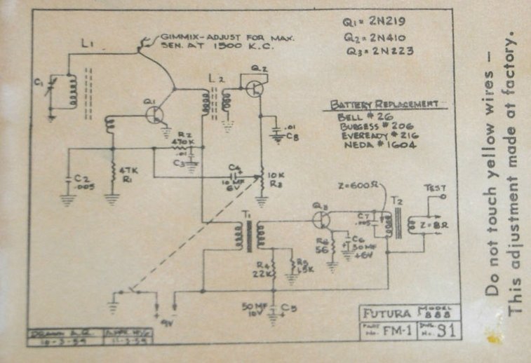
A very similar Futura set does have regeneration, adjusted by a gimmick capacitor. It is otherwise much the same as the previous circuit, except a transistor is shown instead of a diode for the detector. This would prevent it being sold as a "Boys Radio", and is no doubt a marketing strategy - the more transistors, the more upmarket the set appears to be.
Earphone-only Futura.
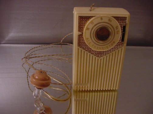
For the time, the reflex circuit allowed miniature sets to be made,
especially when a speaker is not included, such as with this Futura.
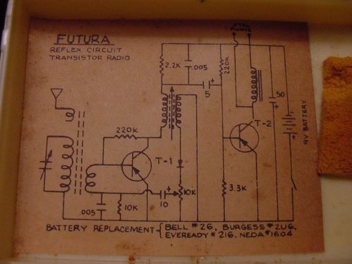
Different again to the previous circuits, this drives a crystal earphone and has no speaker. T-1 uses shunt bias by means of the 220K resistor. It is stabilised by this resistor being fed from the collector, which has a 2.2K load resistor. The RF signal is coupled to the detector by a transformer, and again, a single diode detector is used. However, the audio coupling is of the RC type instead of a transformer. The 2.2K and 5uF couple the audio to T-2. Instead of an output transformer, the load here is simply an audio choke which feeds the earphone. T-2 does not have stabilised bias, which is presumably acceptable due to the low collector current, as compared to output stages which drive a speaker.
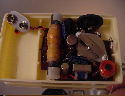
The RF transformer is at bottom right. Note that it is adjustable with the slotted ferrite slug. It would have been better to reverse the PCB so the ferrite rod was near the top of the cabinet and not adjacent to the battery.
Walkie WR8806B
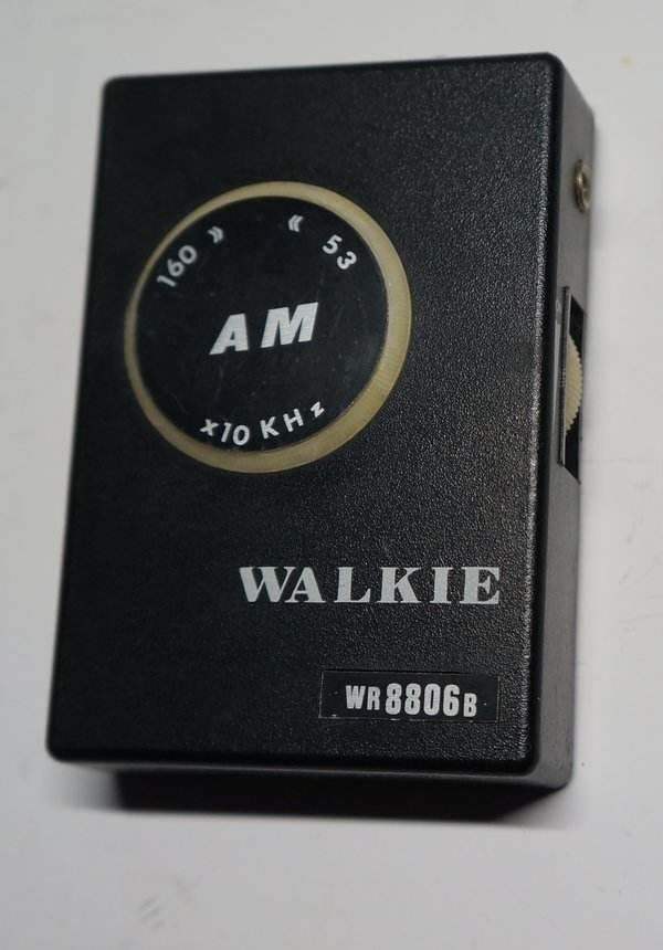
This set was sent to me by a very kind reader. It's slightly unusual in that for an earphone only set it has three transistors. Also, it works from 3V (2x AA cells).
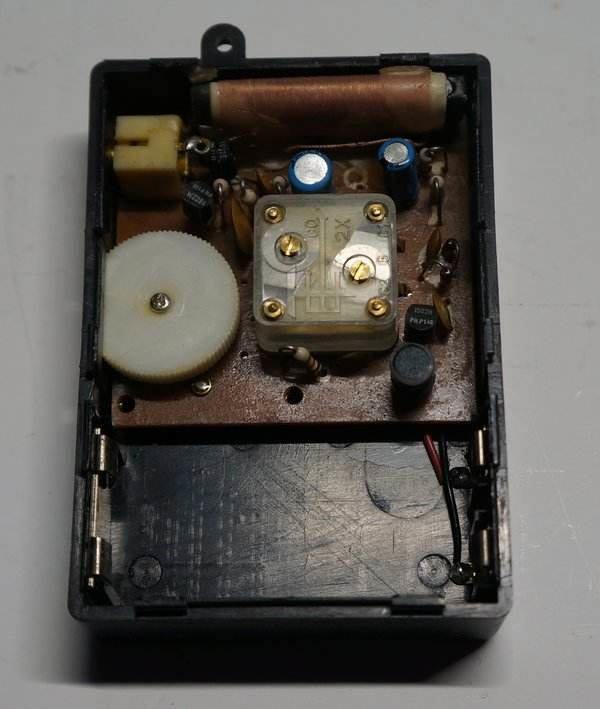
The front end is quite conventional, based
around a 1502H silicon transistor, which appears to be of Philips manufacture.
The value of RF choke is not known, and was not measured, but is assumed
to be 4.7-10mH. It is unclear if the diodes are silicon or germanium, since
there are some germanium types that look like the ubiquitous 1N914 kind
of diode. It would appear that the transistor might not receive full bias
if they were germanium, since the base voltage would be limited to around
500mV (two ge diodes in series). One strange thing is the RF bypass (0.005uF)
for the first transistor is returned not directly to earth, but the 0.01uF
base bypass transistor. This seems to be simply for convenience of the
PCB design. It is just possible this was done to introduce a small amount
of regeneration, but the performance of the set does not suggest this.
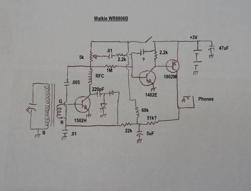
The collector load, in terms of the audio
signal, is a 5k potentiometer. This feeds a two stage amplifier, using
an NPN and PNP silicon transistor. The earphone forms the collector load
of the 1802M output transistor. The three transistors are direct coupled
in terms of biassing so that there is a degree of automatic stabilisation.
The "51k" resistor was difficult to see the band colours, so it is not
certain this is the value. Also, there is an unknown ceramic capacitor
in the base circuit of the 1402E. It is obviously for RF bypassing, and
from physical size would probably be around 0.005uF.
Perhaps the strangest aspect of design
is that some parts are always "live" when the switch is off. In reality
of course, no current is drawn since none of the transistors receive bias
until the switch is on. Again, this seems to have been done for convenience
of PCB design.

From a Norman Ross (department store) advertisement in 1982.
Philmore Transistor Radio Kit
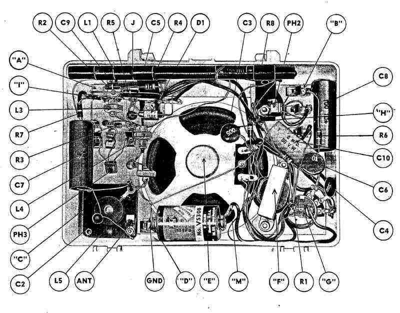
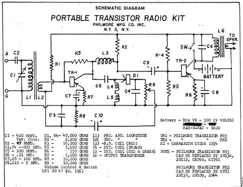
This is a U.S. made kit available around
1957. Note the transistors are connected by Fahenstock clips in the chassis
diagram. At this stage of transistor development, there was a fear of damage
soldering them into circuit from the heat. It seems Philmore thought it
best to avoid any risk from inexperienced constructors in this regard.
Although the circuit has only two transistors, it is more complex than
the the "Boys Radio" type of design. Resistance coupling is used between
TR-1 and TR-2, and choke L3 is the RF load for TR-1.
L4 and L5 are interesting. Looking at
the chassis diagram, they are ordinary Litz wire honeycomb wound RF chokes,
as is L3. It would appear that L4 and L5 might be different values, each
with a different resonant frequency, so as to even out the gain across
the band. No regeneration is provided, but the ferrite loopstick is longer
than the small pocket sets, and an external aerial connection is provided
for. TR-1 is certainly well stabilised with a 1K emitter resistor. As well
as this, R3 provides further stabilisation, being shunt fed from the collector.
The audio output stage is completely standard.
Knight Kit.
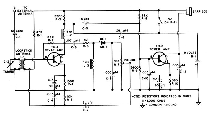
Also from the late 1950's, this was produced by the well known kit manufacturer, Knight Kit. The circuit is remarkably similar to the Philmore, but is for earphone use only.
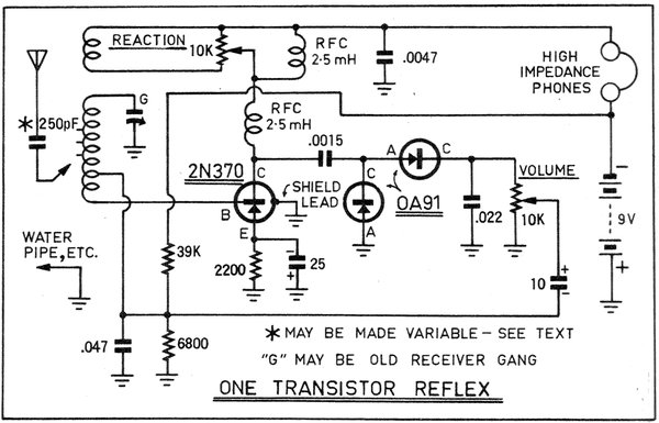
This one transistor receiver was described in Radio, Television & Hobbies for June 1963. Unusually, it uses an air cored aerial coil, although details were given how to use a ferrite loopstick. It also has separate volume and regeneration controls, which, strictly speaking, is the better way to do things. The circuit can be operated at maximum selectivity in areas of high signal strength, and the volume reduced as necessary. It was claimed that full headphone reception of local stations could be obtained in a suburban location with no aerial and earth connected, using only the air cored coil.
In August 1963, a one transistor amplifier was described for speaker operation. See here for more details on this receiver.
The Mellotone is fairly mediocre with no regeneration. The 5kW commercials can be heard enough to know that they're there, but certainly not entertainment value. The ABC stations can be heard clearly, but not at any great volume. It should be pointed out that this set still has the original electrolytic capacitors which could be faulty.
The two transistor Denshi circuit
gives good earphone volume from the two 50kW ABC transmitters on just the
ferrite rod aerial, and 3LO on 774Kc/s from Melbourne could faintly be
heard at night, but nothing else above about 800Kc/s unless the outdoor
long wire aerial was very lightly coupled. It appears the gain rolls off
until up around 1500Kc/s when a few distant stations could again be heard.
Perhaps the value of the RF choke has something to do with this.
It should be quite satisfactory however,
in the intended service area for the 5kW commercial stations.
The three transistor Denshi circuit
is a huge improvement. One the ferrite rod alone, the ABC transmitters
easily drive the speaker to full volume, which mounted in the well baffled
'console' is actually quite loud. The 5kW commercials are all receivable,
but not with any great volume. At night some distant stations are
receivable. With the volume control modified as previously described, I
experimented with regeneration. This was achieved by placing a small capacitance
between the RF transistor collector and the tapping towards the top of
the aerial coil. The capacitance was less than 5pF. With only the ferrite
rod, plenty of distant stations could be heard at entertainment level.
The audio transformers in the Denshi kit seem to be quite good and provide
better frequency response than those used in the homemade Crown.
The Walkie performs very well on
the ABC transmitters; 576kHz, 630kHz, 702kHz, but the gain drops off towards
the 1600kHz end of the band. It's quite possible a small amount of regeneration
would improve this. The extra audio transistor makes a difference, giving
a very loud signal on the ABC stations.
Improvements to the reflex design would be to use a ferrite loopstick which is as long as possible, and to use resistance coupled audio stages for better sound quality. This would require a third transistor to make up for lost gain. Adjustable regeneration is essential for maximum sensitivity. This need not complicate the operation for non technical users, since it can be incorporated with the volume control. As the receiver is not loaded with an external aerial, selectivity does not suffer unacceptably with less than full regeneration.
There is no doubt that obtaining loudspeaker reception with no external aerial, and just two transistors is an impressive achievement.