T092 package at left used for ZN414Z, YS414,MK414 and TA7642. T018 package at right is used for the original ZN414.
T092 package at left used for ZN414Z, YS414,MK414 and TA7642. T018
package at right is used for the original ZN414.
History of the ZN414.
From the mid 1970's onwards, if you wanted
to build a simple AM radio, chances are the circuit you would use was based
around the ZN414.
The design of this TRF radio IC, well
known to European and Australasian constructors of radio receivers, was
commenced in November 1970 by Ferranti in the UK. It was designed using
new Collector Diffusion Isolation techniques, originally developed by the
Bell Laboratories. A prototype was working in July 1971.
Originally, it came in a TO18 package, like a BC108 transistor, but the last of the IC's were made in a T092 plastic case, as the ZN414Z. There are only three connections; input from a ferrite rod aerial, earth and audio output. The circuit is a TRF type with all gain at the received frequency. The IC also incorporates a detector and AGC circuit. Supply is a nominal 1.5V at 300uA and audio output is sufficient to drive a crystal earphone. Needless to say, it became very popular for matchbox size radios in the 1970's. So popular was the ZN414 in the UK, that it eventually killed off the one and two transistor reflex circuits which used to regularly appear in their constructional magazines. No doubt, Clive Sinclair would have been delighted if such an IC was around when his key ring Micromatic (two transistor AM reflex) receiver was being developed.
Eventually, Ferranti went the way of many
semiconductor companies, and the ZN414/ZN415/ZN416 were no longer being
produced. However, all was not lost as the Asian manufacturers had cloned
it under a number of different types. First was the YS414 and then came
the MK484, LMF501T, TA7642, and various other xx7642 types. The MK484 and
TA7642 are now the most common types.
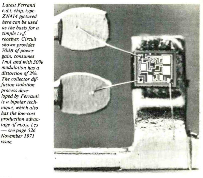
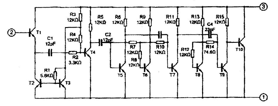
From Wireless World, January 1973, this shows the inside of the
ZN414.
The first magazine project to use the ZN414 was in Practical Wireless, January 1973. This was a receiver built as a key ring radio, and used the ZN414 in its most basic form. Output was used to drive a crystal earphone directly. The battery was a mercury button cell.
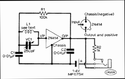
Circuit from PW, January 1973 is the most basic possible.
Subsequently, in February 1973, Practical Electronics described a full size loudspeaking portable set, the "P.E. Triffid". This article contains an interesting history regarding the design of the ZN414, and was compiled by an employee of Ferranti who was involved with the design. Therefore, anyone working with the ZN414 would be wise to read this article several times and take note of the points brought up.
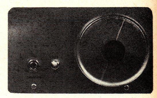
Electronics Australia, May 1974.
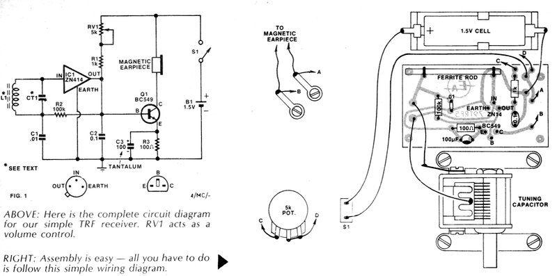
In Australia, the first project description
of a ZN414 receiver was in Electronics Australia, May 1974. It drove low
impedance headphones via a transformer.
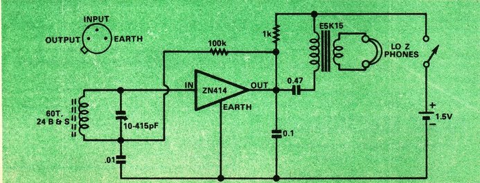
Note that a fixed 1K resistor is shown as the load for the ZN414. The article pointed out that some adjustment might be required. The transformer is a valve output type 5K to 15 ohms.
Electronics Australia, August 1979.
Then in August 1979, Electronics Australia
presented a circuit driving a low impedance earphone via a transistor.
For this design, the load resistor has now been made variable. In the following
issue was a two transistor audio amplifier add on.
Electronics Australia, July 1985
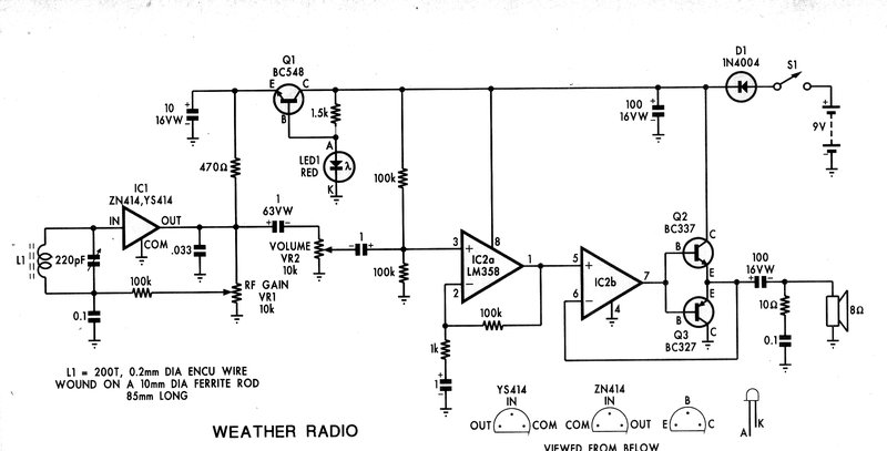
Next in line for EA's ZN414 projects was
a receiver designed for long wave weather beacons, operating around 370Kc/s.
The ZN414 circuit is conventional, but the audio amplifier is excessively
complicated. One wonders why the op-amp was bothered with - they could
have used an LM386 instead and dispensed with the four extra transistors.
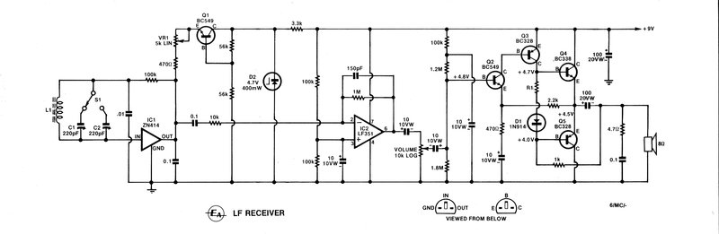
Electronics Australia "Weather Radio" from July 1985.
Electronics Australia, February 1986.
Performance breakthrough!
This project called the "AM3" was presented
by Technicraft, a small supplier of mostly radio based kits in the mid
1980's. It seems that for the first time, someone had actually examined
the limitations of the IC, and its AGC system with strong signals, and
done something about it. The circuit was an instant success when I tried
it, and all subsequent ZN414 circuits in Electronics Australia (September
1987 - Switched tuned receiver in cassette box [note this particular circuit
has the 100K shunting the aerial coil - bad design]), and Silicon Chip
(September 1994 -Weather Radio) have used it. Surprisingly, outside Electronics
Australia and Silicon Chip readers, the new circuit is still unknown, and
the rest of the world battles on with the limitations of the original circuit
oblivious to the improvement possible. Having said that, the original circuit
is acceptable provided you're not in a strong signal area.
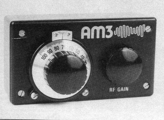
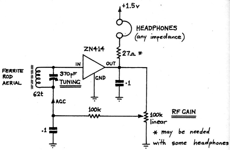
The AM3 receiver at left. At right is the basic circuit with full
control of the AGC. The load resistance is now no longer critical.
The modification provides the greatest possible range of control, and one benefit was that the load resistor was now no longer critical. It can be seen that the bias fed into the ZN414 input is fully adjustable from zero volts to the voltage at the output terminal. The value of the potentiometer is not critical and can be between 10K and 100K.
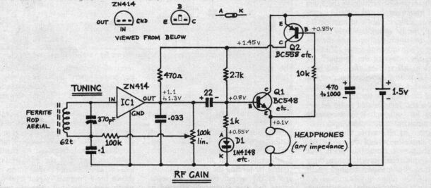
The full AM3 circuit. Q1 is an emitter follower to drive the headphones.
Q2 is the power switch that detects whether or not the headphones are plugged
in. D1 is for temperature stabilisation.
Unfortunately, the TA7642 does not work effectively with this method of gain control. The TA7642 is not an identical ZN414 clone, and this is discussed further on.
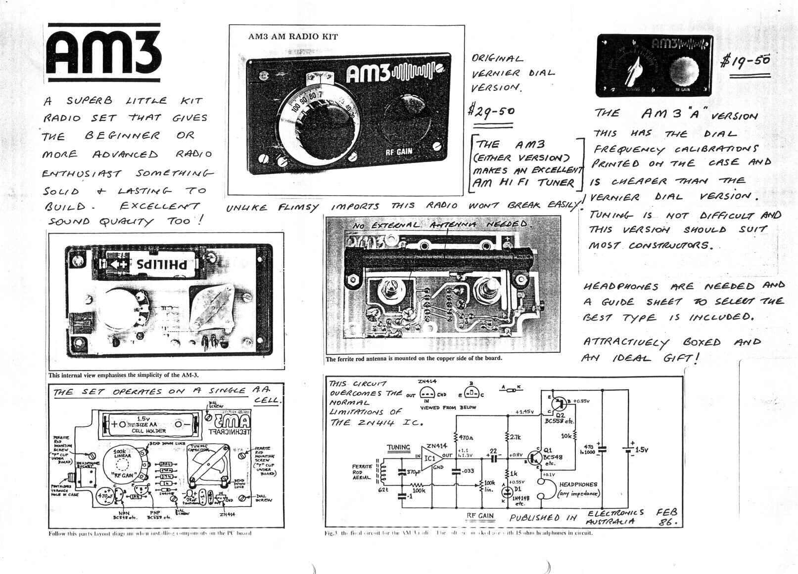
From the 1986 Technicraft catalog.
Postscript March 2025: I was contacted by Steve Payor, who along with the founder of Technicraft, David Whitby, designed this set. Steve provided photos of the prototype which are shown below.
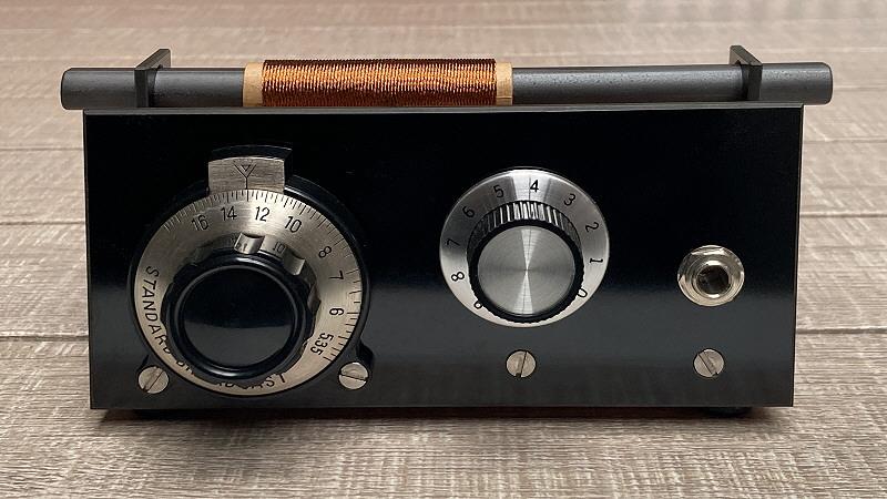
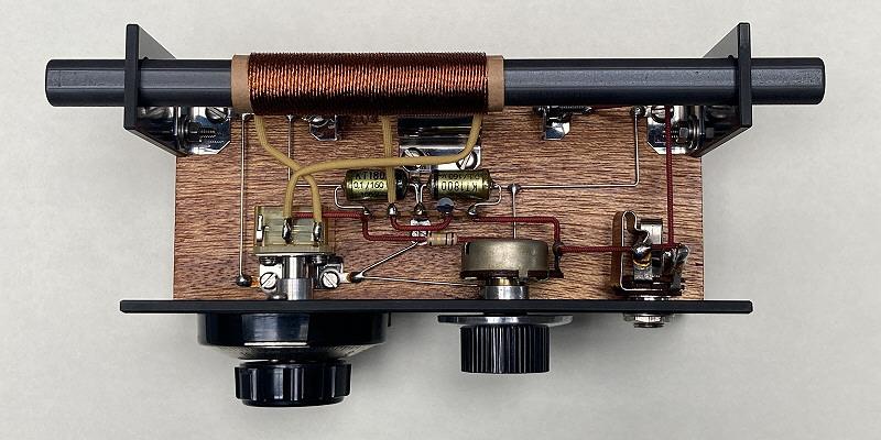
Prototype of the AM3.
As you can see, it's a work of art, but importantly has a proper ground plane to ensure maximum stabilty for the ZN414. Similarly, the PCB for the kit version was also carefully designed, to prevent coupling to the ferrite rod from the ZN414's supply current. Remember, the ZN414 has a lot of gain in the one package, and less than ideal layout will prevent optimum results being obtained. This is something to keep in mind with solderless breadboard constructions and the like.
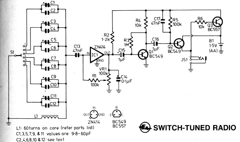
Electronics Australia, September
1987
This design was a switch tuned radio designed
to fit into a cassette case. It uses the new improved gain control circuit.
Unfortunately, the designer has made the mistake of connecting the 100K
resistor so it shunts the tuned circuit. While the DC conditions will be
correct, the aerial coil now has reduced Q and selectivity suffers. The
method of biassing the output transistor is extremely crude, and unlikely
to give optimum results.
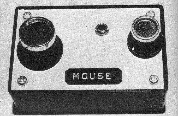
Easy Electronics, Number 1, "Mouse"
This short lived Australian magazine from
1976 described a ZN414 receiver with one transistor driving an earphone.
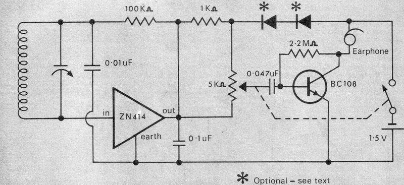
As can be imagined by the high value of bias resistor for the BC108, it was intended to drive a high impedance magnetic earphone. The resistor would need to be reduced for lower impedance phones, and a collector load resistor provided if a crystal earphone was used. The two diodes are not given a type number, but are merely described as "signal diodes". One could assume they are germanium types such as 0A91. Two silicon types would stop the circuit working. These diodes were recommended if there were signs of instability, and simply reduce the supply voltage.
Funway 1 "Beer Powered Radio"
In 1980, Dick Smith Electronics had first
published their "Funway Into Electronics" series of project books. There
were three volumes, with the first containing a series of projects built
on a piece of chipboard. Subsequent volumes described more complex projects
built on printed circuit boards.
In Volume 1, project 14 describes a beer
powered radio. The idea is that beer performs as the electrolyte of a simple
battery. Interestingly, with the "beer battery", no load resistor is used
with the ZN414; presumably the internal resistance of the battery is sufficient.
An option was shown to power the radio
off a normal 9V battery. Here we see something different. Instead of a
1.5V regulator, the load resistor is simply increased to 33K to allow 9V
operation. The technique certainly appears to work, and the cheap commercially
made radios of today, operating off 3V, use the same technique - see the
Future Kit further down.
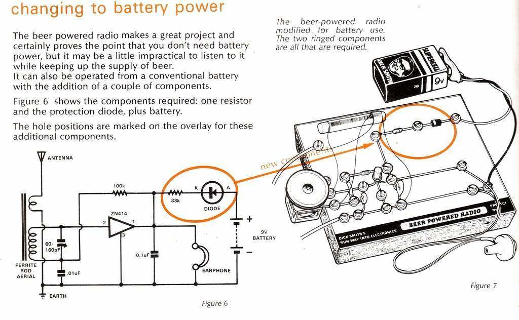
Operating a ZN414 off 9V is shown in project 14 of Funway Into Electronics.
The earphone is a crystal type.
Funway 2 "Pocket Transistor Radio".
In "Funway Into Electronics", Volume 2,
was the "Pocket Transistor Radio" which drove an 8 ohm magnetic earphone
and ran off a 9V battery. Its performance was very poor for two reasons.
Firstly, the method of obtaining the supply for the ZN414 was a bodge and
resulted in instability, and secondly, the 9V battery pressed up against
the ferrite rod ruined the signal pickup. This particular circuit was the
same as EA's August 1979 design, except for the 9V modification. This was
actually my first experience with the ZN414. Back in 1981 when I built
this kit, I had very little idea what was going on, so merely followed
the instructions and built up the radio as described.
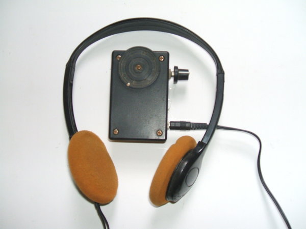
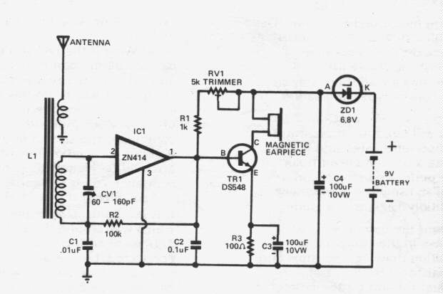
At left is my version with decent headphones. At right is the circuit
of the Funway 2 radio circuit. Unfortunately, it's a bodge and performance
is poor.
Apart from the zener diode and 9V battery,
the circuit is conventional and commonly used. The ZN414 is connected as
per the data sheet. Output at pin 1 then feeds a DS548 (BC548) transistor
as a class A earphone driver. TR1 bias comes from the voltage at pin pin
1 as its DC coupled. Collector current will therefore depend on the setting
of the 5K pot, signal strength, and R3. Current is [Vpin1 - .6]/100.
C3 reduces audio degeneration and loss
of gain. I have seen some circuits on the internet which are similar, but
the transistor base is AC coupled and biassed with a single resistor from
the collector. The emitter resistor retained in these circuits is pointless,
(unless it is unbypassed for reducing audio gain) as there is no resistor
from base to ground. It's amazing how many badly designed circuits abound
on the internet and other places.
Having assembled the kit, performance was unacceptable. It had terrible instability and low volume. Back then, I didn't understand zener diodes and thought the power supply was a bit strange. I did know the ZN414 was meant to run on 1.5V, however. So, I tried powering it off an AA cell instead and that immediately cleared up the instability. My suspicion was right; something strange with the 9V battery and the zener diode. In retrospect, there's two faults with the design. As it is, there will actually be 2.2V across C4, not 1.5V. And this will be even higher with a new 9V battery. Definitely outside the ZN414 ratings! Assuming we got the correct 1.5V across C4 by using a 7.5V zener diode instead, there are still two remaining deficiencies. First, it's incredibly wasteful. Given the cost of 9V batteries, 5/6 of what you're paying for is going up as heat from the zener diode, and contributing nothing. Five out of the six cells are effectively being wasted. The second fault is that battery life will be much less than when a single 1.5V cell is used to power the circuit. Why is this so? As we know, battery voltage starts dropping as soon as we start using it. As a rule of thumb, something designed for a 9V battery should work down to about 7.5V, giving an acceptable life. If we apply that principle here, we will see that it won't take long for this kind of drop in battery voltage to kill off the supply altogether. Yet, the individual cells in the 9V battery would still be capable of powering the radio directly.
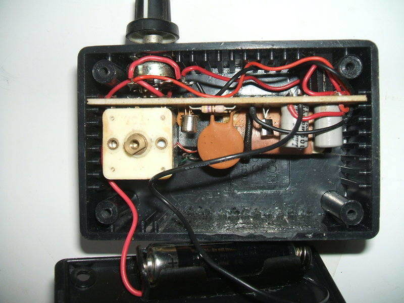
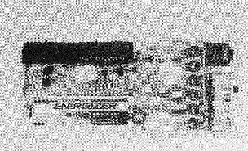
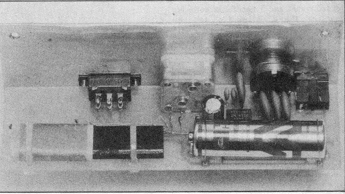
Inside the set with AAA cell fitted. The ZN414 is visible next to
the tuning condenser.
The reason for this bodge? Back in 1980,
Dick Smith did not sell single AA or AAA battery holders, and a 9V battery
was the only type with a connector that would fit in the preferred box.
The 9V battery approach could have actually
been done to advantage. Firstly, the ZN414 should have been powered as
per the Hobby Electronics circuit (see below), with a series resistor and
shunt regulator diodes. The 9V battery will last a very long time with
this configuration; probably longer than if one of the individual cells
was used directly. Secondly, the full 9V could have been used for the audio
stage, and with a transformer to match the earphone impedance. Alternatively,
a crystal earphone could have been used, with a considerable reduction
in current consumption. Either way, this would provide more gain and volume.
For my version of this project, I eventually
installed a AAA battery, of which the holder only just fits the box. The
low volume was, not surprisingly, a result of an 8R earphone being provided
with the kit.
As I dislike those white low impedance
earphones provided with transistor radios up until the 1980's, I installed
a 3.5mm stereo socket for proper 32R Walkman headphones. Most ZN414 circuits
that use these recommend the earphones be connected in series to increase
the impedance to 64R instead of 16R, which is what you'd get connecting
them in parallel. While the higher impedance allows greater volume, the
problem is that the two transducers are out of phase, giving a peculiar
and unnatural sound. I prefer the correct in phase connection instead,
despite loss of gain. It is true that you could connect them in series
and in phase by cutting off the plug and accessing the individual transducer
connections.
I have a few sets of these headphones,
but two of which I discovered are of higher impedance (about 250R per transducer).
These are the headphones provided in aircraft for passenger use. With a
set of my Qantas headphones plugged in, this receiver really became alive
with good volume and excellent bass response. With normal 32R headphones,
the Sydney stations were just audible 80km from their transmitters, but
with the 250R units, volume became acceptable. Near the centre of Sydney,
about 10km from the transmitters, there is more than enough volume on all
stations. A big improvement was had with lower impedance (~32R) headphones,
by including a .01uF capacitor from the DS548 collector to earth. Without
this, the lower impedance load caused instability before the gain control
could be set to the optimum position.
Incidentally, the current consumption is around 22mA with the low impedance phones - hardly suitable for the carbon zinc 216 9V battery originally specified! An improvement would be to self bias the transistor, and isolate its base with a capacitor.
The other modification I did to the kit
was replace the 5K trim pot with a panel mounted switch pot. This gives
a good range of adjustment for the AGC. DSE's idea of only needing to set
the pot once shows how unfamiliar the kit designer was with the ZN414.
Additionally, the 1K resistor was reduced to 470R as this is the value
shown in the data sheets, and 1K just did not allow full performance to
be attained. Maybe ZN414's are not all the same, and some would have been
satisfactory with 1K.
The performance of this radio has been
drastically improved with these mods. Even in Sydney a few km from the
5kW transmitters at Homebush, I can receive some interstate stations at
night, including 2XL, 2GN, and 2AY. The old 1224 2WS transmitter (now 2RPH)
at Prospect can now be received without interference from 1170 2CH or 1269
2SM.
Interestingly, this design has been copied
by a U.S. based kit supplier, complete with zener diode bodge.
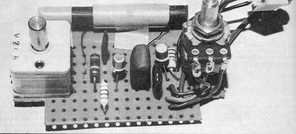
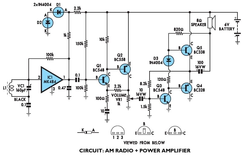
Hobby Electronics, July 1981.
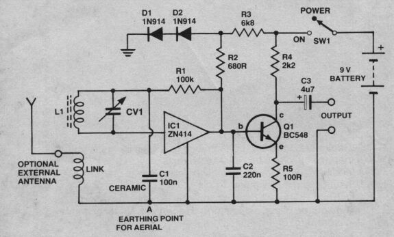
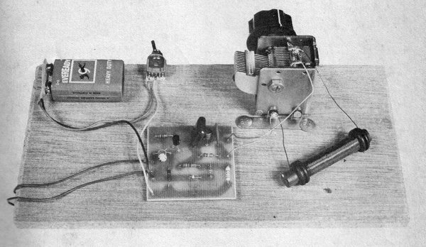
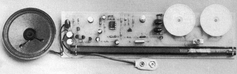
This circuit is from one of ETI's spin offs; Hobby Electronics,
July 1981. This is the one shown
here in the prototype photo. It can receive interstate stations at
night with no external aerial or earth. The only limit to performance is
the quality of the tuned circuit. Note the method used to obtain the 1.4V
supply. My unit actually uses a YS414.
Electronics Today International,
March 1987.
In the 1980's, two more versions of the
IC appeared in an 8pin DIL package. These were the ZN415 and ZN416 and
were simply a ZN414 with an audio stage capable of driving low impedance
headphones. No doubt these versions were developed as the Walkman style
of headphones were now in vogue. Apart from being much more comfortable,
the sound quality and hygiene aspects far surpass the single magnetic or
crystal earphones which until now had been standard with transistor radios.
This article described a kit sold by Dick Smith, and is the only magazine
project I have seen in Australia using the ZN415.
It looks like Ferranti had no intention of making Ragc adjustable. However, one could alter the supply voltage instead. If the resistor needed to be reduced, one could parallel an external resistor between pins 6 and 2. The IC would also be adaptable to the Technicraft method of gain control by ignoring pin 8, connecting C1 instead to the pot wiper. The gain control would be fed from pin 2.
Silicon Chip, September 1994, "Weather Radio".
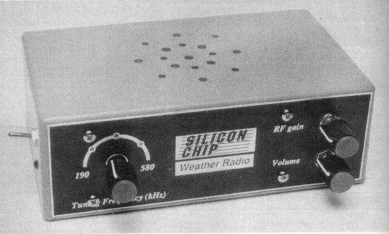
The connection between Silicon Chip and Electronics Australia is evident, with this design using the Technicraft method of gain control. The overall design is better than EA's "Weather Radio" but the lack of bias for the output transistors is not something I'm keen on. Admittedly, the design was meant for voice only. The ZN414 output bypass being only .033uF is curious.
Silicon Chip, January 2012, "Build an AM Radio".
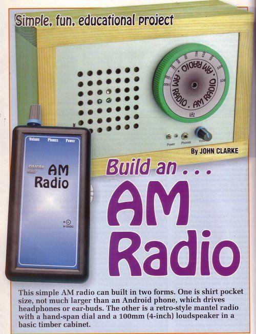
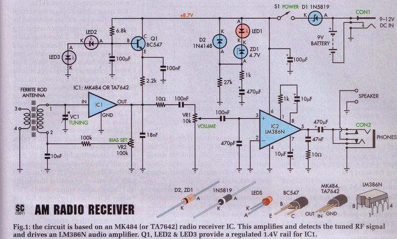
This design again uses the Technicraft
method of gain control. However, in this instance the control is preset.
Unfortunately, this will prevent the best performance being obtained as
the receiver is tuned across the band. I would recommend a conventional
potentiometer accessible to the user instead. The .018uF capacitor on the
MK484 output is much lower than the recommended .1uF, and this could cause
problems with stability. The 10R resistor would be superfluous and have
no effect on anything. LED2 & LED3 are actually infra red types, simply
used for voltage stabilisation. LED1 is a power on and battery condition
indicator.
It is interesting to note that Silicon
Chip also found the selectivity of the TA7642 inferior to the MK484. See
notes further down.
Future Kit MK484 kit.
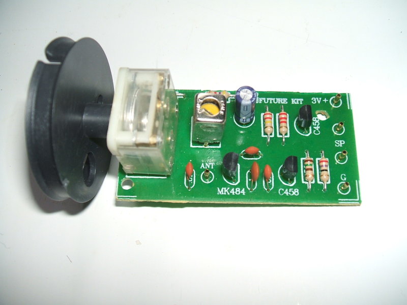
This was bought on ebay from "Future Kit"
in Thailand. The circuit is largely conventional, with the main difference
being the use of an oscillator coil instead of the usual ferrite loopstick.
This makes for a very compact receiver, but a short wire aerial is required.
To operate from 3V, the MK484 load resistor is 4.7K. Unfortunately, there
is no provision to adjust this, so performance may not be optimum. In the
example I bought, the receiver was unstable at 3V, but worked quite well
at 1.5V.
There is a mistake in the circuit diagram
in that there is a 150R emitter resistor for TR1, which has not been shown.
The "speaker" supplied is not a speaker as shown on the above diagram,
but one of those awful earbuds. 2SC458's are used for the transistors,
but one could use BC548's or similar if duplicating the circuit. The IC
supplied with the kit as purchased was a TA7642.
It is interesting to note that transistor
MW coils have been standardised for some time. Red is usually the oscillator
coil, and yellow designates one of the IF transformers. As can be seen,
the coil supplied is yellow. As it turned out the inductance of this coil
could not cover the entire broadcast band. The inductance is insufficient.
With maximum tuning capacitance, the lowest receivable frequency was 920Kc/s,
with the trimmer fully closed. The upper limit was around 2Mc/s. With the
oscillator section paralleled, the range was 760Kc/s to 1950Kc/s.
The receiver works better with a ferrite
loopstick aerial with the correct inductance.
See my construction of the kit here.
The quality of Future Kit designs seems to be questionable, as this FM receiver shows.
Note the mistake with the 100uF capacitor's polarity.
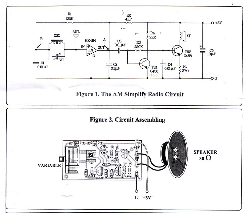
This circuit is from the Jaycar "Short
Circuits" series of project books. These replaced the old Dick Smith "Funway"
series, and follow the same format. The MK484 receiver shown here is Project
20 in Volume 1. There are several aspects of the design which could be
improved upon. Firstly, again we see the 100k resistor connected directly
between input and output pins of the MK484. The tuned circuit is thus damped
with 100k, and the advantages of the high input impedance of the MK484
are lost. The resistor should of course be connected between the output
pin and the earthy connection of the coil.
Secondly, there is no adjustment for the
operating conditions of the MK484. At the very least, a 5k pot should be
connected in series with the 1k load resistor. This in itself might also
require reducing to 470 ohms, to get the proper range of adjustment.
Thirdly, the bypass capacitor at the output
pin is very high and will result in a reduction of audio bandwidth. The
data specifies 0.1uF. The 0.1uF at the earthy end of the coil is probably
satisfactory, although the data specifies 0.01uF. I have not built this
circuit, but would expect it to have a fairly high audio gain.
The circuit as drawn also contains a mistake.
The 100uF coupling capacitor for the speaker is shown with the polarity
reversed. The emitters of Q4 and Q5 will be about +3V above earth, and
with the speaker connected as shown, there will be +6V at what is shown
as the negative terminal of the capacitor. In reality, the capacitor being
reverse biassed by only 3V is not going to make it explode or anything
like that. The resistance of the speaker voice coil will limit any damaging
current. What will probably happen is that a higher than normal DC current
will flow through Q4 and the speaker voice coil for a while, until the
capacitor reforms with reverse polarity.
The LM372.
Prior to the ZN414, the U.S, National
Semiconductor company had developed their LM372 in the late 60's. This
IC was rather obscure and seemed to disappear very quickly.
Functionally, this is a very similar IC
to the ZN414. However, it has a low input impedance, requiring a tapping
on the aerial coil when used for a TRF receiver, and runs off a higher
supply voltage. The LM372 has a gain of about 60dB (slightly less than
the ZN414), is in a different package, and has more of its internal circuitry
available to the outside world. It was intended to be used as an IF amplifier/detector,
but Electronics Australia published a TRF circuit with it operating in
the broadcast band, fed from a ferrite rod aerial, as one would with a
ZN414. A later project saw it used in a 27Mc/s superhet remote control
receiver.
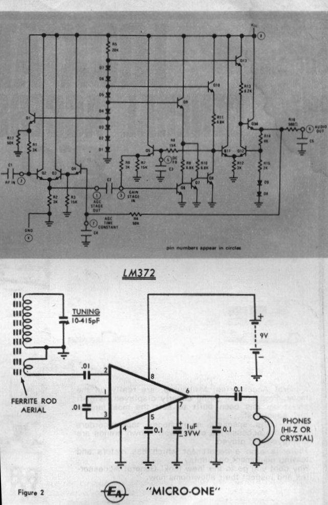
Was National Semiconductor's LM372 a source of inspiration for Ferranti?
This circuit was described in Electronics Australia, April 1969.
For those interested in the LM372, Hugo Holden did a rather elaborate recreation of the EA project, which was presented in Silicon Chip for February 2025.
Wireless World TRF design.
An interestingly possible source of inspiration
for Ferranti to design the ZN414 was a circuit published in Wireless World
for October 1966, and presented locally by Electronics Australia the following
month. This used a chain of directly coupled transistors fed from an aerial
coil. If one incorporated an emitter follower input circuit to provide
the necessary high input impedance, and replaced the diode with a transistor
detector, the circuit would become rather similar to the internal workings
of the ZN414.
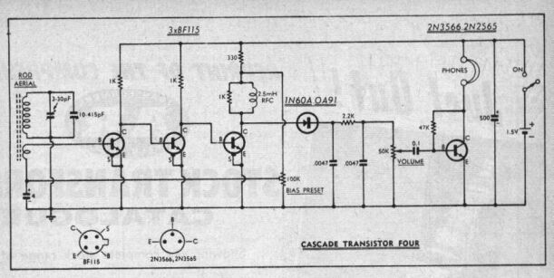
This circuit, originally from Wireless World, October 1966, and
shown here in an article from Electronics Australia, November 1966, bears
more of a resemblance to the internal workings of the ZN414, and also works
from 1.5V. This circuit has been tested and works well. An extra
transistor will give good volume into an 8 ohm speaker.
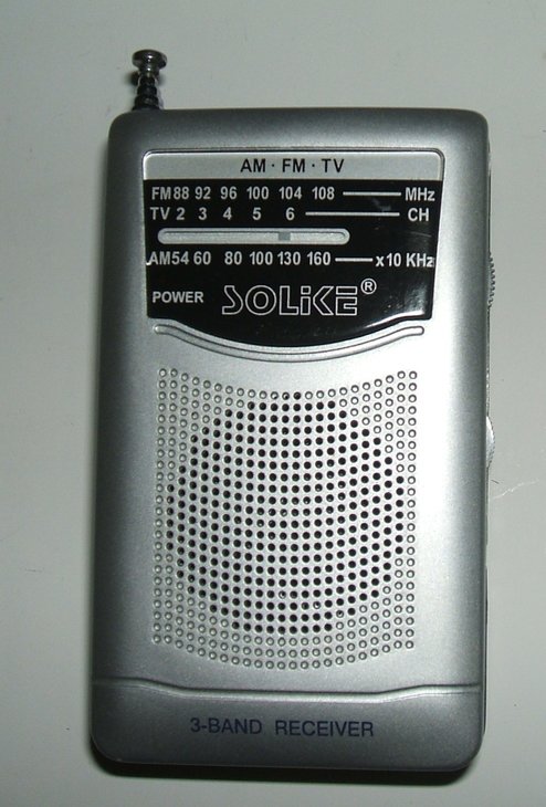
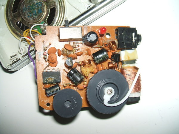
This cheap pocket AM/FM radio uses a TA7642. It can be seen to the
upper right of the 8 pin audio IC. With such a small ferrite loopstick
sensitivity is poor.
About the ZN414 and its clones.
At this point it is worthwhile downloading the data sheets. Search for data on not just the ZN414, but the other clones as well.
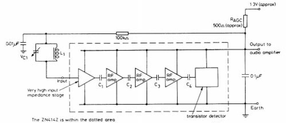
Basic connections for the ZN414. This is the "bare minimum" circuit.
The power supply is one of the most attractive features for portable or miniature receivers. Only one 1.5V cell is required, and in its most basic form driving a crystal or high impedance earphone, current consumption is only 300uA. This makes operation from even the smallest cell possible. Voltage is however critical and Ragc may need to be changed for best results. Typically, 500R to 1.5K are shown on most circuits. Various stabilised and adjustable supplies are shown on the data sheets for use when the receiver needs to be powered from other sources; e.g. 9V. Note that the Ferranti application circuit shown above uses a 1.3V supply - this suggests they had intended the ZN414 to operate from a single mercury cell.
The official operating frequency of the
ZN414 and clones is 150Kc/s to 3Mc/s. From articles in the English magazine,
"Radio and Electronics Constructor", it appears the gain falls off in the
longwave band. It was recommended only if Radio 2 (BBC long wave transmitter
in the UK) gave a good signal in the area where the radio was to be used.
However, both Electronics Australia (July 1985) and Silicon Chip (September
1994) described radios for the reception of the long wave weather beacons
located at various Australian airports. This, and my own experiments seem
to infer the ZN414 does a good job below the broadcast band.
As for the upper frequency limit, while
3Mc/s is the official cut off, many stories exist of reception higher into
the SW bands, up to around 6 Mc/s. This cannot be guaranteed, and would
be dependent on individual IC's and signal strength.
Of course, it doesn't have to be an aerial
coil that feeds the input of the ZN414; it can just as well be the secondary
of an IF transformer. This means that by using the ZN414 as an IF amplifier/detector,
normal superhet techniques can be used to cover frequencies well outside
the 150Kc/s-3Mc/s band. Examples are given in the data sheets on how to
do this.
There are also circuits with regeneration
applied. Given that the RF bypassing at the output pin is not perfect,
some of the RF can be fed back into another winding on the aerial coil.
Other circuits show an external Q multiplier.
My use of the ZN414.
For years I had seen the ZN414 circuit
from EA May 1974 in the back of the Dick Smith catalog, and the ads for
the device proclaimed such virtues as "equivalent to a ten transistor radio".
Ten transistors it may have, but it actually has only four stages of RF
amplification. This is about the practical limit before instability would
set in. The other transistors are used for the detector, AGC, impedance
matching, and stabilisation. I had also seen the ZN414 project in the August
79 issue of Electronics Australia.
My first experience with it was with the
Funway circuits in 1981. The "Funway 2" circuit was a failure as previously
described, but the beer powered radio operating off 9V seemed OK. I then
forgot about it until the mid 80's when I was learning about solid state.
I experimented with many different ZN414 circuits and associated audio
amplifiers. I used to demonstrate to some of my fellow college students
a ZN414 receiver with a two transistor amplifier driving a speaker that
I'd build on a breadboard from time to time. Soon after, I went off
listening to AM as a result of changes to formats and stations migrating
to FM. So, the ZN414 became dormant in my designs until later, now that
I'm mainly listening to AM again.
Also was the fact I'd accumulated a few
of the $2 shop radios using the ZN414 clones.
My interest was rekindled when Dick Smith
Electronics was selling MK484's at half price, just before they closed
all their electronics stores. I went and stocked up with a lifetime
supply, knowing that at the time they were getting out of components retailing.
Later on, with cheap TA7642's on ebay, I stocked up on those too.
Selectivity.
Being a TRF circuit with selectivity determined
only by the one tuned circuit, sound quality is excellent. It is certainly
up to the standard for feeding into a hi fi amplifier and decent speaker
system. As I've said elsewhere on the site, if people heard wideband AM
through a good sound system, it wouldn't have the poor reputation it has
unjustly suffered.
However, this and the limited AGC can
be a problem in strong signal areas. Here, selectivity becomes poor. When
I was still living in Sydney not too far from the transmitters, I had difficulty
receiving 2WS on 1224 as it was a weak western suburbs station. The problem
was 1170 2CH and 1269 2SM being much more powerful in my area. So, a DX
receiver it was not! Nevertheless, I did try the Funway 2 receiver in a
car and bus with good results.
The problem was the AGC system cannot
cope with strong signals. One can of course attenuate them by using a smaller
ferrite rod (compromise) or by turning the receiver away from the interfering
stations (may not be convenient). At home in the mid Blue Mountains, about
70km away from the AM transmitters at Homebush, performance is very good
with selectivity about the same as a valve TRF set. I can receive 2LT (Lithgow)
without any interference from 2GB(Sydney) and yet the stations are only
27Kc/s apart. At night, the usual interstate stations are received.
Many designs allowed the supply voltage
to be adjustable, as this is actually quite critical and has a large effect
on receiver performance. This was done either by making Ragc partially
variable or by adjusting the supply to the usual fixed Ragc. This helped,
but wasn't as good as the breakthrough developed by Technicraft, in their
article printed in Electronics Australia for February 1986, described above.
While the MK484 is still available, it appears this is old stock. It is more expensive than the TA7642. At some point tests will be done to see if it is possible to find suitable operating conditions for the TA7642 to make it perform as well as the ZN414.
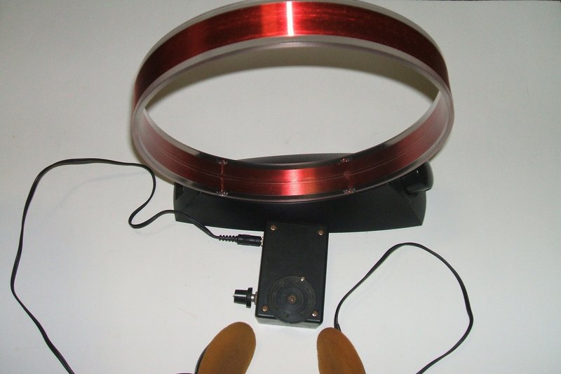
Tuned loop aerial provides spectacular performance.