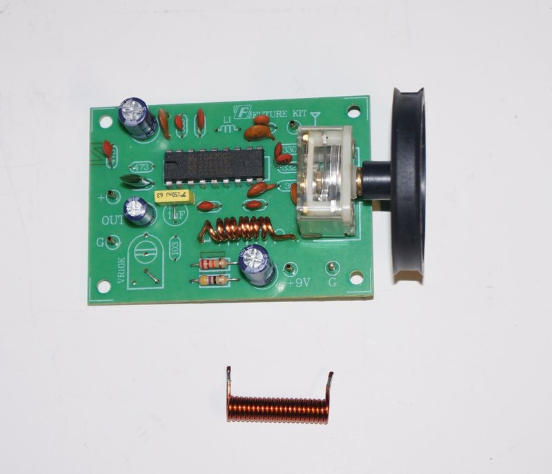
Shown with oscillator coil as provided with the kit. PCB has been modified as described in the article.
Shown with oscillator coil as provided with the kit. PCB has been
modified as described in the article.
This kit from the Thai "Future Kit" establishment
is sold under the interesting name of "FM Simplify Tuner 88-108MHz" and
the catalog number is FK707. Based around a TDA7000, and inexpensively
available on eBay, I decided to purchase one.
For those not familiar with the TDA7000,
it is described further here.
The design was interesting to say the
least. Upon examining the parts, my attention was caught by two things.
Firstly, the oscillator coil had far too many turns to operate in the FM
band. Secondly, an IC socket was included - something very undesirable
for use at VHF.
I assembled the kit, without the IC socket,
or the preset volume control trimpot. The inclusion of that seemed supefluous,
as any amplifier used with the tuner will have a proper volume control.
Adjusting a PC mounted trimpot with a screwdriver for the volume is hardly
practical.
Since the trimpot was not required, C15
becomes superfluous as C13 already provides DC isolation.
The performance of the tuner was awful
with poor senstivity and difficult tuning. Suspicious of the oscillator
coil, I suspected it was oscillating out of band, and sure enough looking
on the spectrum analyser confirmed this.
Suddenly, I realised just what the designer
had done. With the TDA7000, the oscillator runs at virtually the same frequency
as the received station. This is because of the very low IF; 70KHz. This
'adaptation' resulted in the oscillator running at one third of the frequency
it was intened to. The mixer was operating by virtue of the third harmonic.
That is, the fundamental oscillator frequency was 29.3 - 36MHz.
One possible reason for doing this is that a 30MHz tuned circuit is much less critical than one operating at 100MHz. Alignment would in theory be easier, and in fact with enough variation in the tuning capacitance, probably not necessary. Ironically, the use of an IC socket would also have little effect at the lower frequency; the only VHF part now being the mixer input. As I found, the story didn't quite end there.
The Circuit.
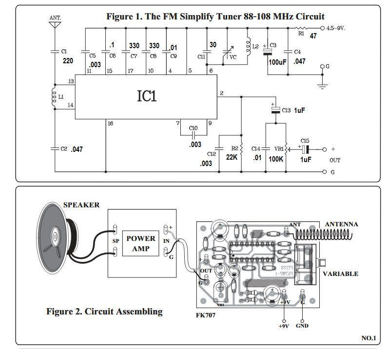
First we'll have a look at the circuit
as presented. There's a few strange things. Starting at the supply, the
inclusion of the 47R resistor seems pointless. Why would you want to increase
the source resistance of the power supply? It then transpired that there
is actually a 100uF across the supply input on the PCB.
VC is the local oscillator section of
a MW tuning capacitor, a popular choice with TDA7000 circuits. However,
there is no series capacitor to lower the maximum capacitance - this of
course because of the lower oscillator frequency in this circuit.
The aerial input is non standard, being
fed directly into one side of the mixer via a 220pF. Usual procedure is
two capacitors across the input coil with the aerial connected to their
junction.
The inclusion of C14 seems odd, and undesirable.
It is effectively in parallel with C12, making the total de-emphasis capacitance
.013uF instead of the recommended .0018uF. Therefore, I left out C14.
VR1 is marked as 10K on the PCB and is
what is supplied, despite the circuit showing 100K. The use of 10K would
upset the de-emphasis circuit and loads the TDA7000 more than is desirable.
C12, stated to be 0.003uF, was actually
0.01uF.
Fixing the Problems.
Obviously, trying to use the third harmonic
from the oscillator was not the correct way to use the TDA7000 and the
tuner was just not usable. First thing was to try to get the oscillator
working at 88-108MHz. I wound up a couple of likely looking coils and one
of them tuned covered the FM band. The 30pF across the tuning capacitor
had to be removed of course, and even the the minimum capacitance is still
too high for a favourable L-C ratio. So, a 47pF was connected in series
with the variable capacitor. Now it was oscillating where it should, from
84MHz to 113MHz, which was ideal.
Performance was still far from what a
TDA7000 should perform like. Upon looking closely, it turned out other
things had been done to get the IC working with the lower local oscillator
frequency.
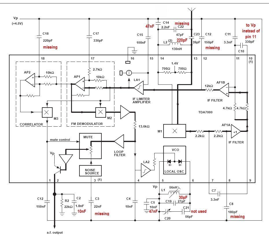
Block diagram from the Philips application notes. The alterations
are labelled in red. Note the component designations are not the same as
the Future Kit.
The missing capacitors were installed, which required drilling holes in the PCB and running the component leads to the appropriate pads. Of course, the layout wasn't optimum, but it was better than simply tacking parts all over the track side of the board.
By far, this is the worst performing TDA7000
receiver I have tested. Reception becomes noisy at around 35uV. Despite
the low cost and attractive look, it is best avoided. Indeed the "Simplify"
in the kit's name is appropriate - it seems the designer has removed every
part possible before the circuit actually stops working altogether. The
design of the PCB does not follow the recommended design, which is important
for VHF. Using the third harmonic of the local oscillator was never intended
by Philips, and could be one reason why the muting circuit had to be disabled.
Make sure any TDA7000 receiver kit you
obtain is properly designed.
My intention is to transfer the parts
to a correctly designed PCB and use a ferrite cored oscillator coil.
There is another similar kit, FK715, which uses a TDA7088T. Although the TDA7088T is designed for auto scan tuning, it can be used with a variable capacitor, and the FK715 uses it this way. The oscillator coil looks the same as in the TDA7000 kit, which suggests it's also operating on the 3rd harmonic. Also, the TDA7088T is mounted on a plug in header board for ease of construction but this results in an unsuitable PCB layout.
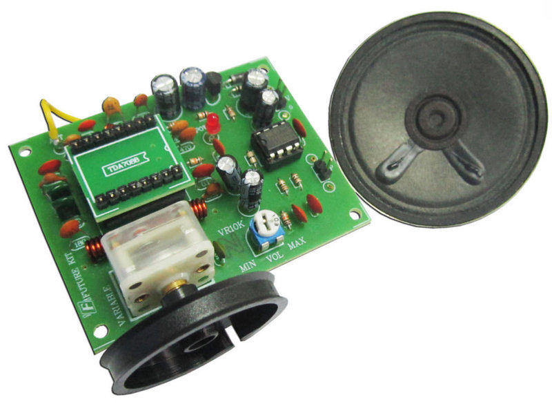
This kit uses the surface mount TDA7088T. It would suffer the same
problems as the TDA7000 kit. Note the larger than normal oscillator coil.