My attention was first drawn to this IC when the Australian edition of Elektor, in December 1983, published a project called "Personal FM". European editions presented it in September 1983. Then in the late 1980's, Tandy were selling this IC for about $12. I didn't really take much notice of it until around that time when I was looking for simple VHF FM receiver designs, that would function better than super regen circuits. (This was before I discovered the Pulse Counting receiver design). I dug out the Elektor article and was intrigued at how this IC functioned and the lack of coils and alignment usually associated with superhet receivers. Looking at the Philips data with its mention of 1.5uV sensitivity also got my attention.

The December 1983 issue of Elektor was my introduction to the TDA7000.
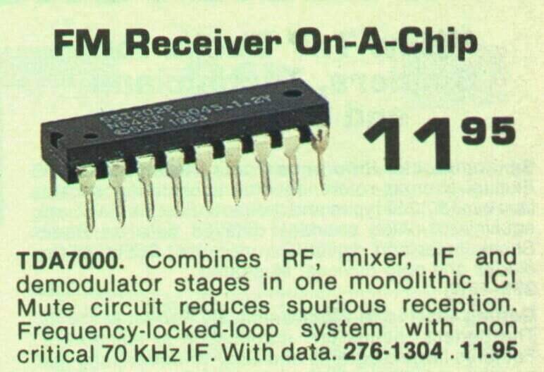
Taken from the 1989 Tandy catalog.
Background
The TDA7000 was
patented by Philips in 1977 but was not announced until January 1983. There's
some interesting information regarding the history in
this article.
What is unusual about this IC is how it
operates. It is a proper FM superhet receiver, with the usual local oscillator,
mixer, IF amplifier, limiter, and phase detector. The difference is that
there's only one tuned circuit; the local oscillator. The TDA7000 relies
on a low IF so that ordinary Op Amp circuitry can take care of the gain
and bandpass characteristics. The use of a low IF in an FM receiver is
not new, and dates back to the valve pulse
counting receiver design. The convenient aspect of this is that ordinary
'audio' circuitry used for the IF amplifier is non-critical, no alignment
is required, and there are no inductances or ceramic filters. Pulse counting
receivers have used an IF of around 200KHz which can accomodate the +/-
75KHz deviation of the FM signal comfortably.
Philips decided against this type of design,
because it would be seen as confusing for non-technical users, since a
200kHz or thereabouts IF creates two tuning points. Equal reception will
be obtained with the local oscillator 200kHz below the receiving frequency,
or 200kHz above it.
The TDA7000 has an IF of only 70KHz to
avoid this characteristic. However, this will not accomodate a fully modulated
signal without sounding rather distorted. So, how does it work with a 70KHz
IF?
It's quite simple, in that there is what
Philips call a Frequency Locked Loop. Basically, the local oscillator is
shifted in response to detector output so that the bandwidth of the mixer
output is never more than +/- 15KHz. It is effectively compressing the
frequency deviation of the modulated signal.
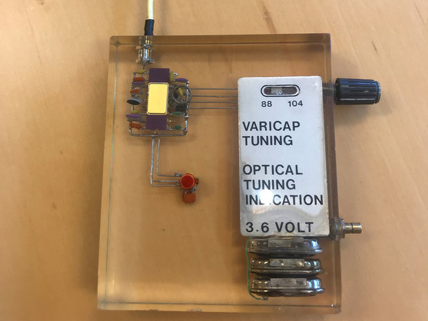
Original prototype TDA7000 receiver encapsulated in resin, powered
from three NiCd cells. It has tuning indication (see application notes).
This version does not use the RF input bandpass filter.
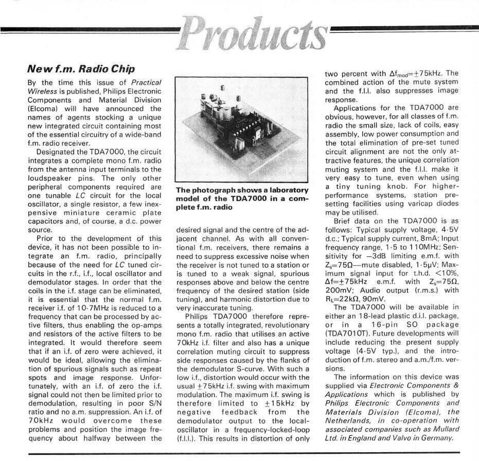
From Wireless World, June 1983. Note the error regarding the output
level; it should be 70mV, not 70mA.
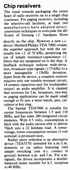
From Practical Wireless, Augist 1983.
The muting or squelch feature is novel
to say the least. Its purpose is to prevent signals being heard if the
receiver is mis-tuned. This is because reception can occur at more than
one tuning point, and the user may not be aware that the receiver is not
tuned to the correct one, with inferior reception being the result. Although
as far as the user is concerned, it performs like any other muting circuit
does, but the TDA7000 provides an artificial noise generator, so that the
receiver still sounds alive while tuned off station. In this regard, it
tunes like a 'normal' FM receiver, with the white noise present until a
station is (correctly) tuned in.
The muting circuit is based around the
correlator. The limited IF signal is inverted and delayed half a cycle.
This is compared to the incoming IF, and if it is the same, the muting
circuit allows the audio through. If the signal is random noise, or the
receiver is mistuned, the IF signal and its delayed half cycle will not
be the same. The muting is then activated, and the audio output is fed
with white noise.
If the artificial noise is not required,
remove the .022uF condenser at pin 3. The muting can be disabled by connecting
a 10K resistor from the supply to pin 1. This may be desirable for very
weak signals.
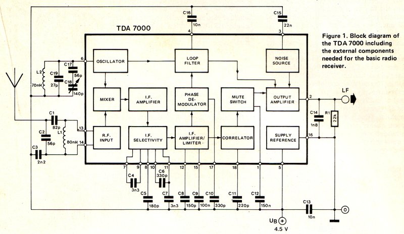
Block diagram of the TDA7000 as used for a typical FM receiver.
Audio output is around 75mv.
Stereo Simulation.
The TDA7000 is not suitable for stereo
reception, since the detected bandwidth is insufficient to acommodate the
53kHz stereo signal. However, later types TDA7020T and TDA7021T were
stereo compatible.
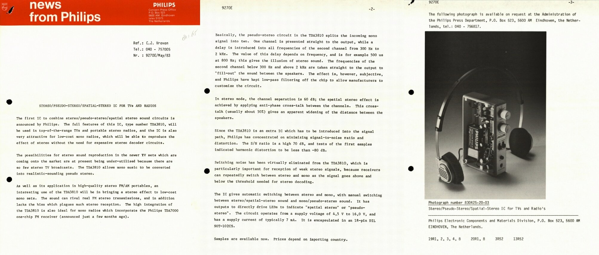
My attention was drawn by a reader to
the TDA3810 stereo simulator IC.This was announced by Philips around the
same time as the TDA7000. The TDA3810 simulates stereo from a mono signal,
or can simulate increased channel separation from a stereo signal.
In simple terms, this is done by delaying
the 300Hz to 2kHz component of the input signal to create a second channel.
The technique has been around in one form or another since the valve era,
but was never popular until portable stereo radio cassette recorders made
their appearance in the 1970's. Various magazine projects also published
designs for such adaptors, and these were based around discreet components,
and/or simple op-amp IC's. The point of interest here is that the TDA3810
release notes specifically mention use with the TDA7000. A point worth
noting is that while the TDA3810 does not recreate the original stereo
signal, it does have the advantage of eliminating the poor signal to noise
ratio that FM radio suffers from, when receiving weak stereo signals.
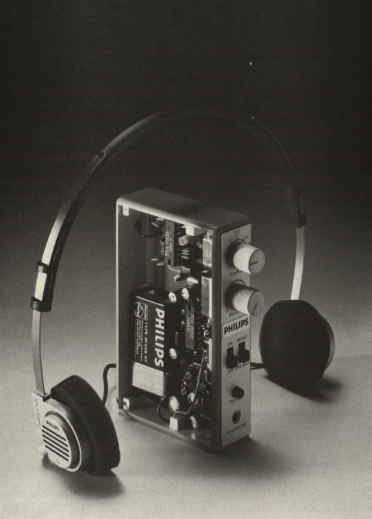
Prototype TDA7000 receiver with TDA3810 stereo simulator.
Philips created a receiver shown above, containing a TDA7000 and TDA3810. It is a very elegant design, but unfortunately appears to be just a one off proof of concept prototype. One cannot help but note the similarity of this receiver with the Elektor design. In fact, there may actually be a connection, because Elektor mentioned the possibility of simulated stereo in their TDA7000 receiver project article. Subsequently, in the European editions at least, the TDA3810 is presented in a project to convert the TDA7000 receiver to "psuedo stereo". The Philips receiver shown above was also shown in the article, but no mention was made of its availability.
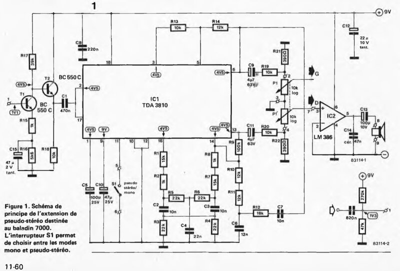
The TDA7000 provides simulated stereo with this add on circuit.
Of course, an additional LM386 is required for the newly created audio
channel.
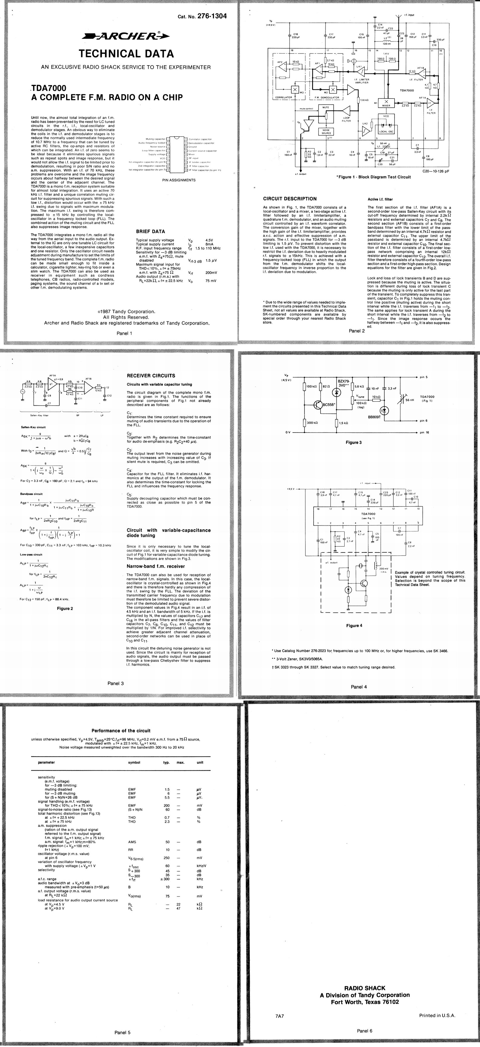
At this point I recommend reading the Philips application notes, AN192.pdf, followed by the data given by Philips Components. They give a good background to the design and use of this IC. For curiosity value, have a look at AN193.pdf for the application notes regarding Narrow Band FM. In case you were thinking a low IF would be suitable for a NBFM receiver, you're right. Apparently, the TDA7000 is not suitable for stereo, although I have seen one circuit where the output was fed into an LM1310 stereo decoder. It is not known how good the channel separation was.
As Philips (now NXP) considers this IC obsolete, any links to the application notes on their site no longer work, but these are provided below:
The TDA7000
starts a family!
Philips didn't stop with just the TDA7000
in its 18pin DIP package. Next came the TDA7010T which is the surface mount
version. It comes in a 16pin SMD package. What of the other two pins? Well,
the artificial noise generator has been dispensed with and so has the connection
to one of the IF filter capacitors. The latter is a bit odd; I'm not sure
if it could be dispensed with altogether or if they managed to fit it inside
the chip. The data for both chips is the same apart from that.
R.I.P.
TDA7000
The TDA7000 is no longer being produced
by Philips, having being withdrawn from manufacture, December 2003. Actually,
it's a pretty long production run when you consider it was produced for
20 years, and it's taken nearly another 20 years for stocks to start drying
up. So, if you want to play around with this IC, keep in mind that there
won't be any new stock from Philips. The last TDA7000's I bought were made
in 1994. As DIP gives away to SMD packaging, it is unlikely it will
ever be cloned by Asian manufacturers. There are stocks of the IC still
available, through the likes of eBay and Ali Express, but their price can
be quite variable, so shop around. It should be possible to get them for
less than $7.00 each. WES Components in Sydney still has them listed in
early 2025.
The SMD versions, TDA7010T, TDA7020T,
and TDA7088T were kept in production for a bit longer, but these too are
now out of production.
However, there are Asian produced clones
of the TDA7088T in current production. These are identifiable by '088'
in the number, but a different prefix; e.g., CD9088, SC1088, etc. While
these are mostly used with push button auto search tuning, ordinary variable
capacitor tuning can be used instead. The only catch therefore for the
home constructor, is that they're SMD. These '088' IC's are prevalent in
small inexpensive radios found in $2 shops, and appear in various eBay
kits. Some are auto scan FM only, some use a variable capacitor, and where
AM reception is included, a TA7642 (ZN414 clone) circuit is used.
**Fake TDA7000's.**
A reader has drawn my attention to fake
TDA7000's. I assumed the possibility was always there, since Philips ceased
production, and some of the prices offered from Asian sources seem very
good. It has finally been confirmed. In my collection of TDA7000's, one
has been confirmed as fake. There is solder residue on the pins, and what
looks like flux down one side of the IC. Importantly, the resistance between
pin 5(+) and pin 16 (-1) is greater than 2M. A real TDA7000 shows around
500k. This was from a batch bought from Ali Express.
The possibility of a 'reclaimed' TDA7000
is suspicious in itself, since it was used in so few commercially made
items. More than likely, the IC with solder residue was simply re-labelled.
The helpful reader also indicated that if the labelling was done by laser,
it too was a fake.
Reverse Engineered TDA7000.
Another reader drew my attention to a
fascinating article by Ken Shirriff, who has reverse engineered the TDA7000.
This is the most extensive analysis of this IC that I have seen.
Constructing
a TDA7000 receiver
I bought my first TDA7000 IC in 1988 and
tried to build up a receiver on a piece of matrix board. Here I learnt
the first thing of importance. Layout and groundplanes are critical to
using this IC. The Philips data gives a PCB layout and this should not
be altered too much. Of course, my matrix board receiver didn't work properly.
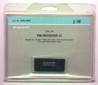
Bought from Tandy in the Sydney suburb of Chatswood. Like all their
components, packaging was excessive. An abbreviated reprint of the Philips
AN192 application notes was included.
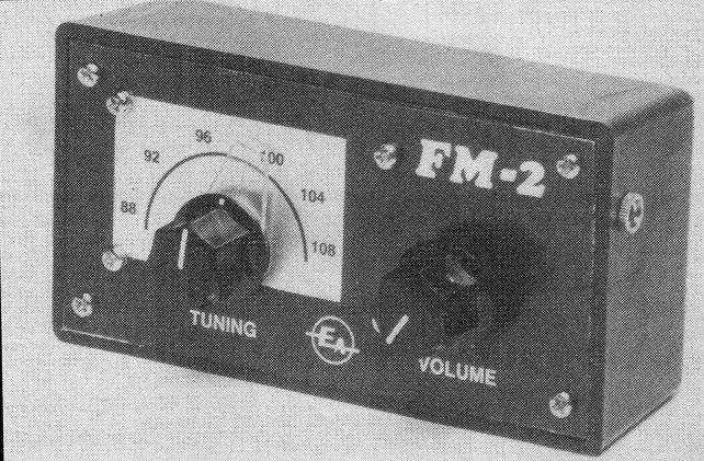
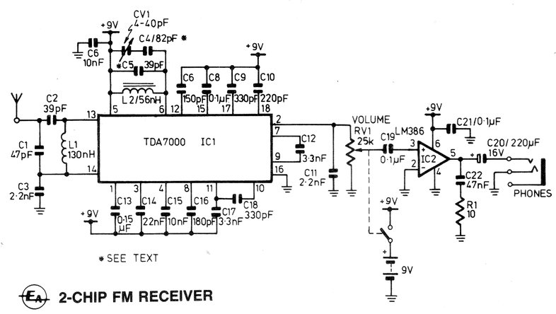
This is my adaptation of the EA circuit.
This receiver certainly worked and was a good introduction to the TDA7000.
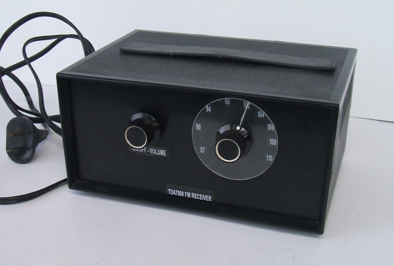
TDA7000 receiver works from 240V mains.
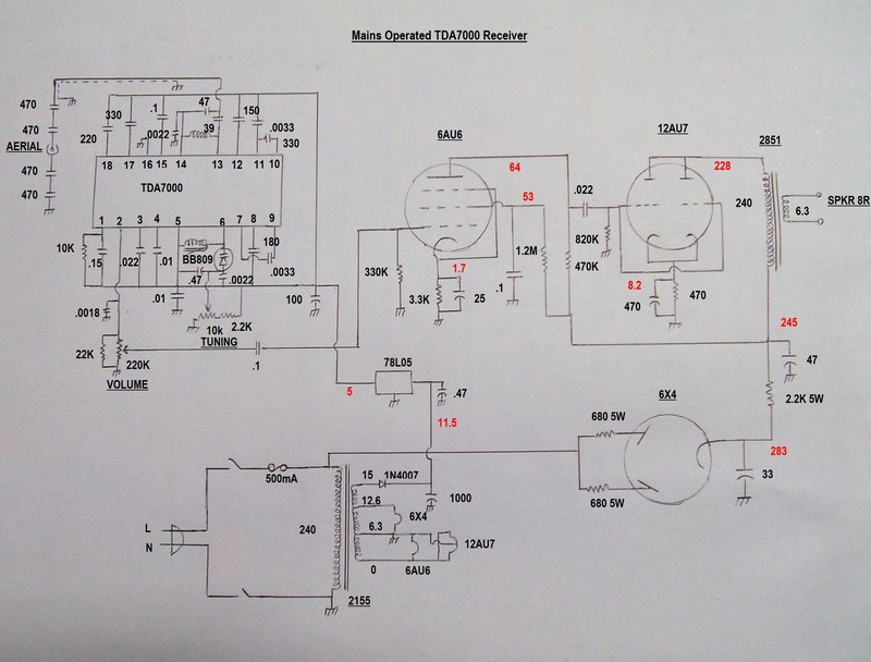
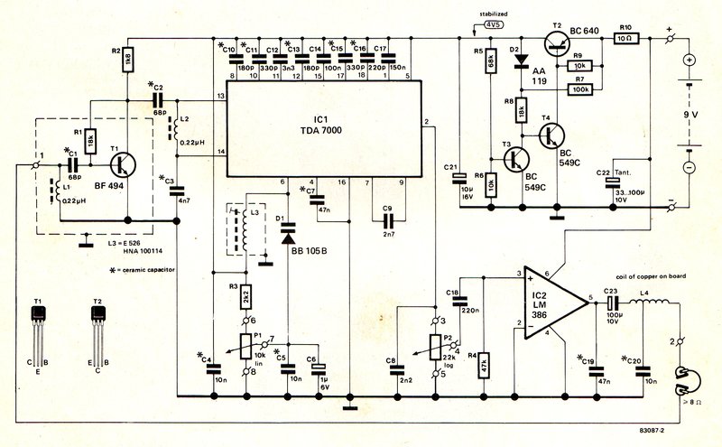
Circuit of the mains operated receiver.
Project was presented as a bare PCB construction. Speaker is small
and unbaffled, which prevents optimum sound quality being obtained.
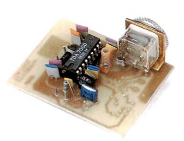
The receiver shown above was acquired around
2017 as a half built kit. I completed it as per the orignal magazine design,
but included the noise generator capacitor at pin 3. Ignoring the sound
quality from the small unbaffled speaker, performance is otherwise excellent.
It is a very attractive unit with the
open construction, allowing one to admire the TDA7000 IC in its full glory,
especially as the one in this particular kit has the Philips logo. The
PCB design is correct, which allows full performance from the TDA7000.
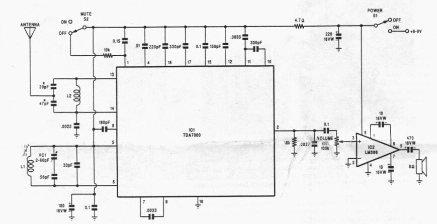
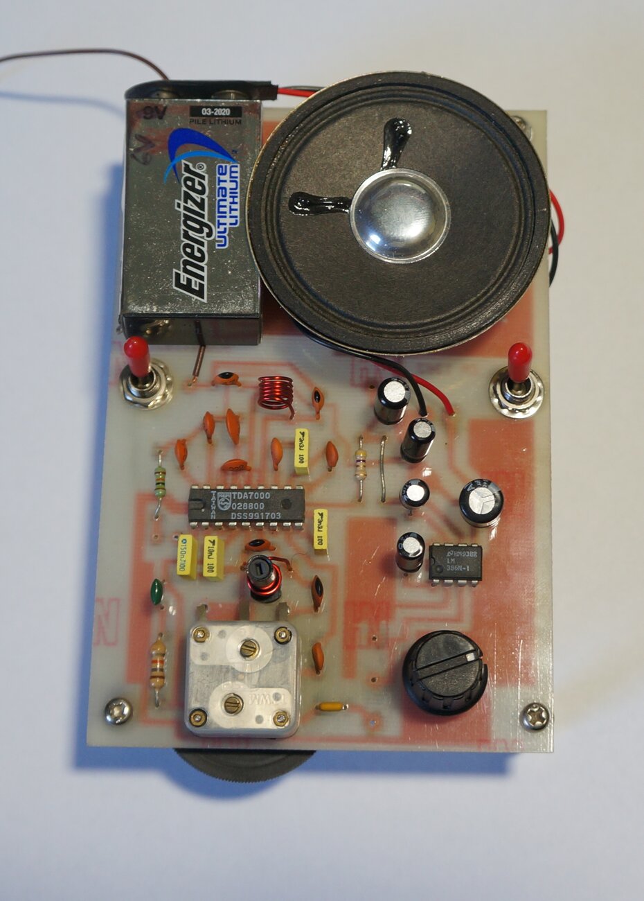
Circuit of the Silicon Chip receiver. I connected a .022uF capacitor
between pin 3 and the positive rail to enable the noise generator.
The circuit is very typical using an LM386 for the audio stage. Note that the artificial noise capacitor at pin 3 is not included in this circuit. When the "mute" switch is on, the receiver is silent between stations. If the capacitor is included, a slight rushing sound is heard when the squelch is activated.
Back in 1995, I built one of these kits in a plastic box with speaker, but wanting to make it smaller, I built a new enclosure out of aluminium, with a Lexan cover. (January 2004). I didn't bother including the speaker as I seldom used it. However, once I'd done this, the performance seemed very poor. Sensitivity was really bad. Eventually I noticed that it seemed like some sort of spurious oscillation was going on. Bridging the negative battery terminal straight to the case brought up a huge improvement, and a permanent cure was made by connecting the PCB groundplane to the chassis directly, not just relying on the headphone socket. It just goes to show how finicky things are at VHF.
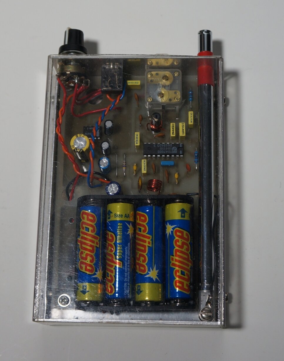
I mounted 4xAA cells on the PCB where Silicon Chip intended the
speaker to be placed. The squelch switch was not used; instead the squelch
is permanently disabled. The telescopic aerial extends to 75cm, which is
a quarter wavelength.
In this construction, the squelch is permanently disabled. As such, there is no point including the noise generator capacitor.
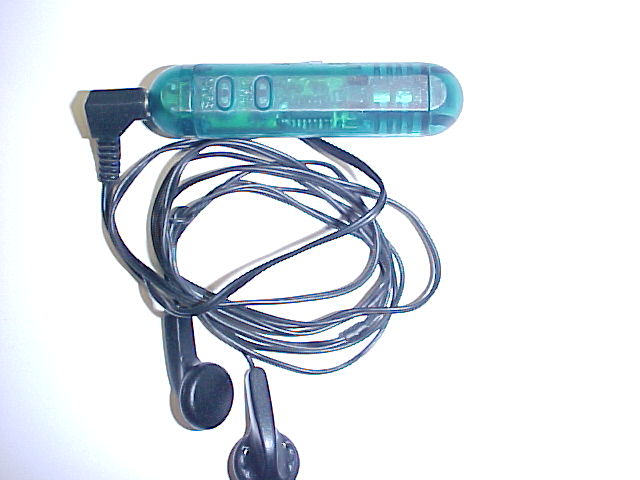
Those earphones are awful.
This tiny receiver is not much bigger than
an AA cell. It is powered off two LR44 button cells, which are expensive
and I assume wouldn't last terribly long. I'll be on the lookout for LR44's
at the markets and $2 shops now that I've got this radio! As with all these
sorts of radios, the headphone lead functions as the aerial. Supplied with
this receiver were a pair of those awful "in-the-ear" type of miniature
type earphones. Apart from the appalling sound quality, they are insensitive,
unhygenic and dirty, fragile, and do not block out external sounds. So,
I use the normal kind of headphones instead.
The enclosure is all clipped together,
and once I'd opened it, sure enough, a TDA7088T was visible.
The audio amp appears to be one transistor;
ie. single ended class A. I don't know what current it's drawing so I can't
say whether it's consuming much more battery current than a class B amp
would. In any case I would prefer AAA cells rather than the LR44's.
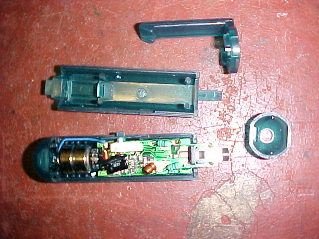
Opened up, this shows two LR44 cells, the switch and headphone socket.
Note the two RF chokes to allow the headphones lead to be used as the aerial.
The TDA7088T is on the other side of the PCB.
The power switch is a minature slide switch
on the side, which has an extra position for volume. This is obviously
done to avoid a space consuming potentiometer. So, we have only two levels
of volume; full and something a bit less.
How well does it work? Quite well actually.
Performance is the same as the TDA7000 IC in terms of sensitivity and sound
quality. However, the TDA7088 has the mute permanently enabled so some
weaker stations that could otherwise be received with a TDA7000 or TDA7010T
cannot be received on the TDA7088T. Also, the headphone lead aerial is
not as efficient as a 75cm telescopic aerial so this needs to be taken
into account.
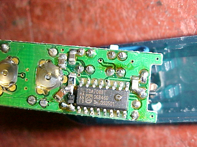
Close up of the TDA7088T. The scan and reset switches are to the
left.
The scanning circuit works very well, there
is virtually no waiting for the radio to find the next occupied frequency.
Once you have reached the 108Mc/s limit, you have to press "reset" to get
back to the 88Mc/s end of the band. It does not automatically do this like
a PLL type of circuit would.
These TDA7088 receivers are very common
in $2 shops (look for the "scan" & "reset" buttons), and you certainly
shouldn't pay more than $5 for one. Most of them use the Chinese clone
of the TDA7088; the SC1088. More often than not, these cheap auto scan
FM receivers also incorporate a torch. Some also incorporate an AM receiver.
This invariably uses a TRF circuit based around an MK484 (ZN414). Variable
condenser tuning is used with these sets, on both AM and FM. Unfortunately,
AM sensitivity is poor because of the very small ferrite loopstick aerial.
They're a strictly "local station only" affair as far as AM goes. Sound
quality is good, however, as there is only one tuned circuit (i.e. the
ferrite loopstick).
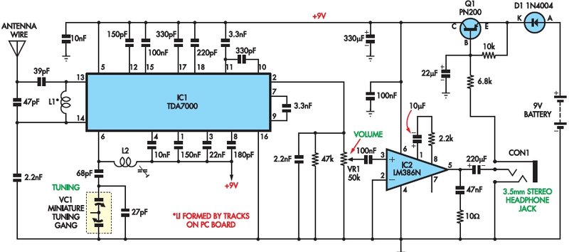
The design is elegant, fitting into a small
low profile plastic case. There is no power switch as such, but instead
the DC resistance of the headphones is used to bias on Q1, which is in
series with the 9V supply. I'm not too keen on the out-of-phase connection
of the earphones. Wired in series like that gives a peculiar unnatural
sound. However, the way the socket is wired means that if a mono plug is
inserted, everything works correctly. The right channel socket contact
is already earthed, so inserting a mono plug does not short circuit the
output as would normally happen. The power switch also works normally,
as the 6.8K resistor is taken directly to earth. Despite that, the instructions
imply the use of stereo earphones. The aerial is a 75cm length of wire.
Further work needs to be done on this
receiver. It is not working as it should. The squelch constantly cuts in
and out on anything but very strong stations.
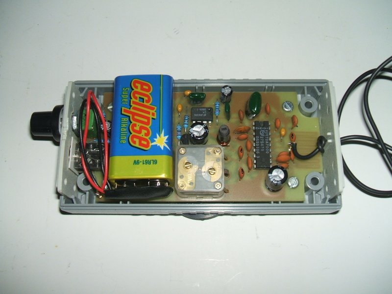
Like a lot of TDA7000 receivers, a miniature
tuning condenser is used, of the type intended for MW transistor radios.
Normally the lower capacitance oscillator section is used with a series
capacitor, but in this circuit the oscillator section is in series with
the higher capacitance aerial section. This means the capacitor shaft is
floating at RF and cannot be earthed. A plastic knob must be used. Despite
this, there does not seem to be a problem with hand capacitance.
Improvements for this receiver would be
to disable the squelch, rewire the earphone socket, and earth the tuning
capacitor shaft.
Unfortunately, this kit has now been discontinued,
but I purchased some of the last in stock just in time.
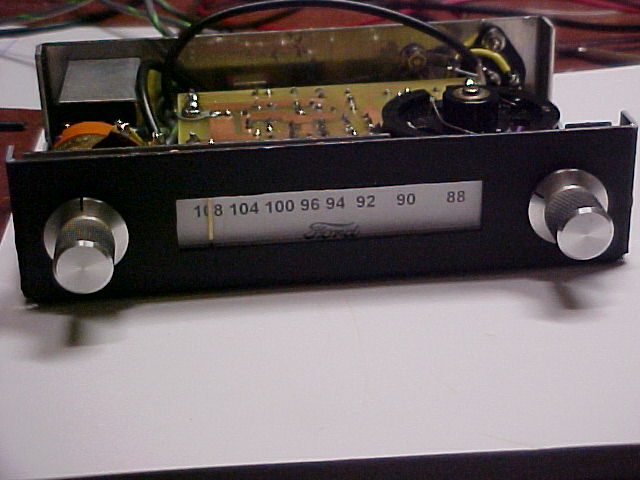
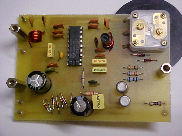
Under dash tuning head.
For my first version of the radio used in my Model T Ford, I built a tuning head using a TDA7000. I designed and etched the PCB, based on that shown in the Philips application notes.
The radio consisted of a tuning head mounted
under the dash in the usual position, and a valve amplifier with power
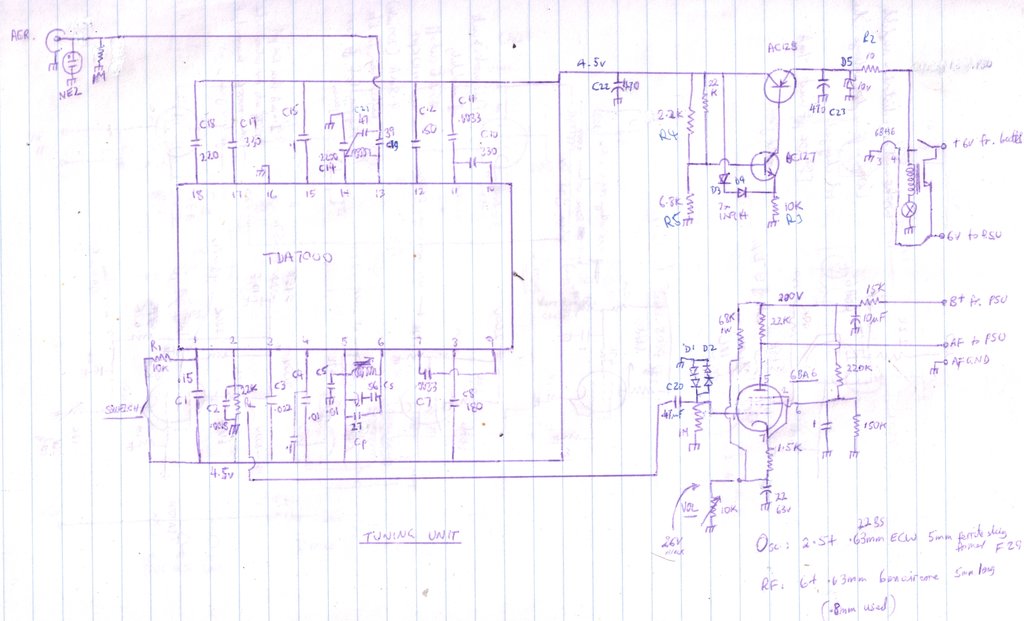
supply under the front seat. The circuit shown is the prototype tuning
head. There wasn't enough room to include the 6BA6, so it was located in
the amplifier box. It was subsequently replaced with a 6CS6 which better
suited the method of volume control.
The TDA7000 circuit is as per the application
notes, but with a few additions to make it suitable for automotive use.
The car 6V supply is regulated to 4.5V with a two transistor and two diode
regulator. A 10V zener clamps any spikes on the car supply. The aerial
input is protected with a neon lamp and static discharge resistor. Note
the four diodes at the 6BA6 grid. These were included to protect the TDA7000
in case of an internal short in the 6BA6 or other fault which might allow
high voltage to be applied to the TDA7000 audio output. The diodes clamp
to 1.2V which is greater than the audio signal.
Performance of the TDA7000 in this set
is the best I have yet encountered. It goes to show the correct PCB layout
makes a difference.
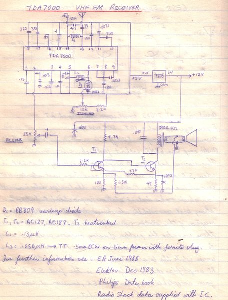
It's very similar to the EA circuit I
used with a varicap diode. So, it seems that the lower Q of the varicap
does not seem to be a problem.
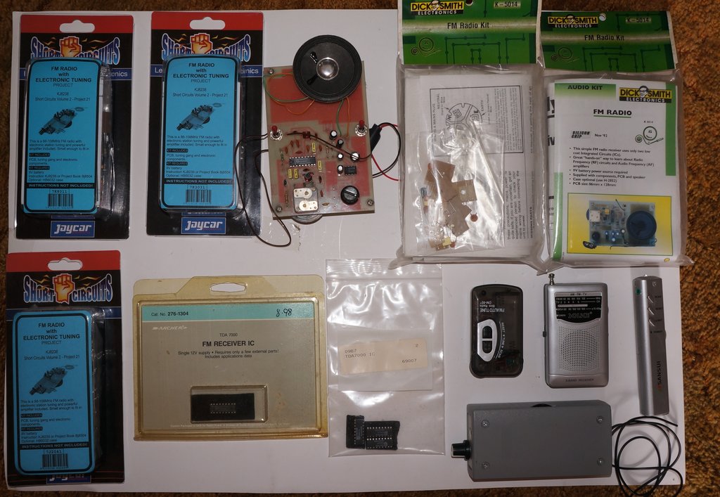
You could say the TDA7000 is my favourite IC. Here's some of my
collection. The three commercially made radios use a TDA7088T clone.
