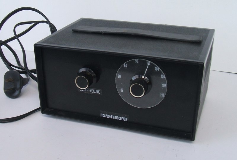
New dial and labelling has transformed the appearance.
New dial and labelling has transformed the appearance.
This project goes back to 1990 when I was
first experimenting with the TDA7000 FM receiver IC.
The TDA7000 was designed by Philips in
the late 1970's, and details
are here. The advantage of the TDA7000 is that it allows VHF FM reception
with only one adjustable tuned circuit. No IF transformers or ceramic filters
are required. As has been described in the TDA7000 article, this is achieved
by using a low IF of 70kHz. Such a low frequency allows audio type op-amp
circuitry to provide the necessary gain and selectivity.
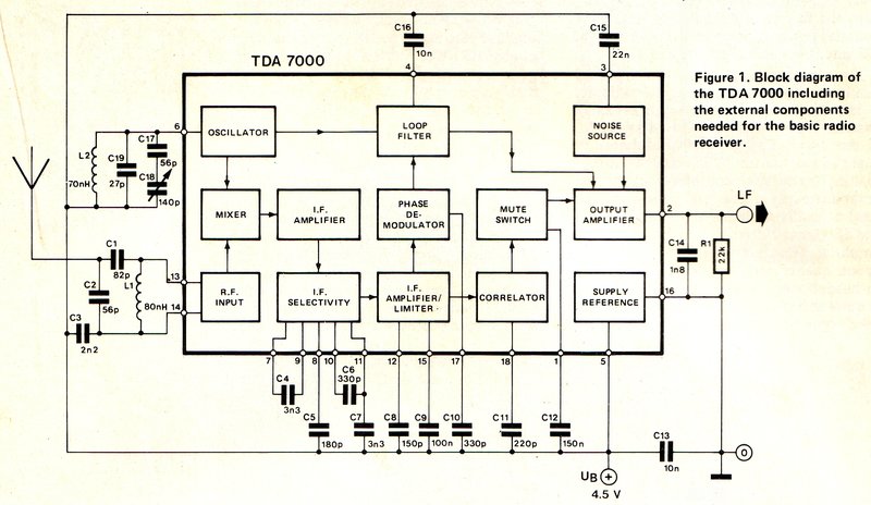
Basic application of the TDA7000.
At the time I did not have PCB making facilities,
so I ordered the PCB intended for an Electronics Australia project - the
June 1988 "2-Chip FM Receiver". As presented by EA, this used the TDA7000
in conjunction with an LM386 audio amplifier, and the whole circuit ran
off 9V.
The use of an LM386 was not to my liking;
this being a noisy class B design. And, the method of tuning was crude,
using a trimmer capacitor. My adaptation was to use varicap tuning and
an external class A amplifier. With a BB809 varicap diode and a 5V regulated
supply, it was easy to modify the tuning circuit to use a 10k pot.
The output of the IC fed a two transistor
amplifier using AC127 and AC187 germanium transistors. The two PCB's were
simply mounted on a piece of wood, and the whole lot ran off 12V.
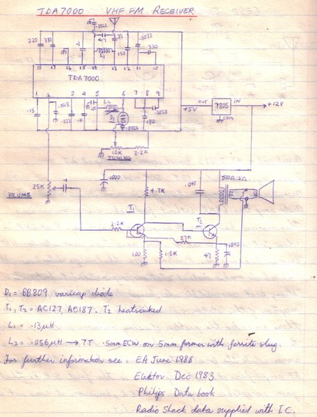
First use of the TDA7000. Audio was amplified by a two transistor
amplifier. There is an error in the circuit in that the de-emphasis capacitor
at pin 2 is actually .0022uF.
Soon after I decided to rebuild it, but
this time in a more practical form. It was to be in a plastic case, and
use valves for the audio amplifier.
For a compact construction which would
fit in one of the available cases, I decided to use a transformer for the
valve heaters only, with the B+ derived from the mains. This was in fact
my first live chassis receiver project. Since one side of the mains is
connected to the chassis, this type of construction requires a lot of care
if it is to be safe. It is absolutely essential that nothing connected
to the chassis can be touched from outside the case. For this reason, all
exposed screws were nylon. The speaker connections have to be made via
a transformer with mains rated insulation. Likewise, the aerial connection
must also be isolated with mains rated capacitors. Finally, potentiometer
shafts and knobs must not present a shock hazard.
1990 version was very plain in appearance and had audio amplifier
problems.
The chassis was a simple flat piece of aluminium to mount the components. This was secured to the bottom half of the case with four 3mm nylon nuts and bolts.
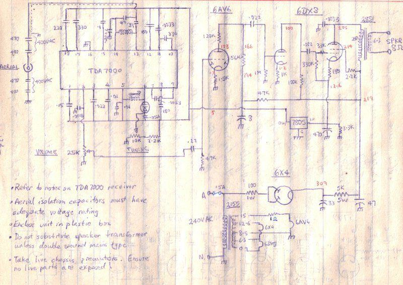
First version of the mains powered circuit (1990).
The amplifier circuit was now based around
a 6AV6 and 6DX8, with a 6X4 rectifier. A DSE-2155 multi-tap 1A transformer
powered the valve heaters. They were arranged to spread the loading over
the whole secondary winding, as simply running the heaters in parallel
from the 6.3V tap would be in excess of the current rating, drawing 2.52A.
As it was, the arrangement used resulted in the transformer being used
just slightly over its full power rating.
While the receiver functioned, it had
two problems. The audio gain was excessive. Additionally, the sound quality
was unpleasant, being shrill and with excess treble. The method of obtaining
5V for the TDA7000 didn't work as well as I'd hoped, and there was a failure
of the 6X4 early on. These latter two problems were addressed, and the
audio gain reduced simply by removing the 6AV6. While there was some improvement,
the sound still wasn't right.
The appearance was very bland with just
two knobs on the front, and two crude Dymo labels designating the Volume
and Tuning controls.
As such, the receiver sat in a cupboard
for many years and was seldom used. With renewed enthusiasm for the TDA7000,
and a much greater electronics expertise, I finally got around to doing
something about it!
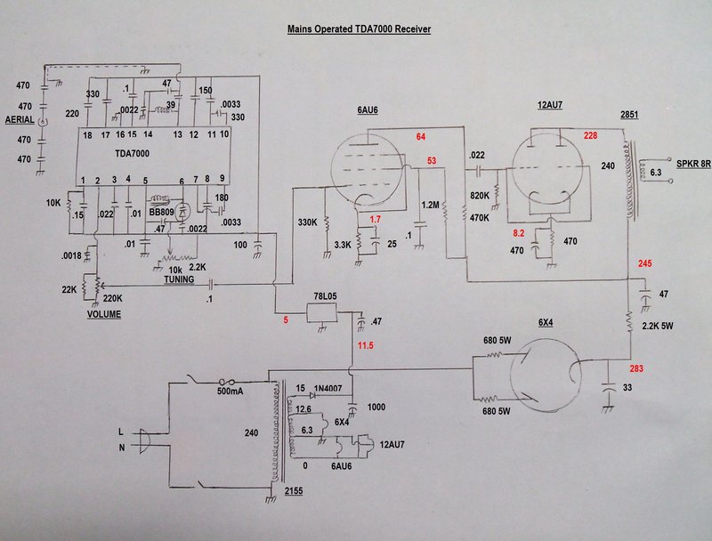
The New Receiver.
New receiver works well. Note the 10k resistor at pin to disable
the muting.
The TDA7000.
This part of the set remains unaltered,
and is the stock standard circuit. However, I took the opportunity to disable
the muting by including a 10k resistor connected to pin 1. As I have become
familiar with the TDA7000 over the years, it does seem the better way to
operate it, and improves weak signal reception.
A 78L05 regulator feeds the TDA7000, as
it is limited to maximum of a 10V supply. Also, the supply must be regulated
because varicap tuning is used. Any supply voltage variations will thus
affect the tuning.
Varicap tuning is based around a Philips
BB809 diode, which is connected across the local oscillator circuit at
pins 5 and 6. As the reverse bias increases, capacitance decreases,
and vice versa. Tuning voltage is derived from a 10k pot, with a series
2.2k limiting the voltage, and thus the minimum capacitance. The receiver
tunes from about 87 to 110Mc/s. The local oscillator is a few turns on
a Neosid former with adjustable ferrite core.
RF input is fed into a fixed tuned circuit at pins 13 and 14. This is really a high pass filter to prevent lower frequency signals, such as AM stations causing interference. Since the receiver is live chassis, the aerial input is isolated with two 470pF 400V AC capacitors in both the active and earthy sides of the aerial socket. These have sufficiently low reactance to pass the VHF signal, but at 50c/s the reactance is so high that the current which can flow is not a shock hazard. The use of two capacitors provides an extra measure of safety should one break down. This is more than many commercial designs use.
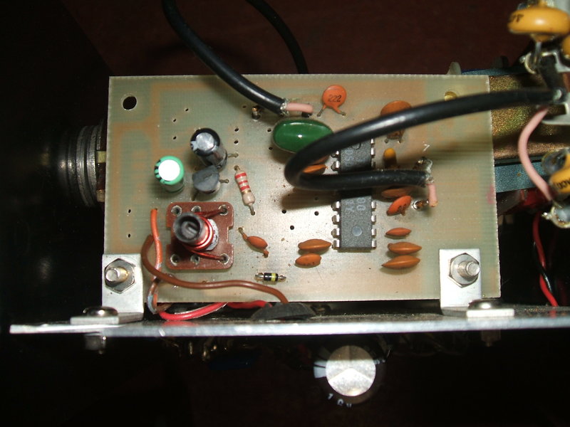
TDA7000 PCB. 78L05 occupies the space where the LM386 would normally
be. Varicap diode visible at bottom of PCB.
The optimum audio load at pin 2 is 18-22k, and in the previous circuit this was a 25k volume control. One of the improvements I wanted to make was to include an on/off switch, and the easiest way to do this was with a switch pot. I was not comfortable using a metal switch for the mains should it become live - and, yes, I have seen it happen. However, 25k switch pots are not plentiful in my parts collection, whereas I did have some 220k ones. By paralleling a 22k across a 220k pot, the TDA7000 sees the correct load.
I also took the opportunity to tidy up the construction by using the unused tracks and pads for the LM386, for the 78L05 circuitry. Previously, a 7805 was mounted on the chassis.
Audio Amplifier.
An easy way to provide mains isolation
for the speaker is to use a mains power transformer, as the output transformer.
With the correct turns ratio, the output valve will work into the correct
load. I used a common 2851 transformer which has a 240V primary, and a
12.6V CT 150mA secondary. If the 6.3V tapping is used, the turns ratio
is 38:1. The impedance ratio is the square of the turns ratio. So, if we
were to connect an 8R speaker to the 6.3V winding, the impedance as seen
from the 240V winding will be 1444 x 8 = 11.5k.
With a 250V B+, this conveniently suits
output valves drawing about 20mA of plate current.
The valve chosen was a 6DX8/ECL84 triode
pentode. The pentode was originally intended for video output use, but
Philips in Australia gave it official audio ratings, and it was a popular
valve for medium power output stages, particularly in TV sets. A 6AV6 triode
initially was used to drive the 6DX8 triode, before the signal proceeded
to the pentode. As it was, the gain was too high. Some reduction in gain
was had by splitting the 6AV6 plate load resistor, and leaving all cathode
resistors unbypassed. Even so, gain was still too high. The 6AV6 was removed
altogether which eliminated this problem.
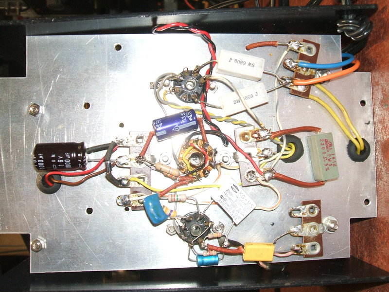
Under chassis view.
Output Transformer.
However, there remained another problem,
which is that of using a mains transformer as a single ended output transformer.
Since the laminations are interleaved with no air gap, the core begins
to saturate and lose inductance, because of the DC flowing through the
primary winding. The same occurs when using most PA line transformers,
since they too are not designed to have DC flowing through any windings.
Proper single ended output transformers have the laminations arranged in
an E-I configuration with an air gap. The result of using a transformer
with interleaved laminations is an unpleasant sound which is quite tiring
to listen to. It's best described as having little bass with a very pronounced
treble response. Unfortunately, trying to correct the frequency response
simply by using a large plate bypass capacitor, or a frequency selective
feedback circuit does not achieve much, it still sounds awful.
Two ways around the problem are to; 1)
keep the plate current low compared to the core size, or 2) use a triode
output valve. Some discussion of the problem is found in this
article.
To overcome the problem with the new receiver,
I decided to use a triode output valve. Many options suggested themselves.
12B4 was one of them, but for class A operation, plate voltage was limited
to 150. The triode connected 6AW8 as used in this Fremodyne
was another good amplifier, but again limited to 150V. Finally, I decided
to base the amplifier on my
2nd Pulse Counting FM Receiver.
This uses a 6SN7 with both triodes in
parallel for the output, and gives excellent sound using a PA line transformer.
It is driven by a 12AX7 and has good sensitivity; enough for the TDA7000.
To keep heater current down, I decided
on the 12AU7 which is electrically equivalent to the 6SN7, but with only
300mA heater current. To drive it, I could have used a 12AX7, but as there
was already a vacant 7 pin valve socket hole in the chassis, where the
6AV6 was, I decided to try a 6AU6 configured for maximum gain. If more
gain was needed, the 12AU7 could be replaced with a 12AT7. The triode output
means that negative feedback is not important.
It all worked very well. Plate current is about 17mA. Output power is 235mW into 8R, and sensitivity is 26mV rms.
Power Supply.
The valve heaters are powered from the
secondary of the power transformer as before. The power rating of the transformer
is 15VA, and by arranging the heaters as shown, the current and power are
within ratings. The 6X4 draws 600mA, as does the 6AU6 in parallel with
the 12AU7. So, in series, the heaters draw 600mA at 12.6V. By returning
the mid point to the 6.3V tapping, the heater voltages are kept equal despite
any slight differences in heater current there might be.
The 15V tap is half wave rectified to
produce 11.5V DC for feeding the 78L05 regulator. However, the input to
the rectifier is actually 8.7V since it's the 6.3V tapping that's earthed
and not the 0V.
In the first version of this receiver,
the 7805 was fed with current from the output valve current. This didn't
work too well with tuning drift problems. This came about because of the
cathode voltage varying with the audio. In retrospect, a larger input filter
for the 7805 would have helped. Since there is already a low voltage source
from the power transformer, it made better sense to use this instead, and
the problem was eliminated.
B+ comes from rectifying the mains with
a 6X4. It will be noted that the original circuit used a 100R surge limiting
resistor. This limits the peak cathode current caused by the first filter
capacitor charging. Unfortunately, 100R was too small, and the 6X4 failed.
The circuit was modified so each plate now sees 680R. An ordinary RC filter
is used with the resultant B+ being 245V.
Since the B+ is not isolated from the
mains, the chassis may be 240V AC above earth depending on the mains polarity
powering the receiver. Of course, I wired it so the chassis is neutral
with a correctly wired mains supply.
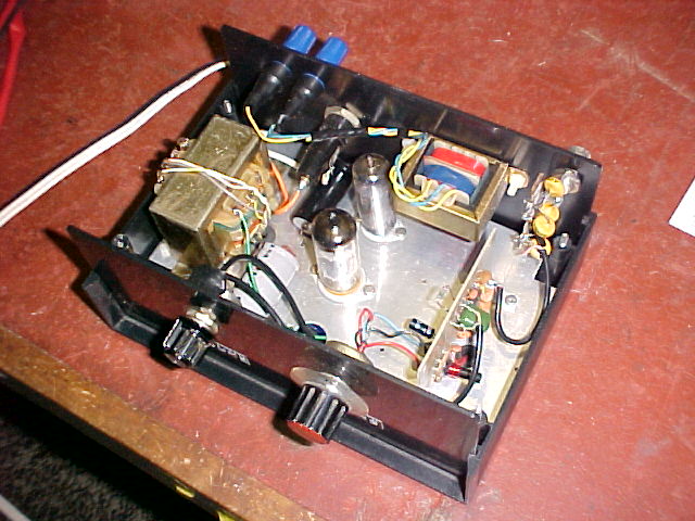
Construction.
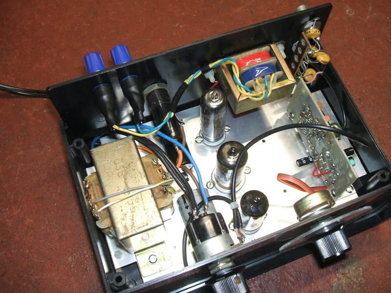
Internal view of the new receiver.
The most important aspect of construction
was to ensure that no live parts can be contacted from outside, and of
course that a fully insulated enclosure was used. The screws securing the
chassis and the output transformer are all nylon types, as was the screw
securing the aerial socket isolating tagstrip. If the output transformer
mounting should become live from something coming adrift inside the case,
it will thus not present a shock hazard if the screws are touched.
The speaker terminals are covered in heat
shrink tubing for the same reason.
It is possible, though very unlikely,
that the potentiometer casings could become live. The potentiometers were
mounted on the plastic front panel for this reason. Since the knobs are
plastic, the risk of shock is minimal since one would have to grip them
so tightly for the skin to make contact with the grub screws. Besides,
the volume control has a plastic shaft anyway.
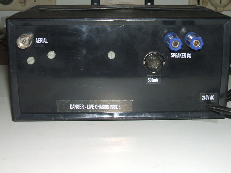
Rear view. Note the nylon screws.
The case was completely re-labelled with white on clear Dymo. The biggest improvement was to make up a proper dial. This was of the type I first used in this receiver. It is simple, but effective and totally transforms the appearance. A perspex disc is turned up in a lathe and screwed to the back of a knob. A line scored into the disc, and filled in with either white or black, depending on background, completes it. Calibrations are then attached to the front panel behind the disc.
Performance.
The transformation has totally changed
the receiver. It is not only nice to look at, but performs very well. 2NUR
comes in quite well with just an indoor aerial, despite being 135km away,
and my location being in the null of its radiation pattern. Clearly, given
the ease of using varicap tuning, and that it does not detract from performance,
there is little point in using a tuning capacitor with the TDA7000.
For the first time, it's a very pleasant
receiver to listen to. Frequency response is good, and so is the bass response.
It sounds particularly good with decent headphones. Despite not having
a vernier dial, it is easy to tune, with the potentiometer providing 270
degrees of rotation compared to the usual 180 degrees of a variable capacitor.
There is some hum evident with headphones, but this would no doubt be eliminated
with a simple decoupling network in the B+ supply to the 6AU6.