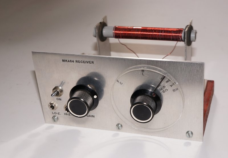
Receiver in its final form.
Receiver in its final form.
This receiver is based on a kit from the
Thai based Future Kit. The catalog number is 709, and the design uses the
well known MK484 or TA7642 AM radio IC, which replaced the ZN414. The kit
also includes a two transistor amplifier. A detailed article on ZN414 receivers,
and a brief description of the kit is given here.
As purchased, the kit is the 'short form' type; that is, only the PCB and
components are provided sufficient to get the circuit working.
Any kind of enclosure, and knobs or dials,
are left up to the constructor.
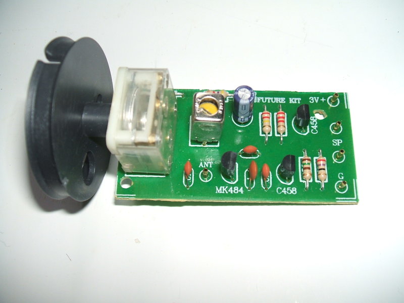
Parts provided with the Future Kit 709. The tuning knob is actually
a dial drum.
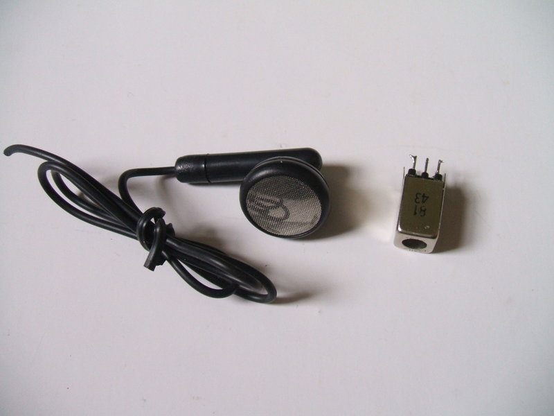
The earphone and oscillator coil were not used.
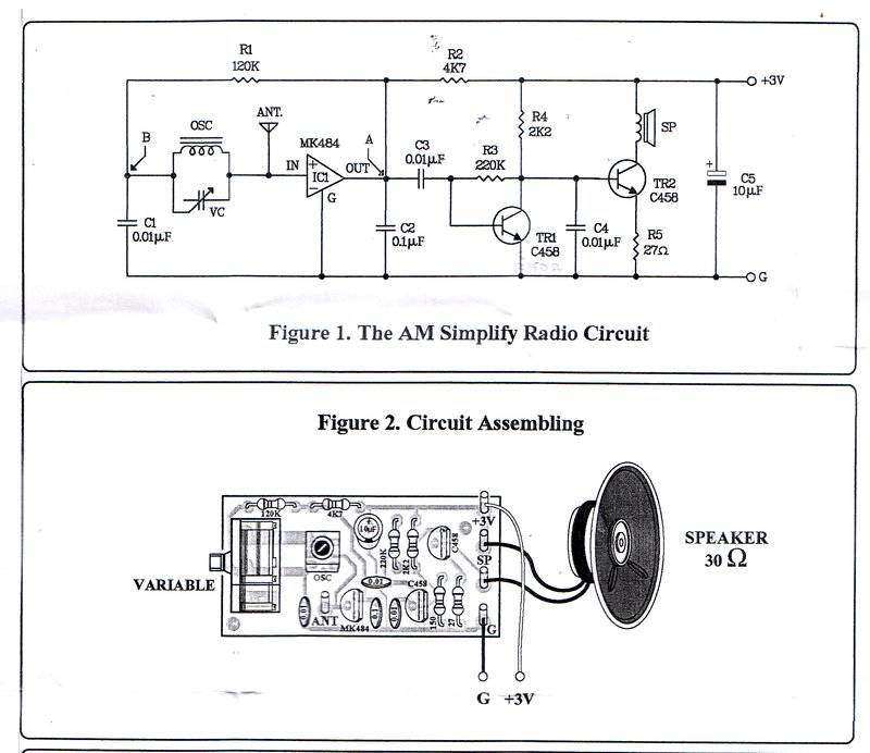
Circuit and PCB layout of the Future Kit. The IC supplied was a
TA7642 instead of a MK484.
The circuit is quite conventional, although
a 3V supply is used rather than 1.5V. To accommodate this, the IC load
resistor has been increased to 4.7K, up from the usual 470R to 1K. Output
feeds a two transistor amplifier, which drives a magnetic earphone. Despite
the wiring diagram showing a loudspeaker, the circuit can barely operate
one. It must be regarded as an earphone only receiver. The supplied earphone
has obviously been cut off a stereo pair. The remaining lead length is
too short to be usable.
The idea of using an oscillator coil for
an aerial coil is novel but practical, if the inductance and tuning capacitance
can cover the required frequency range. With the circuit constructed as
per the kit design, it certainly worked, but tuning range was insufficient.
I found my particular receiver was unstable
on 3V and worked better on 1.5V. This was not particularly surprising.
Why the AGC isolating resistor is 120K instead of the standard 100K is
unknown, but it seemed harmless enough to leave it as is.
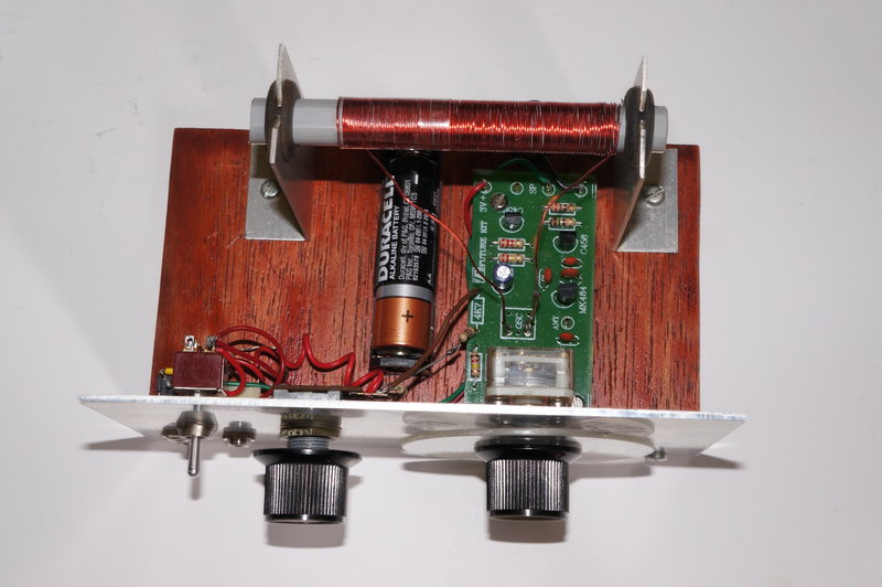
Above view of the completed receiver.
It was decided to use a simple wood base and aluminium front panel type of construction, since I had not intended this to be a fully portable receiver. Some kind of proper tuning dial was required, instead of the plastic drum supplied, which is obviously meant to be used with a strung dial.
Dial.
A vernier dial is not really required
with a receiver like this, since the selectivity isn't quite knife edge.
But, something better than just a plain knob was required. I decided to
make a simple dial with a plastic disc. This was actually made out of a
perspex divider from a Capstan cabinet drawer divider. I turned it into
a circle on my Unimat miniature lathe. By drilling a 6mm hole in the centre
of the perspex, it could be secured to the lathe chuck with a 6mm nut,
bolt, and shake proof washer.
One the disc was cut out, a line was scored
from the centre to the edge to function as a pointer. It was filled with
black ink from a permanent pen.
Next, the disc was attached to the back
of a knob using short 2.5mm countersunk screws. As it happened, the knob
used already had holes in just the right position and it was a simple matter
to tap them for 2.5mm.
The end result looks far better than an
ordinary knob, and a dial scale can be made up with station call signs
or frequencies and placed behind the knob.
Close-up of the adaptor shaft fitted to the tuning capacitor.
It is unfortunate that the modern plastic
dielectric type of tuning capacitor has a short shaft which is designed
specifically for use with a matching dial drum, or thumb wheel knob. To
use it with a normal 1/4" knob requires an adaptor shaft to be made up.
To do this, I use an off cut from a pot
shaft. A 2.5mm hole is drilled through the shaft on the lathe. To prevent
the shaft slipping relative to the tuning capacitor shaft, it's necessary
to do a bit of filing, so that a slot is formed, which engages with the
squared off shaft sides on the tuning capacitor shaft. A suitable length
2.5mm screw then holds the two together.
Because the earphone sockets were to be
mounted on the front panel, and that doing so required that the panel be
live at 1.5V, it was important that the tuning capacitor shaft be insulated.
This was easily achieved with a piece of heatshrink tubing. Since the tuning
capacitor shaft is connected to the input of the IC via the aerial coil,
it's possible to damage it if the shaft touched the front panel.
The tuning capacitor itself is mounted
to the front panel with 2.5mm screws and spacers. It's essential to see
that the screws do not protrude inside the body of the tuning capacitor,
or the plates will be damaged.
Assembly.
A piece of 1/2" thick plywood, 80 x 135mm,
was used for the base. It was stained to improve the appearance. To the
front edge of this was secured the front panel. This is a piece of aluminium
70 x 135mm.
The Future Kit does not provide for adjusting
the operating conditions of the IC, which, from experience is essential,
if full performance is to be obtained. Initially, I had ideas of using
the Technicraft method of gain control and so installed a 10K pot on the
front panel. See the ZN414
article for details on this.
Along with the pot was a power switch,
and two 3.5mm sockets.
One of the sockets was to operate low
impedance magnetic earphones, and the other was to allow the use of high
impedance magnetic or crystal earphones.
A single AA cell holder was mounted to
power the receiver. The Future Kit idea of using 3V was not in line with
the MK484 data, and even though the load resistor (Ragc) was higher than
the usual 500R to 1K, I'm not sure it's the right way to operate this IC.
Aerial.
As previously mentioned in the ZN414
article, the Future Kit comes with an oscillator coil which is intended
to function as an aerial coil. This requires a wire aerial which is not
as convenient as a ferrite loopstick. Furthermore, the inductance of the
supplied oscillator coil is not sufficient to cover the full broadcast
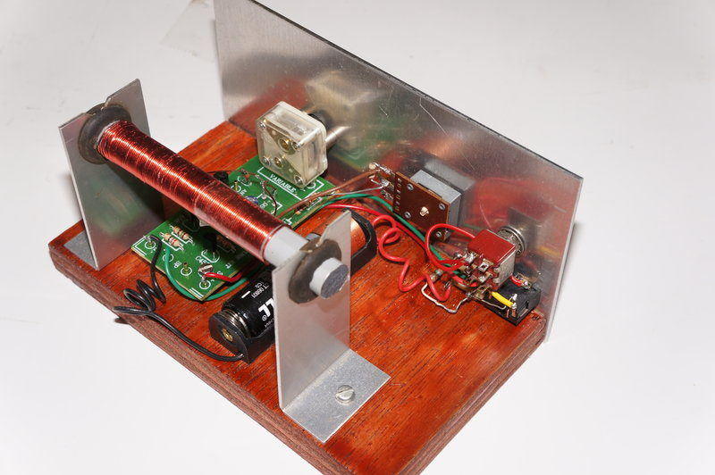
band. My version of the receiver was to therefore use a ferrite loopstick.
This was mounted on two aluminium brackets fitted with 3/8" grommets. The
rod is a push fit into the grommets. It is important to note that the brackets
have notches cut into them where the grommets sit. If this was not done,
the ferrite rod would see the holes as shorted turns, ruining performance.
The coil was wound using some likely looking
copper wire, with enough turns to cover the broadcast band, using the supplied
180pF tuning capacitor.
Poor Selectivity.
Unfortunately, when first powering up
things were not as they should be. It was impossible to eliminate 2FC and
2BL being heard right across the band unless the aerial was rotated to
exactly 90 degrees away from the transmitter direction. To explain for
those outside of Australia, these are the two Sydney ABC transmitters with
a power of 50kW. Their transmitter site is 46km away. The other Sydney
stations are typically 5kW and are 58km away.
This was very much at odds with the "Funway"
ZN414 receiver and the Hobby Electronics YS414 receiver. These two receivers
perform excellently, and in my home location are virtually as good as a
superhet. If anything, the improved gain control should have improved selectivity.
So, what was wrong? I reverted back to
the 'normal' method of gain which entails Ragc being adjustable. This didn't
improve selectivity, but it did improve the sound quality. Strangely, the
Technicraft method of gain control resulted in distortion and the output
seemed unusually noisy. This was not as I recall from using it with other
ZN414 receivers.
Perhaps my home made aerial coil had poor
Q using ordinary solid copper wire. I tried a commercially made Litz wire
ferrite loopstick but it did not improve selectivity. I checked there was
not the uncommon mistake of the AGC isolating resistor being shunted across
the input of the TA7642 which would lower the Q. The circuit was confirmed
to be correct.
At this point, not much was left except
for the IC. I checked the performance on my Hobby Electronics YS414 receiver,
just to confirm I wasn't imagining things. I then removed the YS414 from
its PCB and put it in the Future Kit. What a difference!
Performance was excellent. No more ABC
across the dial, and various rural stations could be tuned in. 2LT, 40km
distant on 900kHz, uses a directional transmitter which is aimed away from
my area. Reception was excellent and better than a lot of superhets. Not
only that, there was no interference from 2GB in Sydney on 873kHz.
TA7642 is not ZN414.
Suitably suspicious, I tried another TA7642
and the selectivity was just as bad as with the first one. It was now obvious
that the TA7642 is not exactly the same as the ZN414/MK484/YS414. The data
from the TA7642 shows the input resistance being 3M instead of the ZN414's
4M, but selectivity shouldn't be reduced to the extent it was by that.
I tried tapping down the input on the aerial coil to accommodate a lower
input resistance, but all it really did was to reduce volume.
What to do? As it was, the receiver was
just not practical and would be annoying to use. Rather than use one of
my real ZN414's which are now collector's items, I installed an MK484 and
was pleased to have the performance this receiver should provide.
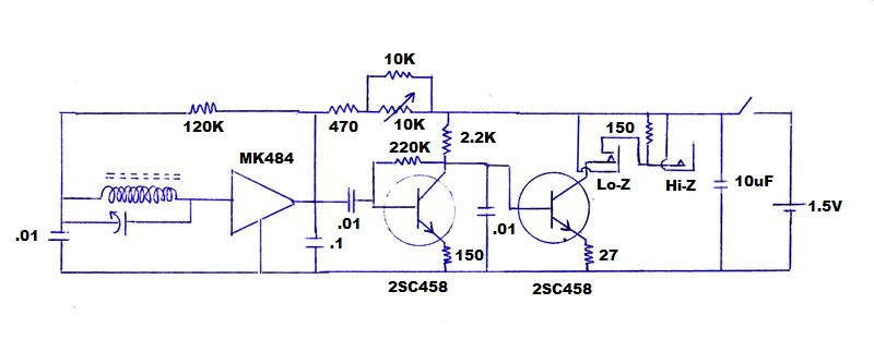
Final circuit with modifications. Use a 5K pot instead of the 10K
type and associated 10K fixed resistor if duplicating this circuit.
Given the now excellent performance, there
was no point in reverting back to the Technicraft method of gain control,
and I left the circuit using the conventional method. Ideally the pot should
be 5K for this, but as I'd cut the panel especially for the 10K type initially
used, I simply connected a 10K resistor across it to prevent the otherwise
large dead spot in its operation.
As the circuit is designed, the amplifier
suits earphones around 30R. I also wanted the option of a crystal earphone.
This of course presents an open circuit in the DC sense, and to use it
with this output stage requires a suitable load resistor. This turned out
to be 150R for optimum performance. By suitably connecting the two sockets
and the switch contacts therein, the 150R load resistor would only be in
circuit when the crystal earphone was plugged in. Not shown on the circuit
is that the low impedance earphone socket is actually a stereo type with
both channels in parallel.
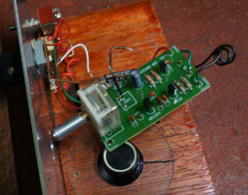
Rear view of the receiver.
Final part of the construction was to label the front panel. Although for something more pretentious I would have printed out a dial scale, I took the easy way out and used transparent Dymo labelling.