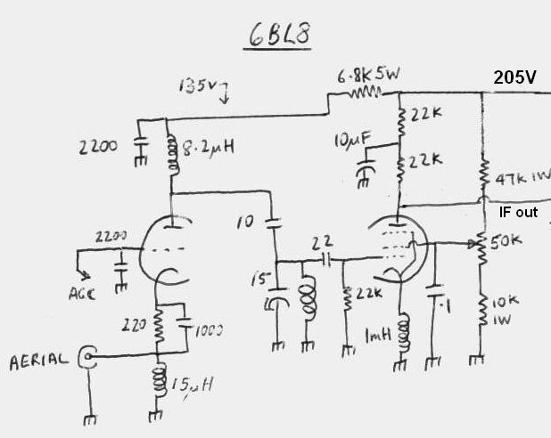
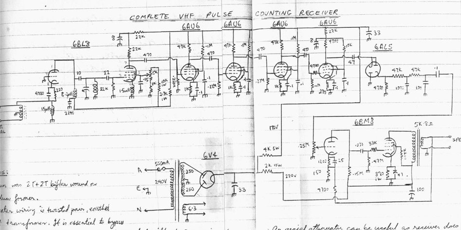
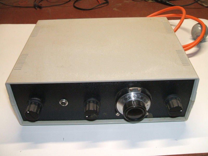
From one of my receivers. Grounded grid RF amplifier feeds an autodyne converter to produce the 200Kc/s IF.
Most constructors have never have
heard of this type of receiver, unless you're into top end FM tuners, or
you have read British electronics magazines from the mid 50's to the 1970's.
I first saw the design in a mid 1960's
Practical Wireless magazine and due to the simplicity I thought it wouldn't
work. How wrong I was! This was in 1990 when I was getting frustrated with
the limitations of super regenerative receivers, prior to the development
of my 12AT7 circuit,
and was looking for other approaches to the 'simple FM receiver' problem.
Concept of Operation.
The pulse counting FM receiver is a superhet
receiver, but differs from conventional FM receivers in two ways. First,
the VHF signal is converted to an IF of 200Kc/s instead of 10.7Mc/s. This
is because instead of a ratio detector or quadrature detector, a pulse
counting detector is used. Its operation requires a low IF. Because of
the low IF, no tuned circuits are required, except one for the local oscillator/RF
input. This dispenses with the necessity to perform any alignment. Beyond
the converter, all stages are resistance capacitance coupled.
Commercially made Pulse Counting receivers
are a bit more elaborate than this. They're often dual conversion, with
a conventional 10.7Mc/s IF which is then converted down to the ~150Kc/s
IF with a crystal locked converter. This is done to prevent image response.
These days, they often use a digital type pulse counting detector which
provides good noise immunity. By passing the squared waveform through a
Schmitt trigger, most of the noise will be removed.
However, for the homemade type of receiver,
we don't need to go to such lengths to get a good quality receiver.
The earliest mention of pulse counting
techniques appears to be in the early 1940's where such a receiver was
used to monitor one of the first FM transmitters on the Empire State building.
It used 807's for the RC coupled IF stage (a bit of overkill) and a 6H6
detector.
The next mention appears in Wireless World
in the late 1940's when Thomas Roddam asks, "Why align FM discriminators?"
and puts forward a pulse counting detector design. Then in 1956, M.G. Scroggie
answers the question with a complete and practical Pulse Counting receiver.
It was this design that provided the basis for subsequent valve receiver
circuits until solid state versions appeared.
Once I had familairised myself with the
operation of this method of FM reception, I settled on a basic design which
has been used in all my receivers with minor variations.
I have built five such receivers up to
the present time and all worked first time, with nothing to align. Other
constructors who have read this article have also duplicated the design
with excellent results. The design is not 'weird' or a 'fluke'. Sensitivity
is
close to, and better than some commercially made superhets. Yes, there
is an extra control to be adjusted which is a tradeoff, but for the person
who wants high quality mono FM, using valves, with simplicity, there isn't
a better receiver. However, the "extra control" can be a set and forget
affair unless you're wanting to get every last microvolt of sensitivity
for low power or distant stations.
RF Amp & Frequency Converter.
I have found best performance, coincident
with ease of construction, results from using a 6BL8/ECF80 at the front
end. The triode is used as a grounded grid RF amp, feeding the pentode
functioning as an autodyne converter. Having such a low IF means that the
signal can be tuned in with the local oscillator either side of the carrier.
This can be advantageous if there's an interfering station on a nearby
frequency. Image response is a non issue as FM stations do not transmit
on adjacent frequencies in any given area.
The original Wireless World article used
a 12AT7/ECC81 local oscillator driving a passive germanium diode for frequency
conversion, but the gain is obviously lower than an active first detector.
From one of my receivers. Grounded grid RF amplifier feeds an autodyne
converter to produce the 200Kc/s IF.
RF Amplifier.
The VHF signal is fed into the triode
of a 6BL8/ECF80. This operates as a grounded grid RF amplifier stage and
thus suits a low impedance input. RF chokes are used for plate and cathode
loads. As such, this stage is untuned and provides not much gain. However,
its purpose is to isolate the aerial from the following stage; which is
the autodyne frequency converter.
The aerial needs to be isolated, otherwise
aerial loading effects will cause the oscillation level to vary excessively,
to the point of causing the oscillator to stop in some instances.
It also reduces local oscillator radiation
from the aerial.
A characteristic of the 6BL8 is that there
is an internal shield between the triode and pentode. It is connected to
the pentode cathode. With the original intended use of this valve as a
mixer in a TV tuner, the pentode cathode is earthed, and therefore so is
the shield. However, in this circuit, the cathode is floating at RF and
the shield becomes ineffective. This means there is stray capacitance between
the triode plate and the pentode cathode. It appears this is the cause
of an interesting effect, which is that at the 108Mc/s end of the band
sensitivity actually drops off with the RF amplifier operating at full
gain. Yet, at the 88Mc/s end of the band, full gain of the triode is required.
It is the intention that the VHF signal
is coupled from the triode plate to the pentode grid via the 10pF and 22pF
condensers. But, when signal is fed to the pentode cathode as well (via
stray capacitance), it's out of phase with that fed into the grid and so
the effective input signal is reduced. Obviously, the stray capacitance
has more effect at the higher frequency end of the band.
The result of this is that, ironically, the RF amplifier triode needs to run at reduced gain or be cut off entirely, if full sensitivity is to be had at the 108Mc/s end. The stray capacitance between the triode cathode and the the pentode is sufficient to couple the signal through into the mixer. In fact, for those that want to simplify the design, the aerial can be connected into the tuned circuit by a 1.5pF condenser and this will give the same sensitivity at the 108Mc/s end. However, gain drops towards the 88Mc/s end. One could use the triode for some other function in a simplified receiver.
The upshot of all this is that if full
sensitivity is required at the 108Mc/s end, an attenuator of a few dB has
to be connected at the aerial input, and removed for reception at the 88Mc/s
end. The proper way to do this is of course, to include AGC, so that the
RF amplifier gain is reduced or increased as required.
It is quite possible that if separate
isolated valves were used for the RF amplifier an converter, this peculiar
effect would not occur.
The cathode and plate chokes are not particularly critical. If a balun is used at the input for 300 ohm balanced input, the cathode choke is not required as the balun provides DC return. See the first version circuit. Preliminary tests seem to indicate the plate choke can be replaced with a 10K resistor, but detailed measurements have not been taken with regards to this.
Frequency Converter.
The frequency converter is of the autodyne
type; that is, the mixer is self oscillating. Only one pentode (or triode)
is required. Here, the pentode operates as an electron coupled oscillator
by virtue of the cathode choke and the stray capacities in the valve. The
tuned circuit feeds the grid. It determines the frequency of oscillation.
Conveniently, because the IF is only 200Kc/s, the received frequency is
so close to the oscillator frequency, that we can use the same tuned circuit
for both tuning the RF input as well as the oscillator. While the tuned
circuit is not right on the received frequency, the selectivity of this
circuit is such that a signal 200Kc/s away is not attenuated.
The operating point of the converter is
important. Best conversion efficiency (and thus sensitivity) occurs when
the oscillator is operating at a low level; just above the point where
oscillation starts. Because the oscillator level varies across the band,
it is necessary to adjust for the optimum operating point, and so a control
(the 50K pot) is provided to vary the screen voltage of the pentode. For
strong signals, the operating point is not so critical and the control
only needs to be set once.
Because of the low IF, very strong signals
can actually cause oscillator pulling. That is, the local oscillator actually
locks to the signal, and as a result there is no difference between the
local oscillator and signal frequency. Thus, no IF is produced. To
prevent this, I have included AGC to reduce signal strength to below that
which causes oscillator pulling. The negative voltage present at the limiter
grid is used to reduce the gain of the RF amplifier.
Due to the low IF, the plate load of the
pentode is a 22K resistor, rather than a tuned circuit. This feeds the
IF amplifier which subsequently provides the necessary selectivity.
IF Amplifier.
The original Wireless World article used
a two stage IF amplifier using 6BX6/EF80 valves with the response as shown:
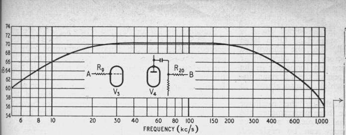
Gain is about 4000, and input voltage (to
the IF) should be at least 1mV for optimum performance of the following
limiter and detector. However, the converter gain is high, so the receiver
works well at signal levels much less than this.
So how do we get this response with no
coils? It's quite easy actually when you consider valve input and stray
capacitances. Each of the 6BX6's has a 4.7K resistor in series with
the grid. In conjunction with the grid capacitance there is a degree of
low pass filtering. The high value of plate resistors (18K), adds to this
and so we have the top frequency response set to around 250Kc/s.
The low frequency response is set by the
270pF grid coupling condensers in conjunction with the 100K grid resistors.
It starts to fall off at about 20Kc/s.
In the receivers I have constructed, I
have departed from the Wireless World IF amplifier design in some instances,
but the results are the same.
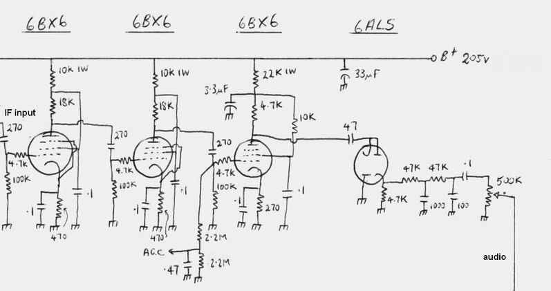
Complete IF amplifier, limiter, and detector. The .47uF can be reduced
to .22uF or .1uF for faster acting AGC.
Limiter and Detector.
Limiting is done in the conventional way
with a third 6BX6 operating with low bias and a low value plate load. Because
of the low frequency used, it is quite easy to observe the waveform with
a CRO throughout the IF, limiting and detection stages. Because the limiter
is operated with a low bias, the signal fed into the grid causes grid current
to flow, and thus produces a negative voltage which is consistent with
signal strength. This negative voltage suitably filtered can be used for
AGC and to drive a magic eye tuning indicator.
The clipped waveform from the limiter
plate is differentiated, and applied to a pulse counting, or tachometer,
circuit. The higher the frequency, the closer the pulses are together,
and the the higher the resulting DC from the detector, and vice versa as
the frequency decreases. So, we have a frequency to voltage converter which
is what we want for FM demodulation. The greatest advantage is there are
no tuned circuits to get out of alignment, causing distortion.
Despite its appearance as a voltage doubling
AM detector, the circuit around the 6AL5/EB91 is anything but. The low
value input condenser (47pf) and the low value load (4.7K) ensure the signal
from the limiter is differentiated. Filtering is done with a simple RC
circuit which also provides de-emphasis.
Audio output is low at about 100mV, and
the recommended load is 500K. While an ordinary triode pentode audio amp
can be just fully driven, an extra stage of gain is worthwhile.
First Version.
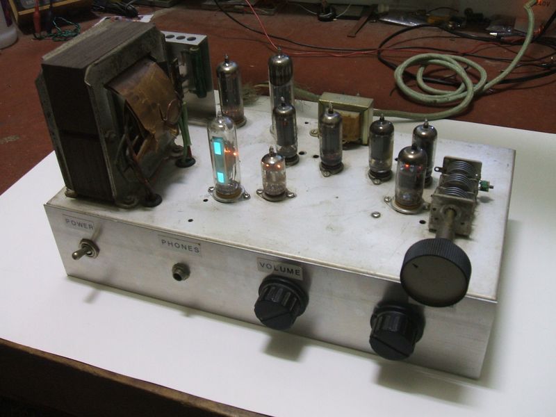
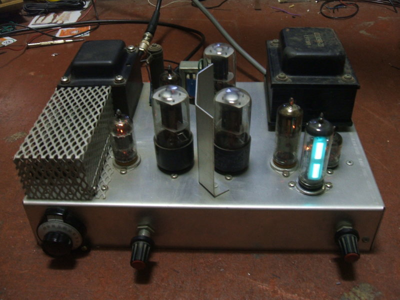
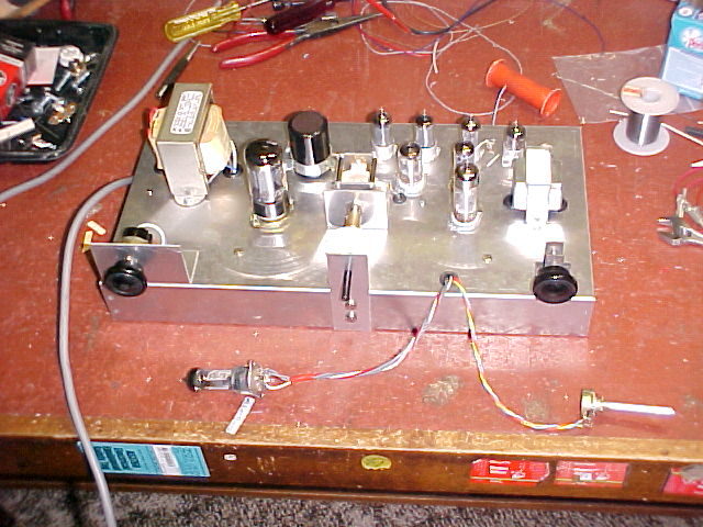
First Pulse Counting FM Receiver, Winter 1990. This is my Super
DX model with 3 stages of IF amplification. Valves are, from back
to front, 6V4, 6BM8,6AU6 x 4, 6BL8 and 6AL5. The magic eye is an EM84.
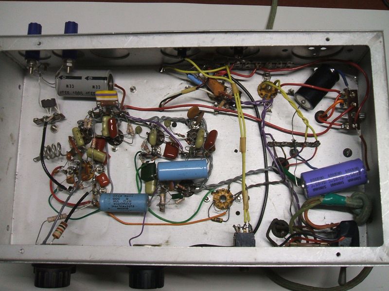
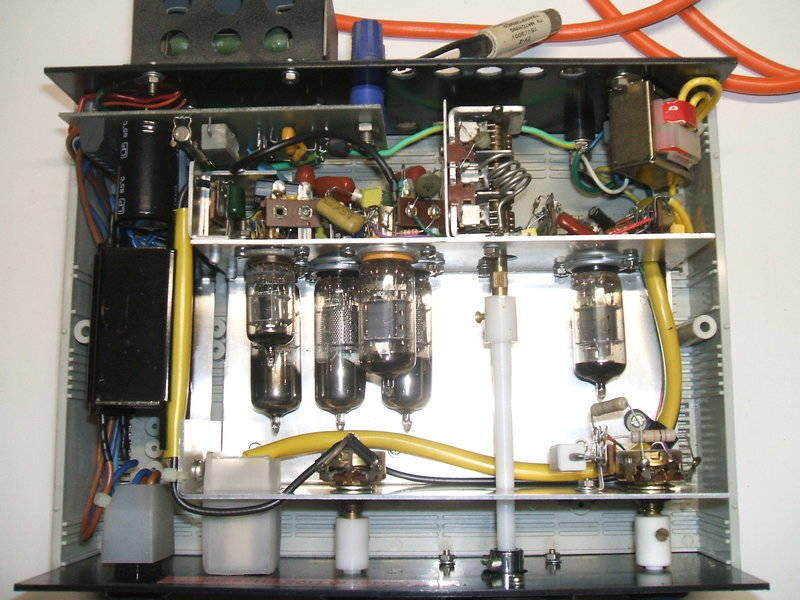
Under the chassis of my first pulse counting receiver.
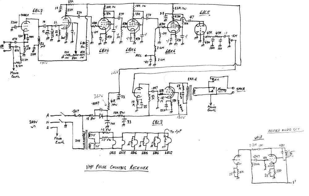
Circuit of original receiver. The 15uH choke in the RF amplifier
cathode circuit is not actually required as the balun provides DC continuity.
I had the basic receiver assembled in one
evening, and due to my scepticism, I'd added an extra IF stage in case
the gain turned out to be inadequate. I was in a state of amazement when
I first powered it up, and was getting Hi-Fi sound with excellent sensitivity.
The following night I'd added a grounded grid RF stage to eliminate the
problems of aerial coupling and absorption effects. With an indoor TV aerial
I had no problems in bringing in all local stations, and the low power
community broadcasters that caused so much difficulty on the super-regen
sets. And there was no SCA/stereo subcarrier beat, no hiss, and no distortion!!
Subsequent experiments proved that stereo
reception was not practical. It appeared that the demodulated signal is
not of sufficient bandwidth, and to increase it would mean reducing the
output. However, with high frequency boost prior to the LM1310 stereo decoder,
it was possible to get results of some sort but separation was just too
poor.
Sensitivity
I did some simple tests with my first
receiver, with the three IF stages, and a Hewlett Packard 8654B signal
generator. Even with no aerial connected there was some difficulty in finding
a clear frequency in the middle of the band as stations just roll in from
everywhere. My initial tests were done at about 90Mc/s, with a 1000c/s
tone. Deviation was set to 70Kc/s. 1uV was discernible, but only just.
Had it been voice or music you wouldn't be able to understand it. 3uV was
better; just readable. At 10uV, the signals are very readable. Noise free
reception commences at about 30uV. Not bad for an FM receiver
with only
one tuned circuit!
For the limiter to start clipping, signal strength
required is much greater; around 500uV. However, this is not important
as VHF is not prone to interference.
I also examined the performance if the
oscillation level control, which sets the frequency converter's operating
point was simply used as a preset control. Much to my surprise, the change
in sensitivity was not as great as first thought as I tuned across the
band, maybe a loss of 10uV or so. Interestingly, this seemed to be around
the centre of the band.
AGC and Magic Eye
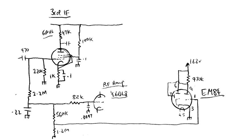
AGC was added to this receiver in October
2018 in order to optimise sensitivity for distance reception (see the description
above). In this receiver, the grid of the 3rd IF amplifier is used as a
source of negative voltage. With the other receivers having a two stage
IF amplifier, the grid of the limiter is used instead. Attempts to use
the limiter grid in this receiver were difficult because the higher gain
of the IF strip meant that the noise level was high enough to create a
permanent negative voltage even when the receiver was not tuned to anything.
Experiments with various delay circuits
were carried out but the result was not as it should be. Further thought
indicated that a negative voltage dependent on signal level should be available
at the third IF amplifier grid. While it is true the IF amplifiers are
mostly operating in class A, if the input signal is greater than the grid
bias, then grid rectification will occur. Indeed it does, and the voltage
is just right for the purpose. A voltage divider feeds the grid of the
EM84 (6FG6) magice eye so that the eye is just about closed with a 1mV
input signal.
6U8 Converter.
It appears that the 6U8 gives slightly
better performance than the 6BL8 for the converter in this receiver. Type
6CQ8 was also tried. This valve is often described as an equivalent to
the 6U8, despite being a tetrode instead of a pentode. Performance was
the worst of the three.
However, it must be pointed out, this
test was to find the most sensitive converter for the operating conditions
in this receiver. 6U8 provides the least critical screen grid/tuning control
adjustment on weak signals.
It should also be pointed out that individual
6BL8's may vary sufficiently to be better than the one originally fitted.
In my area, the desired station is on
103.7Mc/s. It is a weak station from 145km away. Two strong stations, about
60km away, are on 104.1Mc/s and 103.2Mc/s. With the 6BL8 adjustment for
the screen and tuning controls to get the most sensitivity, and least breakthrough
from the adjacent stations, is rather critical. With the 6U8, there is
a noticeable improvement.
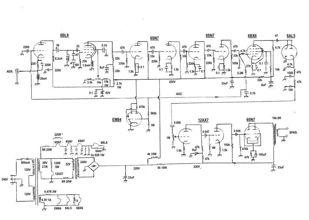
Second Pulse Counting Receiver, October 1992.
This receiver uses 6SN7's for IF amplification, and also uses a 6SN7 fed by a 12AX7 for the audio amplifier. The resulting 'triode sound' is the nicest sounding of all my FM receivers. A series heater circuit is used with modern low voltage transformers for the power supply. This receiver was operated daily for several years at my place of work and never failed.
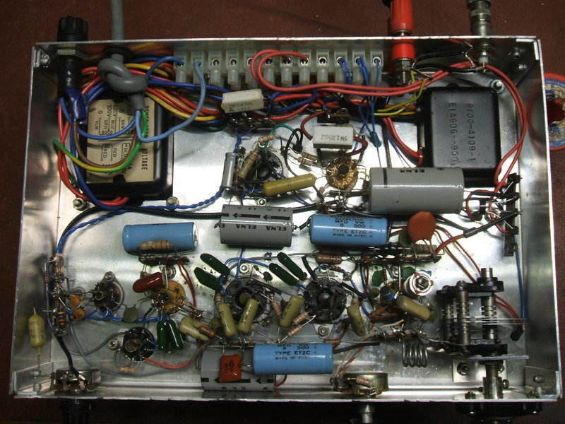
Under the chassis of the 2nd receiver.
A later modification was the addition of
AGC, and more recently a magic eye tuning indicator.
Unmarked heater bypass condensers are 0.15uF.
The circuit differs from the other designs
in that it uses triodes for the IF amplifiers. The operation of the frequency
converter is stabilised by a 62V zener diode. Prior to including this,
the receiver would be susceptable to oscillator drop out - particularly
on weak stations where the converter is only just oscillating. The main
power transformer was obtained from a solid state 1970's stereo amplifier.
The 6.3V winding supplies a little more than 6.3V, hence the 0.47R resistor.
The 29V winding supplies the 6SN7's and 6BL8 in a series heater circuit.
The 12AX7 is supplied separately through its own dropper resistor. Note
that 6BL8 is not a series heater type, and nor are standard 6SN7's. Unless
6SN7GTB's are used, there is the chance of unequal heater voltages. In
my set, the audio 6SN7 needed a 220R 1W shunted across its heater. The
two 82R 1W resistors shunt the extra 150mA from the 6BL8 with its 450mA
heater.
High tension comes from another transformer
used in reverse which feeds a bridge rectifier. This came from a piece
of computer equipment. The output transformer is a Jaycar MM1900 with the
1W tapping used.
The 30pF variable condenser between the
RF amplifier and tuning coil is a Philips beehive type. It adjusts the
signal coupling but can be replaced with a 10pF fixed condenser as per
the other receivers. The heater bypass condensers shown are mounted right
at the valve sockets.
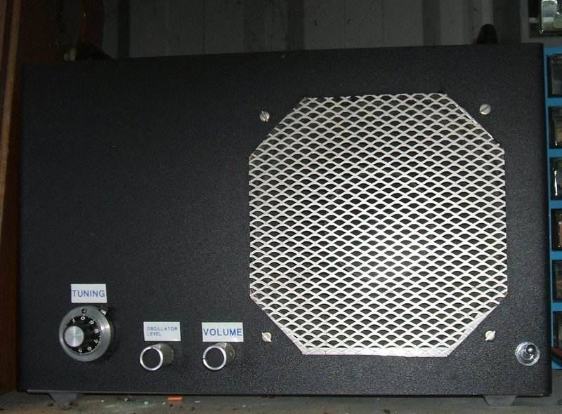
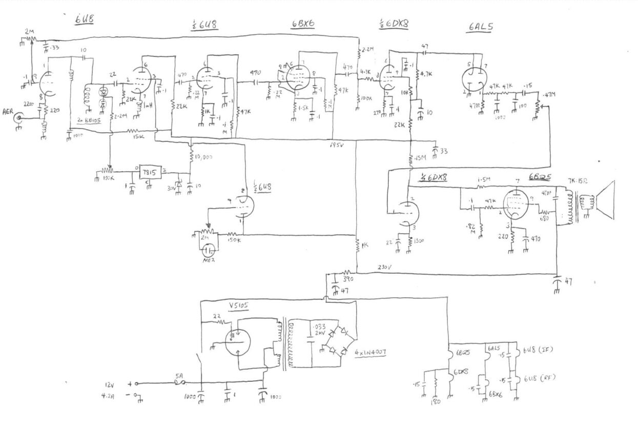
The third pulse counting receiver I built is for 12V operation. It uses a vibrator power supply. Tuning is by a ten turn pot and varicap diodes. Its valves are 2x 6U8, 6BX6, 6DX8, 6AL5 and 6BQ5. It provides the highest audio output of all my pulse counting receivers. While it has good sensitivity and sound quality, the varicap diodes cause drift, as the set warms up over about 20 minutes. An AFC circuit will have to be provided, or a return to variable condenser tuning, to eliminate this.
4th Pulse Counting Receiver
This set was constructed in the Winter of 2000. It was constructed in a plastic instrument case to make a compact and portable receiver. Initially, I used a 6DX8 for the audio, but the heat generated inside the case was too much and so I changed to a 6BL8 with its lower heater and plate current. Extra ventilation holes also had to be drilled.
Note the revised audio amplifier. It is not recommended that constructors
use the power supply circuit shown. No responsibility taken for fatal electric
shock due to incorrect construction techniques.
The power supply is unusual as far as Australian design goes, using a live chassis with a transformer for the heaters only. This was done for space reasons. There was no way any valve type power transformer capable of powering this circuit could fit in the box with everything else. For the B+, the 240V mains is rectified by a 1N4007 and smoothed with RC filtering. No hum is evident even with sensitive headphones.
Very compact inside with 6 valves! On the left are the front end
valves. The bottom row is the 6BX6's, and the 6BL8 converter and 6AL5 are
on the top. Over at the right is the 6BL8 audio valve. This receiver
has a live chassis and has suitable precautions to prevent the user coming
into contact with the mains.
One thing that happened was the dropping out of the oscillator at the high end of the band. I eventually discovered it was due to the original 1.5mH cathode choke. For some reason the one I'd used wouldn't allow proper oscillation. Changing to a different type (axial 1mH) fixed that completely.
Improvements:
Ideas which I haven't actually implemented
but are worth experimenting with. Note that these in no way imply
this is an unstable receiver that suffers from drift. They are merely good
practice to include in any VHF receiver.
1)AFC: The DC present at the detector
output or perhaps the DC on the AGC line could be used to provide AFC as
these voltages peak up on correct tuning. Varicap diodes or using the miller
effect of a triode could be used to control the oscillator frequency. I
did experiment with a varicap diode fed from the detector output
with my first receiver and the idea seemed to hold promise.
2)Regulating the B+: When the mains
voltage changes and the receiver is adjusted to just past oscillating for
the most sensitive point, it may drop out when the mains voltage decreases.
Regulating the B+ to the converter stage at least would overcome this.
Also, the frequency at which the 6BL8 pentode oscillates is affected by
plate and screen voltages (the screen control can actually be used for
fine tuning within limits). Regulation would therefore improve frequency
stability.
3)Regulating the 6BL8 heater: I
have noticed that after a large drop in mains voltage that within a few
seconds the receiver may drift off frequency. The time delay suggests the
heater temperature of the 6BL8 pentode has an effect on oscillation frequency.
So, it would be worthwhile to provide a regulated supply for this as well.
Easiest way is with a three terminal regulator set to 6.3V. As the regulator
has to be fed with DC, consideration has to be given to the
other heaters. Two options are: a) separate heater windings (or separate
heater transformers), one feeding the other valves with 6.3VAC and the
other feeding the bridge rectifier and regulator (it will need to be about
9V to allow for regulator headroom and rectifier losses), b) one winding
feeding a rectifier and regulator to provide DC for all the heaters. The
reason for separate heaters is of course with bridge rectification one
cannot earth both the input and output of the rectifier, and it is essential
that one side of the heater line is earthed.
4)Automatic level control for the oscillation
amplitude of the frequency converter. This would eliminate the "extra
control". Other kinds of frequency converter could also be investigated;
e.g.. pentagrid valves, or separate oscillator and modulator valves.
Thoughts on Stereo:
An attempt was made to connect an LM1310
type stereo decoder to the original receiver. If you wish to experiment,
connect the decoder input to the junction of the two 47K resistors in the
detector output filter. Change the 1000pF to 100pF. Although results of
a sort were obtained, separation was poor, and stereo reception was unreliable.
Later research revealed the problem is lack of bandwidth with the pulse
counting detector as presented. Don't forget the design was optimised in
an era when multiplex transmissions had not been thought of. Don't forget
that the stereo signals are centred about 38Kc/s, hence the need for greater
detected bandwidth. Detected output voltage, and bandwidth of the detector
is dependent on the value of coupling condenser from the limiter to the
detector diodes. The larger the condenser, the wider the pulse, the
higher the output, and the the narrower the bandwidth. So, if you have
ideas about trying the design for stereo reception, a good start would
be to reduce the 47pF, as well as the filtering on the detector output.
However, the detected output will now be of lower amplitude. It would appear
therefore, to compensate for this, the B+ for the limiting stage will need
to be increased. This may mean the 6BX6 will be outside its ratings, and
if so will be necessary to change the limiter valve to something higher
powered. Having said all that, the Zenith stereo multiplex system used
for FM stereo is a limited performer to start with, and requires a signal
far better than that required for good mono reception.
Version 5 Pulse Counting Receiver.
This receiver was the first where I'd included
a magic eye tuning indicator. It is based on my original version, but with
one less IF stage. To enable the 6BM8 to be driven with gain to spare,
an extra audio stage has been added. It is simply a 6AU6 wired as a triode,
and the cathode resistor is unbypassed, as only a low gain is needed.
I have also taken the opportunity to try
my homemade VHF
chokes as the originals are almost impossible to obtain. Constructors
of my VHF receivers have difficulties in getting the original commercially
made chokes I used, and often the substitutes perform poorly or stop the
receiver working altogether. So, now this problem has been solved. I now
recommend the homemade chokes for all the valve pulse counting designs
in all three positions. The same goes for the super regenerative sets.
Because the power transformer only had a 2A 6.3V winding, it was necessary
to include another filament transformer for the 6BM8/ECL82 and 6FG6/EM84
The magic eye is very useful for tuning,
and as a relative signal strength indicator. It also makes it very clear
when the 5K oscillation level pot is adjusted optimally.
Note that the screen grid voltage for
the frequency converter is fed from the same B+ point as the RF amp which
is AGC controlled. The common 2.7K resistor means that the screen voltage
fluctuates with signal strength, and this reduces the necessity to adjust
the 5K pot. For local stations it is possible to leave the 5K pot preset.
Note also the extra components in the
screen circuit; the 10K and .082uF. These were only included because of
the wiring distance to the 5K pot in this particular receiver - they are
not normally needed as the previous circuits show. In all cases, the screen
grid must be bypassed to earth.
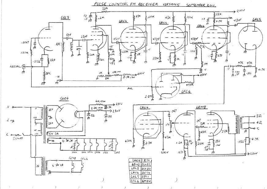
Circuit of the 5th Pulse Counting Receiver. This incorporates an
extra audio stage needed to drive the 6BM8 to full power. A magic eye simplifies
tuning.
| INPUT (uV) | AGC (V) | QUALITY |
| 2 | detectable | |
| 5 | -0.95 | noisy |
| 8 | slight noise | |
| 10 | -1.49 | |
| 12 | -1.7 | noise free |
| 20 | -2.44 | |
| 50 | -4 | |
| 100 | -5.55 | |
| 200 | -7.08 | |
| 500 | -8.84 | |
| 1000 | -9.93 | |
| 5000 | -12.24 | |
| 10000 | -19.8 | magic eye closed |
This table shows ACG voltage versus signal input. Frequency was 100Mc/s, deviation 50Kc/s, modulation 1Kc/s. 5K pot was adjusted for maximum sensitivity at the start of the test. Signal generator was a R&S SMS.
This is the best performer so far. It also includes the often asked for magic eye circuit. It follows the original circuit in that 6AU6's are used for the IF and limiter, but there is one less IF stage. This is because in the original receiver this contributed more noise than gain. If you think you're seeing 43K resistors in the circuit, you're right - they were to hand so were used. 47K is suitable instead.
This Pulse Counting Receiver was made by Josef from the Czech Republic.
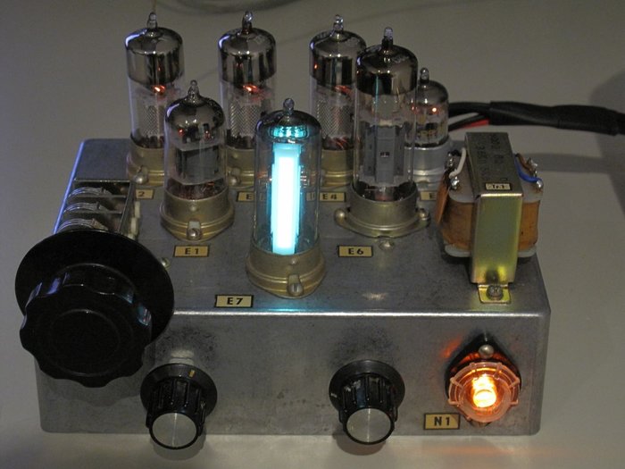
It uses the EF80 IF amplifier stage and
includes the EM84 magic eye. The power supply is external and connects
via an octal socket at the back.
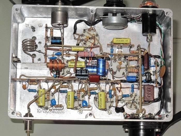
I thought this was a particularly good
example of correct construction technique. As can be seen, wiring is kept
short and direct. The aluminium diecast box makes an excellent chassis
for RF projects such as this. The particular box used was this http://www.tme.eu/cz/details/hm-1550we/univerzalni-krabicky/hammond/1550we/#.
You can see the YouTube video here https://www.youtube.com/watch?v=hZjDmox4QzA.
It gives a good idea as to how the receiver operates.