EA Stereo simulator tested with TDA7000 receiver. Results exceeded expectations.
EA Stereo simulator tested with TDA7000 receiver. Results exceeded
expectations.
With the discovery of the Philips TDA3810 stereo simulator IC, as part of my research into the TDA7000 FM receiver, interest had turned to stereo simulation in general. Some TDA3810 IC's had been ordered with the idea of testing one with a TDA7000, and if the results were good, to design and build a simulated stereo FM tuner.
In its most basic form, stereo simulation
can be obtained by feeding a mono signal into a speaker system where the
woofer and tweeter are physically some distance apart. The low frequency
sounds will emanate from around the woofer, and the high frequency sounds
around the tweeter. As the sound changes in frequency, it will appear to
move between one speaker and the other, and thus give a directional and
spatial effect.
More serious simulator designs use active
filters, and better still, delay circuits.
The resultant audio is not actually stereo
of course, since the separation between the left and right components is
lost when combined into a mono signal. Nevertheless, the effect is that
it sounds like stereo. For typical listening,
it is hard to pick the difference. Where it would be shown up is with program
material, where it is known that one channel should contain a particular
sound, or with anything specifically created to cause a directional effect.
Once upon a time, sound effects such as a steam train or a bouncing ping
pong ball were used to demonstrate stereo recordings. Such material will
obviously not produce the expected effect.
Despite that limitation, the sound is
much more pleasant and life-like than the 'hole in the wall' effect of
a single mono speaker.
EA "Stereo Synthesiser".
In September 1982, Electronics Australia
described a simulator circuit which was based around a Matsushita (National
Panasonic) MN3001 bucket brigade device. To my surprise, I discovered I
had a new old stock unbuilt kit for this project. Now was the ideal time
to try it out.
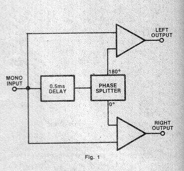
Basic concept.
The input is fed into the MN3001 which
provides a 500us delay. The output of this feeds a phase splitter. The
non-inverted output (i.e. the original phase) feeds the right output, along
with the original mono signal. The inverted output feeds the left output,
also along with the original mono signal.
At low (bass) frequencies, 500us is not
much of a delay, so the non inverted phase splitter output is largely in
phase with the original signal. Therefore, the right output is a fair replica
of the input signal. At the same time, the left output is minimal, because
of the inverted and original signal largely cancelling each other out.
The result is bass signals being 6dB louder in the right channel, and mostly
absent from the left.
If the input signal is raised to 1kHz,
the 500us delay becomes significant, since it is half the period. The two
phases are effectively reversed, so now the left channel contains most
of the output, and the right channel signal is largely cancelled. This
effect occurs at every 1kHz interval.
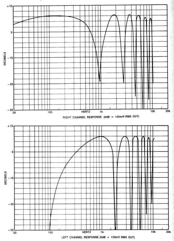
Frequency response of the circuit.
Note that the frequency response for each channel is the opposite to that of the other. Therefore, as the audio signal changes with frequency, it will appear to move from one speaker to the other.
The Circuit.
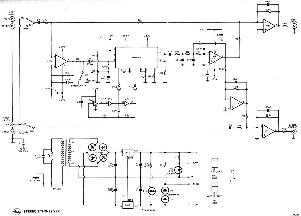
The input switching circuit allows for a stereo signal to pass through normally when required (e.g. an AM mono/FM stereo tuner signal source). For the purposes of stereo simulation, consider the wipers of S1a and S1b joined together, and fed from the mono signal. The mono signal thus proceeds to the inverting inputs of op-amps IC1a (left) and IC1c (right). Gain is one, which is set by the ratio of the 100k resistors. Note that the input 100k resistor for 1C1a consists of two 47k resistors in series. At this point, the left and right outputs would be a replica of the input signal (Both are actually inverted, but this makes no difference to overall operation).
The IC1b section of the LF347 operates as a driver for the following bucket brigade delay. Since its input is fed from the junction of the two 47k resistors referred to previously, the input amplitude is half that of the mono input signal. This op-amp is also wired for unity gain because of the two 100k resistors. The MN3001 is thus fed with half the input amplitude, to ensure the signal peaks within are below maximum. The MN3001 is a 512 stage bucket brigade device which creates the 500us delay. Its input bias is set by the 10k trimpot to -4.5V.
The 4049 operates as an oscillator for
the clock input of the MN3001, operating at 550kHz. Output from the MN3001
is fed into a low pass filter based around the TL071 op-amp. It also operates
with unity gain, and the -3dB frequency point is 20kHz.
From here, the in-phase (but delayed)
signal is fed to the inverting input of IC1a via the 27k resistor, which
is mixed with the mono signal to create the 'left' output. This in-phase
signal also feeds IC1d which operates as a unity gain inverter. Thus, its
output is now 180 degrees out of phase (and delayed), compared to the original
mono signal. Its output is fed into the inverting input of IC1c via another
27k resistor, and again mixed with the mono signal to create the 'right'
output. Note, of course, the 'left' and 'right' designations are purely
arbitrary and could be reversed.
When the stereo simulation is not required, the drive to the MN3001 is shorted to earth by S2. In this situation, there is no signal from the 27k resistors. The mono signal proceeds through IC1a and IC1c without anything being added to it.
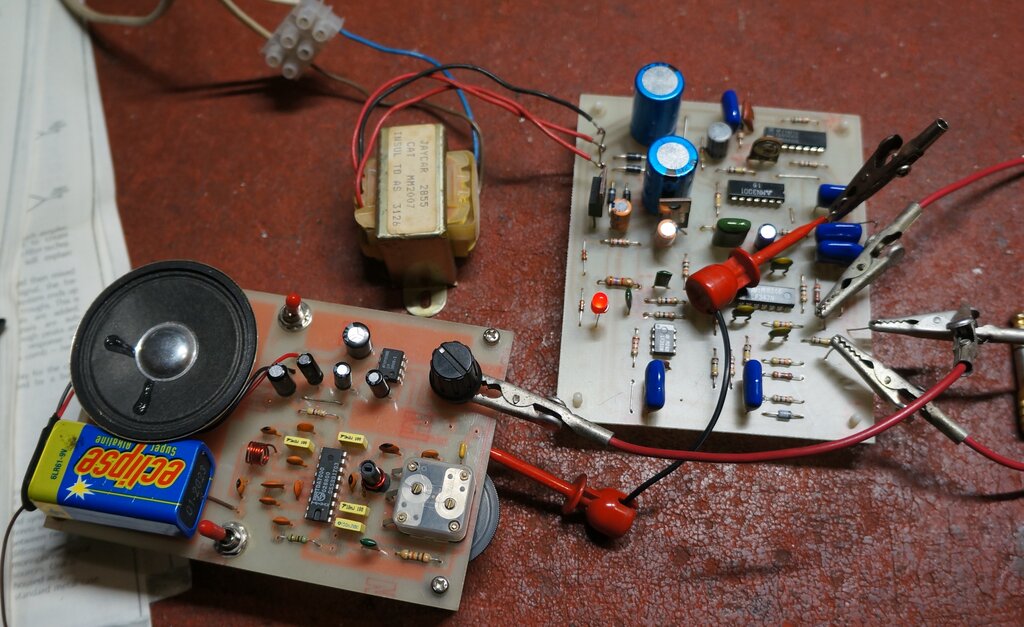
Construction.
The kit was old Jaycar stock from around
the time the magazine article appeared. It was a short form kit; i.e. no
cabinet, transformer, or hardware supplied. As was usual back then, the
instructions were simply photocopied from the EA article, with a separate
page noting component substitutions. Fortunately, all the parts, particularly
the MN3001 was present. However, the two 390R resistors were incorrectly
substituted with 390k. There was also an additional 0.1uF capacitor which
had found its way into the packet of parts.
Unfortunately, 40 odd years had taken
its toll on the PCB. Although the tracks were all tinned, they were tarnished
and difficult to solder to, even when scraped and cleaned. With the amount
of connections, I was quite worried about the possibility of dry joints.
Construction took longer than it otherwise would have, because of having
to clean each individual connection before soldering. Fortunately, it did
work on first power up.
For anyone wanting to duplicate the above circuit, the only challenge in the modern day is obtaining the MN3001. It is obsolete, and unfortunately the guitar amplifier crowd have pushed up the price to absurd levels, because it can be used in reverb circuits. The MN3001 is still listed by some suppliers, and it is essential to shop around for the best price. The MN3001 is a dual bucket brigade device, but only one channel is used in this circuit. Therefore, it should be possible to use the single channel MN3002 instead.
Performance.
I used a TDA7000
FM receiver as a signal source, and a radio cassette recorder with
line inputs for the audio amplifier. I wasn't really sure what to expect,
but the results were astounding. The effect is as good as 'real' stereo,
with very obvious separation between the channels.
In fact, as far as FM stereo is concerned,
it can actually be better. The reason for this is that some stations blend
the left and right channels to some degree, in an effort to improve signal
to noise ratio. As is well known, the pilot tone system used for FM stereo
has poor performance on weak signals. In stereo mode, there will be noise
present with weak signals, which are still strong enough to provide noise
free mono reception.
For most program material, it is very difficult
to tell the difference between real and simulated stereo. A test was done
to compare this. The TDA7000 receiver, and the stereo FM tuner in the radio
cassette recorder were tuned to the same station. By switching between
the line input (simulated stereo) and the FM tuner (real stereo), the signal
was immediately comparable. The particular station being received did not
appear to blend the left and right channels, and had good separation. Switching
between the two, the spatial effect was very similar. The noticeable difference
is to do with the directional effect, which is not surprisingly much more
random, since it is frequency dependent. Nevertheless, certain musical
instruments do favour one channel, giving a very realistic effect.
It must be emphasised that it was only
by doing this direct comparison that the difference could be noticed.
In short, the simulator circuit provides
the same improvement to listening pleasure as real stereo. Switching between
mono and simulated stereo is like night and day. The 'hole in the wall'
effect of mono is very obvious in comparison. The only limitation
I can see is where the left and right channels of the original sound must
be represented as such to the listener. For typical radio program material
this would hardly ever exist. And in any case, it is still far better than
a mono signal. Similarly excellent results were had with a ZN414
receiver.
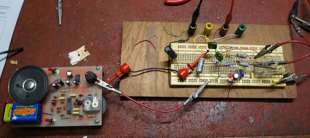
Test set up with TDA7000 receiver and TDA3810 stereo simulator.
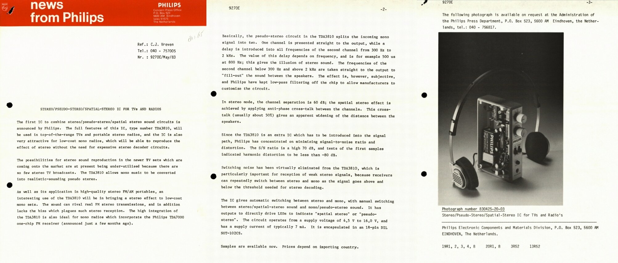
In 1983, Philips released the TDA3810 "Spatial, stereo and pseudo-stereo sound circuit" IC. This IC was intended to add extra separation to a stereo signal, or to simulate a stereo signal from a mono one. Increasing stereo separation is useful for applications where the speakers are close together, such as a television or portable radio. In fact one of my televisions (Philips 2BS chassis) does include a TDA3810 in the audio circuit, so I was already aware of the improved spatial effect available.

An important point to note is that there
is apparently an error with the original Philips data, in that pins 3 and
5 are reversed. This has been mentioned on another site here http://www.geocities.ws/podernixie/audio/tda3810-en.html
The following Valvo and Elektor diagrams
are correct.
Unlike the MN3001 circuit, the TDA3810 uses frequency selective filters to create the two channels. The mono input is fed to the 'right' channel as is. However, for the 'left' channel, the signal between 300Hz and 2kHz is delayed depending on frequency. At 800Hz, the delay is 500us. This is achieved by a "Twin T" filter. Frequencies outside 300Hz to 2kHz are fed to the left channel output without alteration. Therefore, the stereo effect is produced only by the frequencies in that pass band; the rest of it being mono.
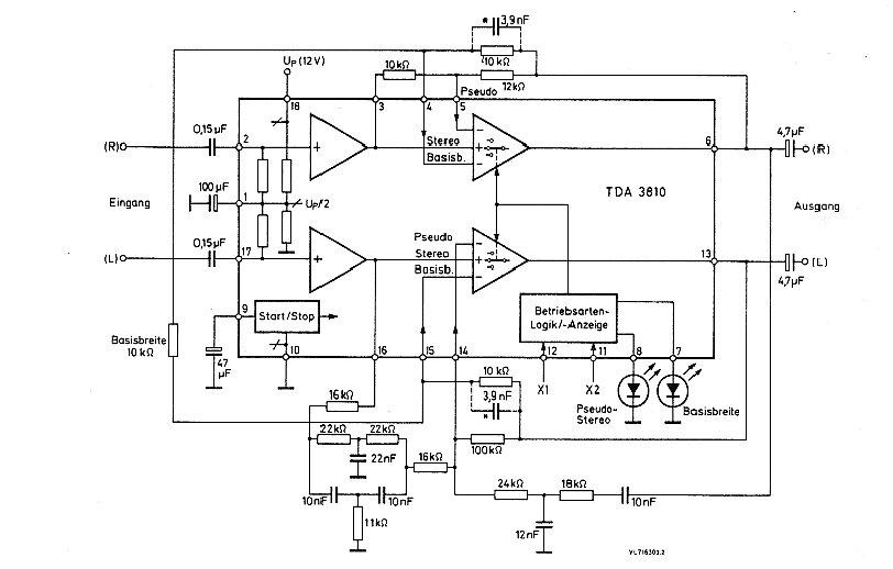
Block diagram of the TDA3810 from Valvo. This version is easier
to understand than that provided by Philips.
When used as a mono to stereo simulator,
the left and right inputs are connected together and fed with the mono
signal.
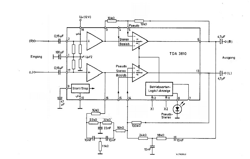
Further simplified, this diagram shows only the stereo simulator
components. Pin 12 must be always earthed, and when simulation is required,
pin 11 also earthed.
Elektor had designed an add-on stereo simulator
for their TDA7000 FM receiver project, and this part of the circuit is
shown below.
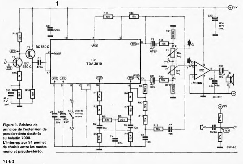
Elektor circuit for use with the TDA7000.
Test Circuit.
It was noted that there were some differences
in component values between the Philips, Valvo, and Elektor circuits. It
appears that Elektor used the Valvo data since their circuit uses the same
component values. The differences would be a slight gain change in the
right channel, and a slightly different frequency response for the filter
in the left channel. Either way, construction is a bit messy because of
the non preferred value resistors, which means using two resistors to make
up the required value.
The Elektor circuit shows a two transistor
pre-amplifier for use with their previous TDA7000 receiver project. Also
noted was the output voltage dividers R19/R21 and R20/R22. Why step up
the input signal amplitude in the first place, when it only has to be attenuated
afterwards?
I thought it odd that the TDA3810 should
require a certain minimum signal level. There was nothing in the data to
indicate that - only that the input should not exceed 2V rms. And, it would
be illogical anyway. Such is the nature of audio signals that they will
get to zero amplitude at some point. Furthermore, with Philips' intention
of using this IC with the TDA7000, it would seem strange that it would
require additional amplifier components - especially where space is limited
as in a pocket receiver.
I am almost inclined to believe that the
designer of the Elektor circuit assumed the input needed to be 2V rms,
rather than that being the maximum.
My test would be to build the circuit,
and see how it worked connected directly to the TDA7000, only adding the
preamplifier if necessary. As it turned out, the preamplifier components
used by Elektor were unnecessary, which simplifies construction somewhat.
Referring to the Elektor circuit above,
C1 was connected to the 18k load resistor at pin 2 of the TDA7000. C1 does
not need to be as high as the 0.47uF specified. 0.1uF is quite adequate
with good bass response.
In turn, with the pre-amp not included,
the output voltage dividers are no longer required (R19 to R22). The outputs
of C9 and C11 can proceed straight to the volume control and following
amplifier.
Note that the two inputs at pins 2 and 17 are connected directly together. This saves an extra coupling capacitor. This connection is permissible since the bias circuits for each input are identical. Incidentally, the input resistance is 75k for each channel. Separate input capacitors were tried but with no detectable difference.
Although it was never intended, it was possible to drive headphones from the output of the TDA3810 at reasonable volume. I mention that as a quick way to test the circuit, rather than a normal mode of operation. The low impedance loading could affect operation because the filter inputs are taken from the outputs. The data specifies a minimum load resistance of 4.7k.
For the audio amplifier, the Elektor circuit uses two LM386's; one which is already present in the receiver to be modified. In the modern day, a dual audio amplifier IC like the TDA2822 would be more appropriate, where space is important.
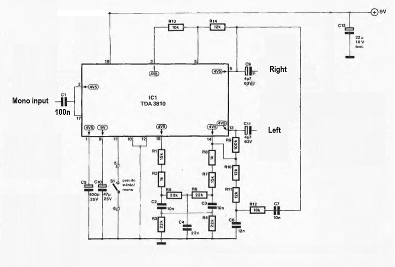
Test circuit used with TDA7000.
When pin 11 is earthed, the circuit reverts
to mono. If a LED is connected between pin 8 and earth, it will indicate
the mono/psuedo-stereo status. A resistor for the LED is not required.
C12 is the usual supply decoupler and is not critical. Nor does it need
to be a tantalum as shown.
In view of the output load specifications,
the volume control can be a common 10k-50k stereo type. It is an interesting
thought to instead control the volume at the input of the TDA3810, since
this would require only a single gang potentiometer.
The disadvantage would be a poor signal
to noise ratio at low volume, because the following circuit would be always
operating at full gain. Nevertheless, it was tried and did work, in that
the stereo effect remained constant, but hum was evident at low volume.
Quite possibly, with care taken with layout and construction, it could
be done. It would still be doubtful for any hi-fi application.
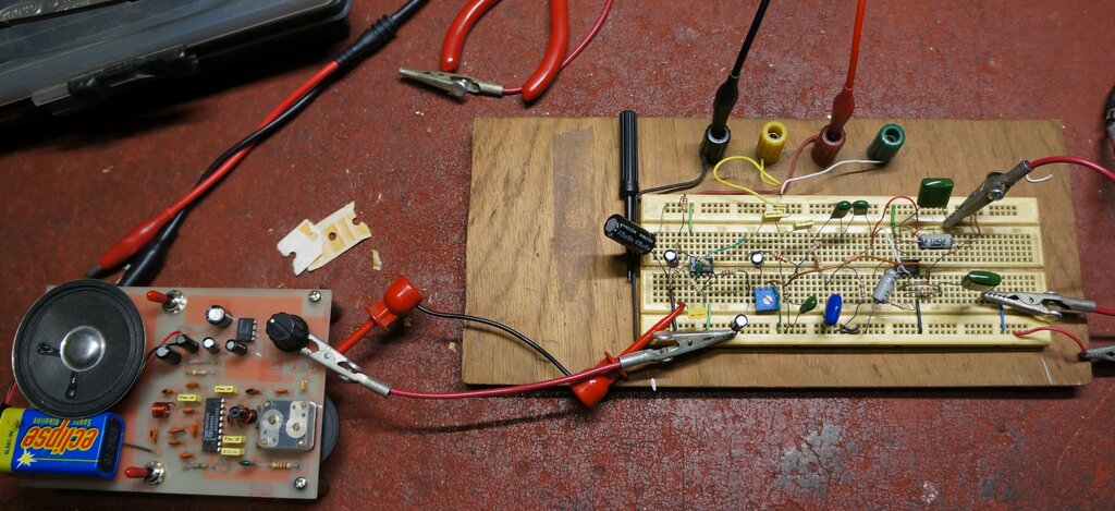
Performance.
After the usual faults which always occur
when assembling circuits on a solderless breadboard, I was pleasantly surprised
to hear the results. It certainly works, and very well at that.
How does it compare with the EA September
1982 circuit, which is after all, more complicated? In terms of the spatial
separation, the circuits are much the same. My subjective opinion is that
the directional effect is less with the TDA3810, but this is to be expected
with
the much simpler filtering. And, it is only because I listened to both
circuits looking for it, that I could make this comparison.
However, when it comes down to it, the spatial effect is more important (and more obvious), so for general listening, the TDA3810 does the job very well. It's also a lot cheaper (and more widely available) than the MN3001. It would be possible to make an excellent portable radio with a TDA7000 (maybe a ZN414 as well), a TDA3810, and a TDA2822. Without any doubt, the simulated stereo from the TDA3810 is much more enjoyable and relaxing to listen to, than the original mono signal. Again, as with the MN3001 circuit, most listeners would assume the stereo is real, unless told otherwise.
EA April 1983 Stereo Simulator.
Based around simple op-amp circuits, this provides excellent performance.
After presenting their bucket brigade device
based simulator in September 1982, Electronics Australia came up with another
design, in April 1983. This was intended to be a simpler, more inexpensive
design, but also one which took up less space, since it had been intended
to fit into a previous AM tuner project.
The new design operates along similar
lines to the TDA3810, in that it is op-amp and filter based.
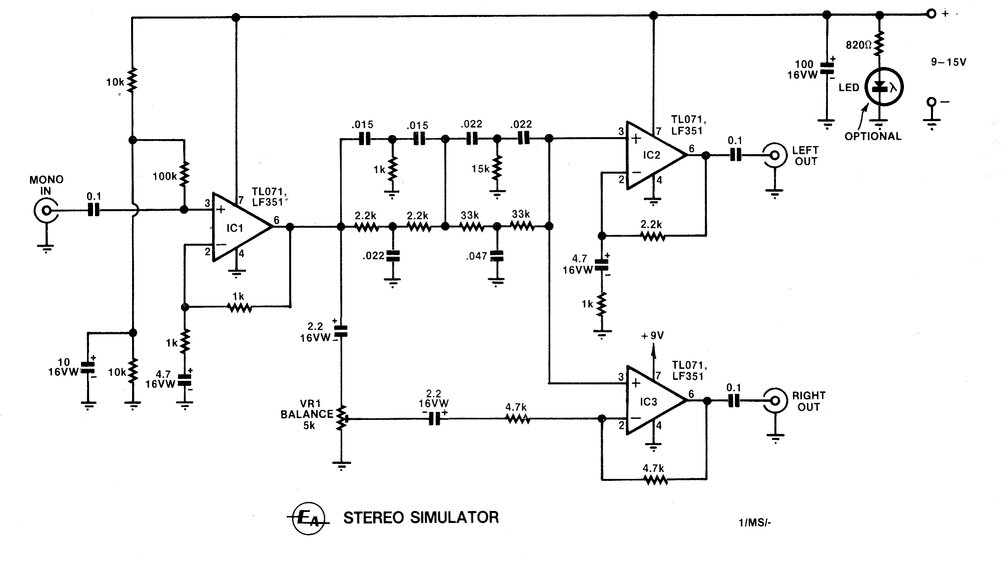
Circuit of the April 1983 stereo simulator.
The Circuit.
The mono input is fed into IC1 which is
simply a unity gain buffer, to isolate the following filter circuit from
the unpredictable signal source characteristics. The output splits into
two paths. One feeds a Twin T filter which creates a notch in the frequency
response at 200Hz and 5kHz. This is shown by the dotted line in the response
graph below.
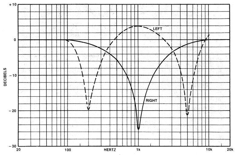
Frequency response of simulator.
The output from the filter proceeds to IC2, which has a gain of slightly more than two (to compensate for filter loss), and this feeds the 'left' output. The other signal path from IC1's output feeds IC3, which functions as a differential amplifier, and produces the 'right' output. The signal from the filter is fed into the non-inverting input, and the original mono signal is fed into the inverting input, via preset pot VR1. IC3's output is therefore the difference between the filtered and mono input signals. Since the filter response peaks at 1kHz, when this is subtracted from the mono signal, the result is a notch, also at 1kHz. VR1 adjusts the gain of IC3 so that the left and right channels appear to have the same overall amplitude. That is, it functions as a balance control.
One again, like the TDA3810, we can see that as the frequency content of the signal changes, it will appear to move between the two channels.
Constructing and Testing.
Aside from the filter circuit, the capacitor
values are not hugely critical. The op-amp circuits are otherwise very
standard. Since the supply is a single positive rail, the op-amps need
to be biassed to their half way point, and this is done with the voltage
divider at the non-inverting input of IC1. As IC1's output is DC coupled
to the other two op-amp inputs, these are also biassed to the half way
point and don't require separate voltage dividers.
With parts to hand, I constructed the
circuit using one half of an LF353 for IC1. I used a 10k trimpot for VR1.
Some of the electrolytic capacitors differed in value, but again these
are not critical.
The circuit worked straight away, and
the performance was again a surprise. I used LF351's for IC2 and IC3, but
later tried replacing them with a single LF353, reducing the IC count by
one. This could be worthwhile where space is important in a portable radio
for example.
Presumably, a quad op-amp could get the
IC count down to one for the whole thing, but did not try this. Physical
layout is actually a lot easier with separate IC's, especially when building
the circuit on a breadboard.
Performance.
Despite its apparent simplicity, this
circuit provides excellent results. The directional performance seems to
be superior to the TDA3810, which is perhaps not surprising, given
the more complex filter used in the EA circuit. One test I did with the
EA and the TDA3810 circuit was to sweep a signal generator over the audio
pass band, to test for the directional qualities. As the frequency was
increased, the tone could be heard changing from one channel to the other.
The effect was more noticeable in the EA circuit.
Perhaps it was due to the program material
I was listening to at the time, but I sensed that performance was slightly
better with separate LF351's for IC2 and IC3, than it was when I used the
dual LF353. Also, I felt the balance control didn't have quite enough adjustment.
It was already at full gain, and I sensed it could do with a little more.
This would be likely due to having used a 10k pot for VR1 rather than the
specified 5k. With the higher resistance pot, the ratio of the two 4.7k
feedback resistors changes. To this effect, reducing the 4.7k between pin
2 of IC3 and the 2.2uF gave a better range of adjustment. Alternatively,
the circuit could be simplified by replacing the 4.7k with the 10k trimpot
, and doing away with VR1 and one of the 2.2uF capacitors altogether. It
certainly seemed to work when I tried it.
In conclusion, the three circuits in order
of overall quality would be; 1) the EA September 82 circuit, 2) the EA
April 83 circuit, and 3) the TDA3810. All of them give a good spatial effect,
and the difference seems to be with the how good the directional qualities
are.
As to which to choose, that will really
depend on the application, how much one wants to spend, and the space available
for the circuit. It would be hard to justify the MN3001 circuit for a portable
radio, but it would be ideal for a home set up. For a pocket size TDA7000
or ZN414 receiver, the TDA3810 would be a good choice.
Stereo simulation opens up new possibilities. For FM receivers, we can see that by working with a mono signal instead, and simulating stereo from it, we can have noise free 'stereo' at much weaker signal levels. Another advantage is with FM receivers which do not have enough bandwidth for the stereo signal. Typical of these would be receivers using the TDA7000, super-regenerative, or pulse counting circuits. It is also a good way out of the problem of what to do about lack of AM stereo in the modern day.
Use with Valves.
The EA April 1983 circuit should be adaptable
to for use with a valve signal source. Since the input op-amp is a FET
type, simply increasing the 100k bias resistor at pin 3 to 470k or 1M,
should allow good matching.
As to actually making a stereo simulator
with valves, the circuit to adapt would be the EA April 1983 design. The
input op-amp could be replaced by a dual triode; one stage providing some
gain, and the other being a cathode follower to drive the filter. IC2 could
be substituted with a single triode at its simplest, or again a dual triode
with cathode follower output, to avoid the following stage affecting the
gain. IC3 would require another dual triode functioning as a differential
amplifier, and again, maybe a cathode follower output stage.
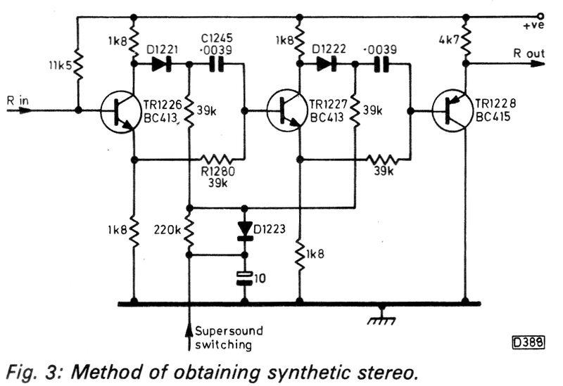
The July 1982 issue of "Television" describes
the audio processing for the stereo versions of the Thorn TX9 and TX10
chassis. The feature of interest here is the stereo simulator; the circuit
of which is shown above. Thorn have named it "Supersound". The signal forming
the left channel is actually the original mono signal. Only the right channel
is synthesised.
The signal is fed through two frequency
dependent phase delays. The phase shift is about 180 degrees at 1kHz, which
increases to 360 degrees with increasing frequency. This introduces a delay
in the right channel, and since the delay is frequency dependent, the spatial
effect changes with the audio content.
The first two transistors are wired as
phase splitters - note the equal collector and emitter loads. At low frequencies
the .0039uF capacitors have a high reactance, so most of the signal is
from the emitters via the 39k resistors. We can see at low frequencies,
that the audio is effectively passing through two emitter followers, in
phase with the original signal. In effect, nothing happens to the audio,
and the left and right outputs are the same.
However, as the frequency rises, the reactance
of the .0039uF decreases, so more of the audio signal is taken from the
collectors, which are of course 180 out of phase with the input signal.
The third transistor is simply an emitter
follower buffer and does not perform part of the actual simulation circuit.
The input biassing would need to be altered
to use this circuit as a stand alone simulator. The 11.5k needs to be increased;
probably to something like 100k, and another resistor added from the base
to earth. Its value should be such that the 1.8k resistors drop about one
third of the supply voltage. Input and output isolating capacitors would
also be required.
No mention of the supply voltage is given.
It looks like the circuit would probably work on 12V. The diodes are only
for switching. When biassed on, the simulator is active. If the circuit
is built as a stand alone unit, the diodes D1221 and D1222 can be bridged
out, and their associated 39k bias resistors removed. The 220k, D1223,
and the 10uF then become superfluous.
Note that this circuit has not been tested.
The simplicity would be attractive in duplicating this circuit to work
with valves.
