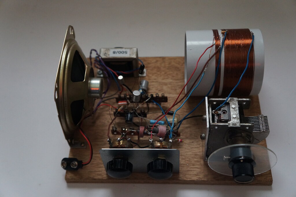
One Transistor Reflex Receiver with the constructed version having two extra transistors for speaker reception.
One Transistor Reflex Receiver with the constructed version having
two extra transistors for speaker reception.
This reflex receiver was presented in the
June 1963 issue of Radio, Television & Hobbies. Great claims were made
as to its performance, apparently providing good headphone volume with
no aerial connection from local stations.
In more recent times, the project was
described in the HRSA "Radio Waves" magazine for April 2006, with a further
update in July 2006.
Transistor reflex receivers have been
described in the article
here, which explains the background of this interesting design.
The Circuit and Operation.
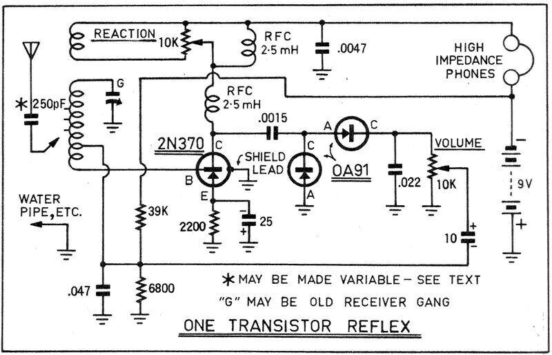
The incoming signal developed across the
tuned circuit feeds the base of the transistor. This is done from a tapping
on the coil due to the low input resistance of the transistor, and is standard
practice. At this point, the transistor operates as an RF amplifier, with
an amplified version of the signal appearing at the collector, developed
across the 2.5mH RF choke. This is then demodulated by the two 0A91 diodes,
configured in a voltage doubler circuit. This provides slightly more audio
signal than a single diode.
The 10k volume control provides the load
for the detector, with the .022uF filtering out the remaining RF.
The transistor is biassed with a voltage
divider consisting of the 39k and 6.8k resistors, and the 2.2k emitter
resistor provides stabilisation. The 25uF capacitor prevents loss of signal
across this resistor.
At this point, the audio developed across
the volume control could be fed into an amplifier or headphones, allowing
the signal to be heard. However, the reflex circuit goes one step further,
and the transistor which amplifies the RF is now used to amplify the audio
at the same time.
By following the path of the audio signal,
it can be seen that it is introduced into the base of the transistor via
the tuned circuit. The tuned circuit has no effect on the audio signal,
since the few turns of wire has insignificant inductance at audio frequencies.
A stronger audio signal is now present
at the collector, but this time the 2.5mH choke has little effect, since
again the inductance is too low to affect the low frequency signal. Instead,
the signal now appears across the headphones which are also in the collector
circuit.
When the transistor amplifies RF, the
.0047uF prevents signal being lost across the headphones, yet the reactance
of this capacitor is such that audio signals pass unimpeded.
Effectively, the circuit performs as though it had two transistors, although only one is used. This is possible because it's a simple matter to keep the two frequencies separate. At one end is the audio signal, extending to about 10kHz, and at the other is the RF covering 550 - 1600kHz.
While the circuit will work as described
for local station reception, a huge improvement can be made by including
regeneration or "reaction". This is the purpose of the extra winding coupled
to the tuned circuit. It provides positive feedback, so that the RF signal
is amplified many times over. If left uncontrolled, the signal level builds
up to the point where the circuit oscillates. In this form it is useless
for reception, and radiates interference. If the feedback is controlled
so that the level is just before the circuit oscillates, a tremendous increase
in gain occurs, and sensitivity similar to a multi-stage superhet is possible.
This is the purpose of the 10k pot - it
allows the feedback to be adjusted. The 2.5mH choke across the pot prevents
loss of DC voltage and audio signal, particularly with the pot wiper towards
the centre of the track.
The tuned circuit is an air cored type, although a description was given for using a ferrite loopstick. If required, an external aerial could be connected into the tuned circuit via a 250pF capacitor.
Building the Reflex One.
This is another of those RTV&H projects
that I'd read about again and again for years, and come late 2019, decided
to actually build it! I recalled that the HRSA Radio Waves magazine had
also presented the project, and so found the article to see what their
conclusion about the design was. Again, it was supposedly a very good performer,
receiving interstate stations with no aerial. Their version was essentially
that as presented originally by RTV&H, but the aerial coil had been
mounted horizontally. It's a curious thing why this was not done in the
original design, because so doing actually allows it to function as a loop
aerial, avoiding the need for an external aerial in most situations.
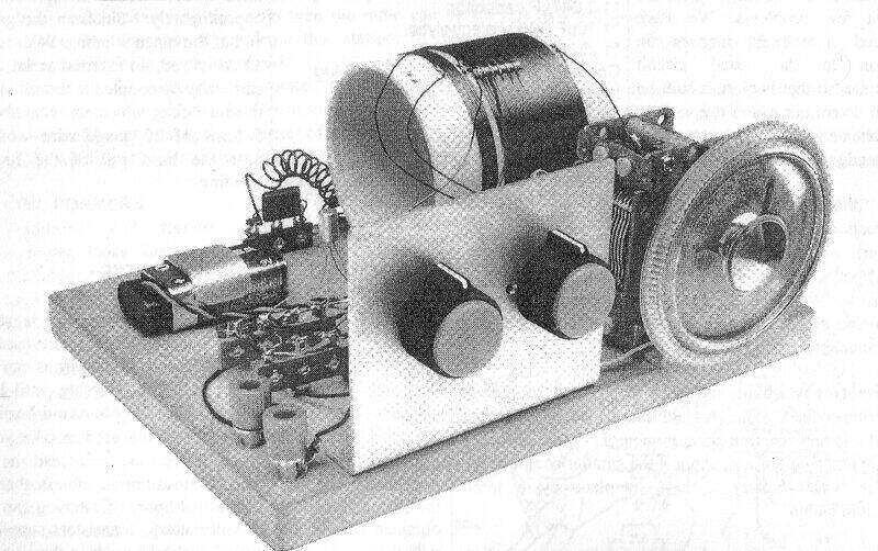
As presented by the HRSA. Note the horizontally mounted aerial coil.
Otherwise, the design is the same as the original.
My attempt would be to follow the same
layout as the original, but as per the HRSA version, mount the aerial coil
horizontally. It seemed pointless to require an external aerial connection
when it could so easily be avoided.
A number of transistor types were suggested,
all of the germanium "drift" type. These have higher gain than old types
like OC44, etc. As it happened, I had a number of Tektronix spare parts
transistors, 2N1517. These, it turned out were simply a rebadge of the
Philips OC171. In fact, "Made in Holland" is printed on the casing, confirming
the Philips origin. I also have other suitable types, such as AF117, which
is what the HRSA version used, but chose the 2N1517/OC171.
A suitable variable condenser was found;
a type incorporating a reduction drive, and a suitable dial and mounting
bracket were made up. For the coil, I used a 65mm pipe joiner as per the
HRSA design, found some likely looking copper wire, and wound up the coil
to specs. (55 turns tapped at 2,3, and 5 turns, and the reaction winding
5 turns [not actually specified, but apparently 24 B&S gauge]).
A piece of plywood was found already cut
to the 6" x 8" specification on which to mount all the components. Since
the design required high impedance headphones, I instead use a transformer
to feed modern low impedance phones.
Not As It Should Be.
Once the set was finished and powered
up, it produced signals as per other reflex designs I've experienced. In
particular, the Sydney ABC stations (576kHz, 630kHz, 702kHz) with their
high power came in very well with good volume. Alas, all was not well with
the regeneration. It refused to work when the set was tuned above 2BL (702kHz).
Thinking that there might not be enough regeneration turns on the coil,
I then substituted a ferrite loopstick, since it would be easier to experiment
with the number of turns. This too achieved nothing.
It was certainly at odds with both the
RTV&H and HRSA articles. I briefly tried another type of regeneration
circuit, whereby a small amount of capacitance is used to couple the RF
from the regeneration pot wiper to the top end of the tuning circuit. This
did work, and proved the tuning coil covered the correct frequency range,
and was capable of oscillating. However, I was loathe to change the circuit
- it would simply be masking some unknown fault, and it wouldn't be the
"Reflex One" any more.
I put the set aside for quite a while
and thought about it. Why was there not enough feedback?
RF Choke.
A little thought provided the answer.
If we look at the regeneration circuit, we can see the feedback coil is
in the collector circuit, which also has the RF choke that feeds the detector
in series with it. This means that some of the RF voltage appears across
the choke, and some across the regeneration coil. It can be imagined that
if the choke had a much higher reactance than the regeneration coil, then
most of the RF voltage would appear across it, and not the regeneration
winding.
And so it turned out to be. By reducing
the choke inductance, the regeneration worked, and worked very well. The
trade off might be that the detector would then receive less input, so
the idea would have to be a compromise. As can be seen, the choke specified
is 2.5mH. I tried 680uH with quite good results, providing sufficient volume
and good regeneration. Going up in value I then tried 1mH, still with excellent
regeneration. I didn't have anything between 1mH and 2.5mH, so left it
at that.
What has me curious is has anyone else
who constructed the set had this problem? My layout is the same as the
prototype sets, so any stray coupling which might affect regeneration should
be the same. As far as I could tell, the choke I used was the same type
in the prototype, and I even measured the value to be sure it was correct.
Yet, it simply robbed the regeneration circuit of too much current!
The answer may never be fully known, but
the important thing is the set is still schematically the same, albeit
with a change in one of the chokes. Furthermore, it works as it should.
With headphones, reasonable volume was
obtained from the Sydney commercial stations, and very good volume from
the three ABC stations. At my location, the volume control was not required
since the signal was never too loud. The regeneration control was very
smooth with no backlash at all. I found that the optimum output transformer
impedance feeding the headphones was 2 to 5k.
It was noted that a commercially made
loopstick wound with Litz wire provided more signal than the air cored
coil. No attempt was made to measure the difference, but at a guess would
have been about 3dB. Therefore, the recommendation is, unless it's desired
to keep to the original design, a ferrite loopstick is to be preferred.
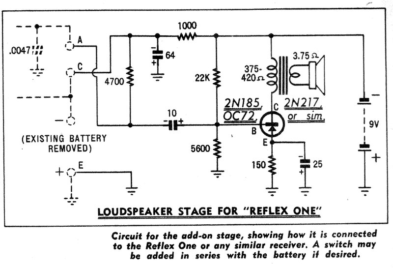
Loudspeaker Reception.
A subsequent article in RTV&H for
August 1963 showed how another transistor could be added for speaker reception.
Given my location being weak for the commercial
stations, and that headphone use was limiting anyway, I proceeded with
adding a speaker. As can be seen, the circuit is that of a single transistor
class A amplifier. In place of the headphones is a 4.7k resistor. I considered
that transformer coupling might provide a stronger signal, since the winding
resistance would drop much less of the supply voltage to the RF transistor.
The circuit was built up on a breadboard and tested, using an AC128 transistor.
There wasn't as much difference between the two as expected, but nevertheless
was noticeable. Again, maybe around 3dB at a guess. I used a transistor
interstage transformer which is specifically designed for this kind of
work.
Unfortunately, while a speaker could now
be driven, it was just too weak except for the strong ABC stations. This
isn't meant to be a criticism of the circuit, since it was designed in
a part of Sydney which does have a high field strength, and no doubt would
provide acceptable reception. In fact, performance was like any other two
transistor reflex set with regeneration.
Two Transistor Amplifier.
It was obvious that for the radio to be
practical in my location that a one transistor audio stage was never going
to be enough, even with transformer coupling. Thoughts turned to two transistors.
RTV&H had a two transistor direct coupled amplifier circuit which had
been used in a number of projects over the years. It was apparently developed
by STC, and was designed with good thermal stability in mind - important
with germanium transistors. I had used this amplifier circuit previously
in other projects, so knew of its capabilities. In short, I felt it would
suit the Reflex One.
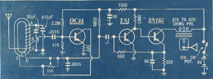
Three transistor regenerative circuit from March 1959 was the first
to use the STC amplifier design.
The amplifier is based around the TS1 and
2N185 transistors. Bias stabilisation comes about from the current flowing
in the output transistor. If the current increases, then the voltage across
the 220R also increases. Current through the 68k also increases, causing
the TS1 to conduct more. Since the base of the 2N185 is directly coupled
to the collector of the TS1, as collector voltage of the TS1 falls, so
does the bias of the 2N185, restoring correct operating conditions. To
cater for different transistors, the 68k can be altered so that the output
transistor operates with the correct bias.
In my construction of this amplifier,
I used an OC71 and AC128 since I have a good quantity of these. Initially,
I tried an AC128 for the first transistor, but although it worked, the
output transistor was not biassed correctly. Current was much less than
it should be. While it's possible altering the 68k may have improved it,
it was easy to try an OC71, and given how good it was, left it as is. The
output transformer I used was a 500R to 8R type.
Again, both transformer and resistance
coupling were tried, in terms of connecting the amplifier to the receiver,
with a similar change in gain. Given the ample sensitivity of the two transistor
circuit, it was felt more in keeping with the original by using resistance
coupling.
With the amplifier found to be successful,
it was built up on tagstrip, and the speaker and transformer were mounted
on the plywood base.
Final Circuit.
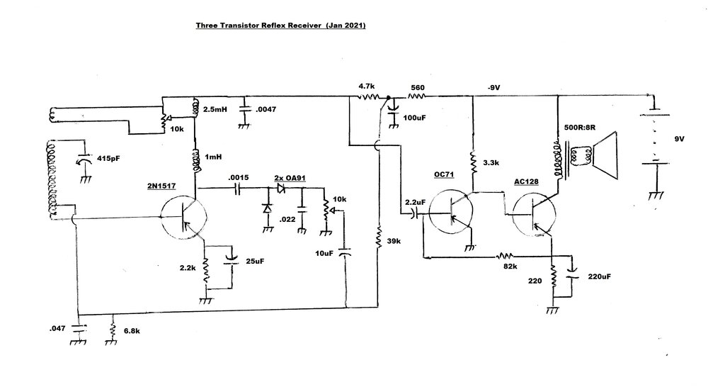
Reflex One with two transistor amplifier.
Current draw at 9V is about 16mA. Note that since PNP transistors are used that the supply is negative. The receiver works well at my location in the Blue Mountains. It's possible to receive 2LT clearly; a station about 60km distant but with the signal directed away. It's always a good daytime test for MW receiver sensitivity. Thoughts are to build the receiver in a cabinet making it a more practical unit as a portable. Performance is certainly good enough, and the controls are easy to adjust.