Gakken is a name familiar to me, as it
was their "Denshi Block" SR3A electronics kit given to me in 1976 which
did a lot for my electronics knowledge. It was with this kit I first constructed
simple transistor amplifiers and radios, with a few novelty circuits as
well. This kit was the predecessor to the more well known EX150 of more
recent times.
In recent years they seem to have re emerged
with a line of very interesting kits, some electronic, and some mechanical.
Readers of this site would be mostly interested in the little valve amplifier,
the radio kits, and the acoustic gramophones. These are well known to those
who trawl eBay, and there's a lot of sites related to them - mainly describing
what the author thought of constructing them.
There's little technical information however,
so this article will make up for that. First, put "gakken vacuum tube radio"
into your search. It is worthwhile searching the Japanese sites via http://www.google.co.jp,
seeing as they are of Japanese origin. I've built both the one valve variometer
tuned set, and the three valve regenerative set. Apparently, the valves
used are old stock Chinese valves. They have unusual type numbers, but
are directly equivalent to the usual RMA and European 7 pin battery valves.
HT supply in both kits is from series connected 9V batteries, while the
heater supply is a single C cell.
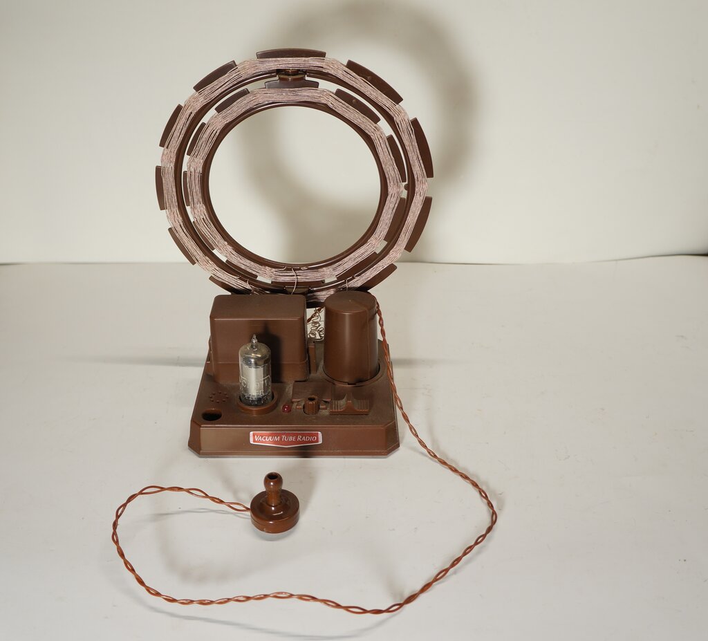
Variometer Tuned Receiver.
I bought this kit, late February, 2011.
The way it was presented is certainly very Japanese, and for US$39 was
excellent value. The receiver comes in a box dimensioned like that of a
large book, and the instructions come in a bound magazine. It's a very
professional job and the detail gone into is quite considerable. I have
never seen a set of kit instructions so detailed with regards to how the
receiver works. It goes into some detail about the variometer tuning, even
providing mathematical formulas. Perhaps it's because the Japanese aren't
into being dumbed down like the rest of the world. Most kit instructions
I've seen tell very little of the circuit design.
The construction of this kit is very easy.
All it basically entails is winding the two coils and connecting them to
the PCB under the plastic chassis. There is some minor assembly putting
in a few self tapping screws. I was mainly interested in the technical
aspects however, which is why I bought it, and here I was quite surprised
at what I found.
I had assumed, after building the three
valve set a few years ago, that this set would use a pentode (1T4 or equivalent)
as a regenerative detector. Not so!
The circuit.
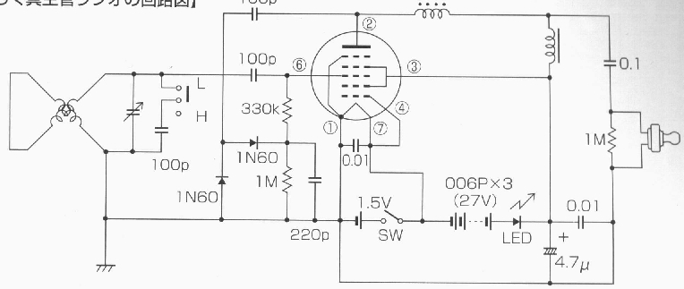
The tuned circuit feeds a reflexed RF/AF amplifier without regeneration.
It's a reflex circuit without regeneration,
which is a very Japanese thing. Look at any simple transistor radio, or
electronics kit designs, from Japan in the 1960's and you'll see reflex
circuits everywhere.
They are the basis of those two transistor
"Boys Radio" designs popular in the U.S. Performance with them is generally
good, but by adding regeneration you'll get something very similar to superhet
performance. Without regeneration, they are only good for local reception.
The idea is to amplify the incoming RF, detect it, then send the resultant
audio back into the valve to be amplified further. The one valve or transistor
functions both as an RF and AF amplifier.
First, let's look at the tuned circuit.
With the two coils in series it is possible to change the inductance by
swinging one through 90 degrees to the other. Inductance decreases with
the coils further apart. This inductance in conjunction with the variable
capacitor (according to the book it's 100pF) and optional 100pF is what
determines the tuned frequency.
As the range of inductance is insufficient
to cover the whole broadcast band, an extra 100pF can be switched across
the coil to receive stations at the low frequency end.
With the coils 90 degrees to each other,
the 100pF switched out, and the variable capacitor at minimum it tunes
to about 1600Kc/s. With the coils parallel and maximum capacitance, it
tunes to about 550Kc/s.
Reflexing.
This is the process of using one amplifier
for both RF and AF. As the two bands of frequencies are so far apart we
can amplify both with the one valve, without any significant reaction between
the two. Incoming RF is fed into the grid with an amplified signal present
at the plate; it's developed across the RF choke. The amplified RF is fed
via a 100pF to a voltage doubling detector using germanium diodes. The
diode load and RF filter is formed by the 1M and 220pF. At this point the
audio signal becomes available. So far, the description applies to any
RF stage feeding a detector, and indeed a simple receiver can be made thus.
However, we can 're use' the amplifier valve for the audio signal as well.
So, into the grid it goes via the 330K isolating resistor. This resistor
prevents the incoming RF from the aerial coil being shunted to earth by
the detector circuit, and in particular the 220pF. Yet, it allows the audio
to flow into the grid unimpeded. The RF choke has little effect at audio,
so can be regarded as a short circuit. However, the audio choke has a high
impedance and it's this which allows the amplified audio to appear at the
plate. The signal is fed to a piezoelectric earphone, via a .1uF and 1M
to eliminate any DC being applied.
A red led shows HT current is flowing
and acts as a power on indicator (the valve filament is not really visible).
The heater current comes from a C cell in a bayonet fit cylindrical holder
above the chassis - power switching is achieved by rotating the enclosure
so the contacts touch or break as required.
Pentagrid valve.
The most bizarre thing which I didn't
notice at first, is they've used a pentagrid valve wired as a pentode.
It's a 1A2 which is equivalent to 1R5. I can only guess this was done because
they had lots of pentagrids left over (the other three valve kit doesn't
use them), or because one of the experiments involves converting the set
to a superhet. In fact, the book goes into quite lengthy detail about modifications
to the basic circuit. The only trouble is I can't read Japanese! The superhet
involves installing a couple of transistor type IF transformers which then
feed an LMF501 (ZN414) IC for further amplification and detection. There
is also a modification to convert the unit into an RF oscillator used for
Morse code transmissions. Most of the information is centred on the direction
finding qualities of the loop aerial, and one very large wood framed aerial
is shown.
Performance.
Unfortunately, this was quite a let down.
With no regeneration, it is only possible to receive 2FC and 2BL at my
location. Volume is similar to a crystal set. There appeared to be an intermittent
fault with the tuning capacitor; it certainly doesn't look like it's made
for continuous use. Also, there was at times instability and breaking into
oscillation.
I did try coupling my outside aerial into
the tuned circuit, both inductively and capacitively. Unfortunately there
was very little improvement, although with inductive coupling I could receive
some interstate stations in the evening. I suspected there may be some
underlying fault because I expected to at least be able to receive all
the Sydney stations with no external aerial.
The use of the pentagrid had me suspicious
and I sensed that used as an RF amplifier the gain migh be a bit low. It
would seem to me that signal fed into the 3rd grid would result in less
gain. So, I thought about a pentode. As it happens, a IT4 can be plugged
into the valve socket with no modification. The plate and heater pins are
the same. Pin 4 on the IT4 is not used. Pin 3 is the screen grid of the
1T4, and pin 6 is the control grid. The results were much improved, and
were as they should be. The intermittent instability was also now gone.
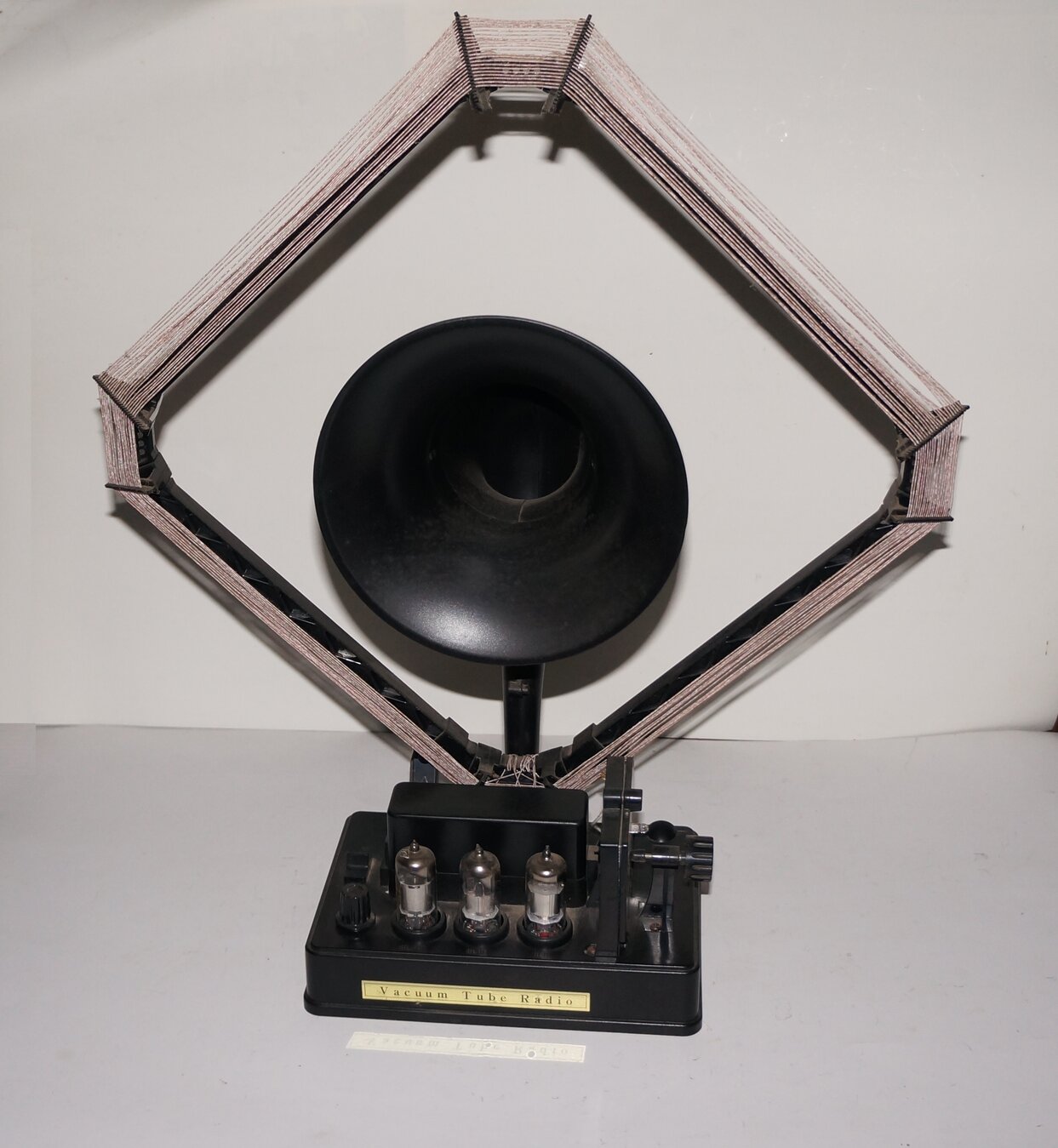
This was the first of my Gakken radio kits;
I purchased it in August 2006. It has been superseded with a "Version 2"
which includes a piezoelectric microphone for testing the audio stages,
and a larger output transformer. It was largely the 1920's look alike with
the frame aerial and horn speaker that attracted me to it.
This kit has been around longer than the
variometer tuned set so there's a bit more on the internet about it. Again,
it was only really intended for the Japanese market but the pictorial quality
of the manual makes for an easy assembly even if you can't read the words.
One important point is the variable capacitor. Peel off the plastic film
from one of the plates only. The film remaining on the other plate functions
as dielectric. Since purchasing my kit, an English manual has appeared.
It can be found here.
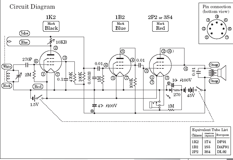
Gakken Vacuum Tube Radio kit is a standard regenerative design.
Regenerative Detector.
There is nothing unusual about the circuit,
except they aren't using the valves to full potential. The 1B2 and 2P2
are wired as triodes whereas more gain, and output could be had with them
in pentode configuration. The 1K2 functions as a pentode regenerative detector
with the usual grid leak components, 270pF and 2.2M in conjunction with
the diode formed by the grid and cathode (heater). Giving a slight positive
voltage to the grid improves sensitivity which is why the gird resistor
is returned to the positive heater terminal. Due to the use of a frame
aerial, the receiver is self contained needing no external aerial. It does
however mean there's a strong directional characteristic. An unusual feature
is the so called 'book capacitor'. It simply involves moving two hinged
plates closer or further apart to set the capacitance. The manual implies
this was a common feature in the 1920's. I've seen a lot of 1920's receivers
and not one yet has used this method of tuning.
Positive feedback is obtained with the
smaller winding in the plate circuit. The degree of feedback is controlled
by shunting a 10K pot across this winding, progressively loading it.
My main criticism is the regeneration
control. Forcibly lowering the Q of the tuned circuit by shunting
it with a rheostat to control oscillation is rather crude. The pot setting
is very critical and hard to optimally adjust. Backlash is also a problem.
Once it has started oscillating you have to turn the pot further back than
the point was where it starts to oscillate.
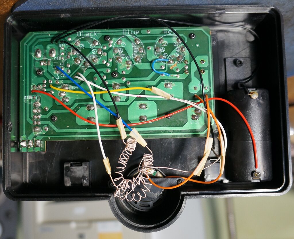
The PCB for Version 1 with wires connected. The instructions show
the aerial coil wires just twisted to the plastic wires from the PCB, but
I soldered mine. The C cell connections are visible to the right.
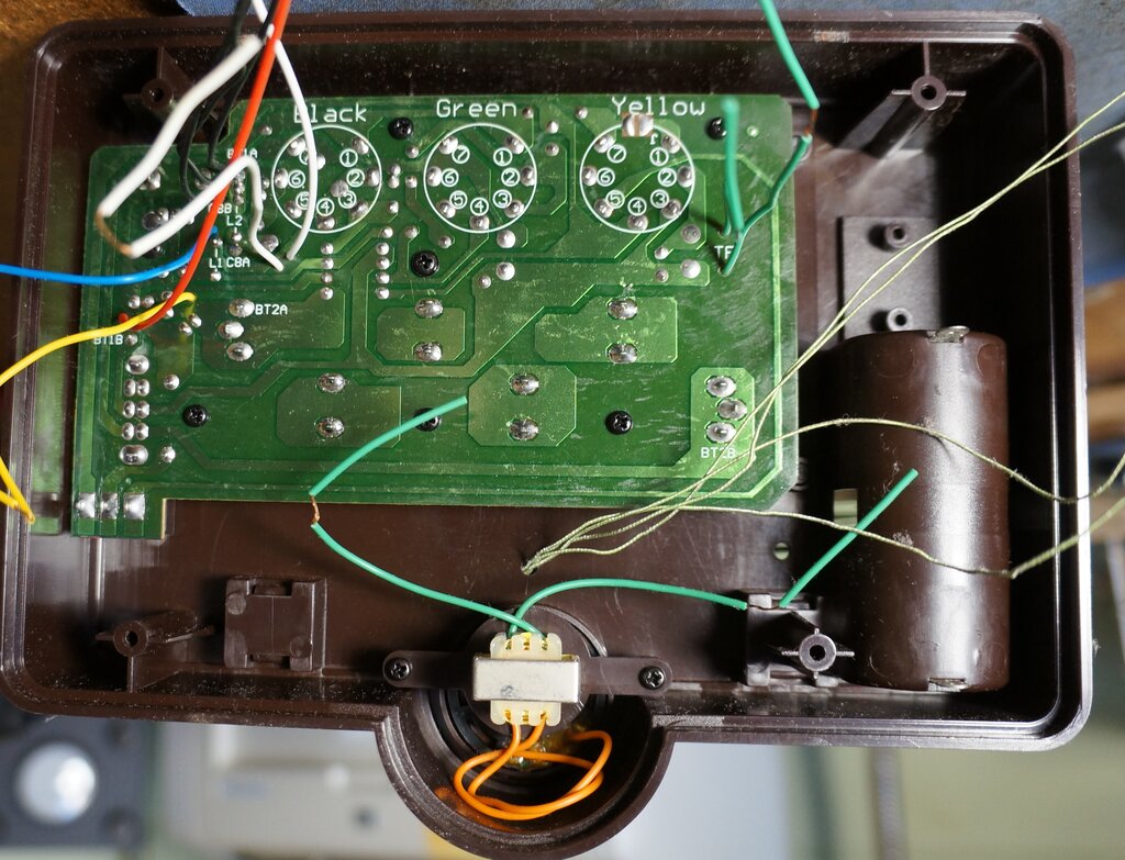
Version 2 PCB. This set has not been completed. Note that
pin 4 of the output valve (designated Yellow) is connected to the 45V supply
for pentode operation.
Audio stages.
Detected audio present at the plate then
proceeds to the next valve for further voltage amplification. This is a
pentode wired as a triode. Using it this way results in less gain so I
am curious as to why it has been designed this way. A much amplified audio
signal is available at the 1B2 plate for feeding the piezoelectric earphone,
or the output stage. Again, wiring the 2P2 as a triode reduces gain and
power output. The speaker transformer is much smaller than would normally
be used; it's about the size of something found in a small transistor radio.
As for the speaker itself, this is merely a driver from a set of Walkman
style headphones. Historically, that's not too far off the mark because
the horn speakers of the 1920's did in fact use an oversize headphone driver.
The led indicates power on due to the
HT current flow. The voltage drop across it and the 270R resistor also
creates the negative bias for the 2P2. An earphone is supplied with the
kit and can be plugged into the socket provided. Here, the earphone is
fed from the 1B2 and when its plug is inserted, the normally closed contacts
in the socket break the heater connection to the 2P2. This reduces the
current drawn from the C cell by 100mA. HT supply is five series connected
9V batteries giving 45V which is lower than the output valve is actually
rated for.
Performance.
In terms of RF sensitivity and selectivity,
it's like any other regenerative set. Interstate stations are easily received
at night. Apart from this, the radio has some serious limitations. These
could be fixed at the expense of losing originality. The worst aspect is
the tuning control. The 'book capacitor' suffers terribly from mechanical
instability. Not only does the adjustment screw thread have slop in it,
but just any pressure on the chassis distorts it, and the position of the
two 'plates'. It is rather difficult to tune weak stations because of this
and one has to gently prod the tuning control until the station comes into
tune. Next on the list is the regeneration control. As I expected it would,
it does suffer from backlash and critical adjustment. Also, the pot isn't
perfect and simply touching the knob without even turning it will alter
the resistance enough to throw it into oscillation. Thirdly, is the low
audio gain.
Three valves should drive the output into
overload, but with this set it's good enough for a quiet room but not much
more. I did rewire the output stage to a pentode which improved things
somewhat, but I think the audio voltage amplifier stage needs to be treated
likewise. The tiny speaker transformer and headphone driver look dubious
anyway. Nevertheless, I did try a full size speaker and transformer, and
while there was an improvement it wasn't startling. Incidentally, I found
troubles with with earphone socket and a dry joint - the radio would not
always produce sound.
How to improve it.
First thing would be replace the 'book
capacitor' with a proper tuning gang. Secondly, the regeneration control
needs to be improved. Maybe a high quality pot would reduce the critical
adjustment, but it wouldn't fix the backlash. The best way would be to
control the screen voltage of the 1K2. The 10K pot would have to be replaced
with something like 100 - 500K, used as a voltage divider across the 45V
supply to feed the detector screen grid. Quite a few PCB tracks would
have to be cut and joined to accommodate the changes.
For the audio stages, higher output will
be obtained if the output valve is wired as a pentode. As it happens, the
Version 2 circuit has made this improvement.
A larger speaker transformer should be
used, but to find one with a 10K primary that fits under the chassis is
the awkward part here. And finally, to the headphone driver, a proper miniature
speaker may provide an improvement. Jacking up the HT would help too, but
the problem is where to fit the extra 9V batteries.
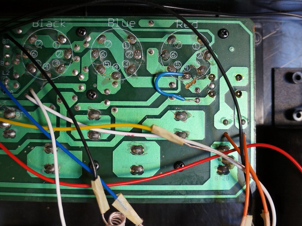
Pentode connection for the output valve. Note track cut at pin 4
and short blue wire added.
To connect the output valve as a pentode
(Version 1), cut the track to pin 4, and then connect pin 4 to the 45V
supply. Note the short blue wire in the photo above.
A further increase of gain would be obtained
by connecting the 1B2 as a pentode. I have not yet tried this, but if you
wish to experiment, cut the track between pin 4 and 5 so that pin 4 is
completely isolated. Next, connect a 0.1uF capacitor from pin 4 to earth
(you can use pin 7 for this). Finally, connect a resistor of 1M between
pin 4 and the 45V supply. This resistor might not be an optimum value,
so there is room for experimentation. I would expect best results to be
somewhere between 390k and 2.2M.