This three valve set requires no user regeneration adjustment.
This three valve set requires no user regeneration adjustment.
Introduction.
This set was a project described in Radio
& Hobbies in Australia, for December 1950. The title "Xmas Box Mantel"
reflects that such a set would make an ideal end of year project in time
for Christmas. Around this time, Radio and Hobbies presented a few simple
mantel sets, based around three valves. The idea was to present some designs
which were compact, and inexpensive, but practical for anyone to use.
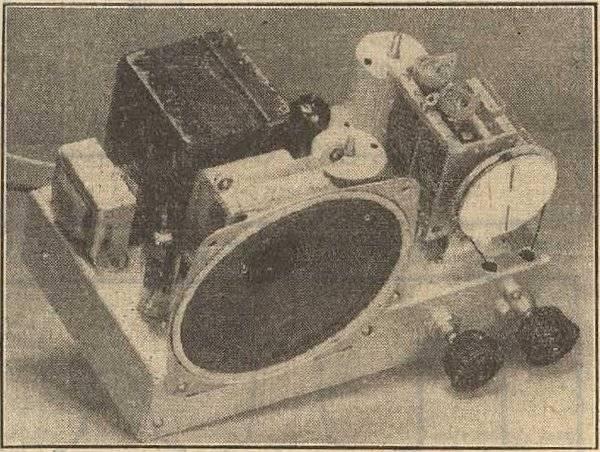
The original set as described by Radio & Hobbies.
The sets were TRF and/or regenerative designs. It is clear that R&H were responding to the fashion of midget sets, so popular in the U.S., but quite rare in Australia. Firstly, Australian components were just too large to make anything as compact. The multi section valves required to save space were not made in Australia, and the necessity for a power transformer also required a larger cabinet size. (Line cord resistors were not approved, and live chassis sets were seen as a shock hazard). Nevertheless, one prominent manufacturer did make a locally adapted midget set. Astor created a number of models based on the U.S. Emerson CF255. The 32L7 and 12B8 valves were imported and a conventional transformer power supply was used.
The Circuit.
Turning now to the circuit, it can be
seen that the 6N8 is a RF amplifier and detector, and the 6M5 is the audio
output.
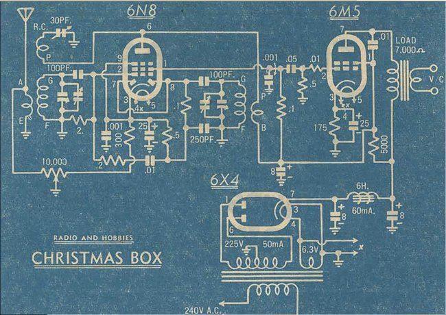
Circuit of the original set. The tuned circuits used commercially
made Reinartz and RF coils.
Starting at the aerial, the RF is fed into a conventional tuned circuit utilising one section of a dual gang condenser for tuning. The signal feeds into the 6N8 grid via a 100pF condenser. In the plate circuit is an RF transformer, tuned by the second condenser gang. The signal from this feeds a shunt diode detector, using the diodes inside the 6N8. Detected and filtered audio is now present across the 250pF. So far, this is like any conventional TRF set.
Reflex amplifier.
However, the 6N8 is reflexed. That is,
it performs not only as an RF amplifier, but also an AF amplifier. The
demodulated audio from the detector diodes is now fed back into the grid
of the 6N8. It feeds in via a .2M resistor so as to prevent the 250pF shunting
the RF signal to earth. The 2M completes the grid circuit to earth.
At this point, the 6N8 is amplifying the
incoming RF as well as the detected AF. This is quite possible without
any interference because the frequencies are so far apart. The RF transformer
does not respond to audio frequencies.
With a reflex amplifier, the logical point
to extract the audio signal is from the plate circuit, and indeed this
is often done. However, this requires a plate resistor across which to
develop the audio. The problem is that such a resistor requires a large
voltage drop across it to provide worthwhile audio gain. This in turns
reduces the plate voltage, and the efficiency of the valve as an RF amplifier.
A clever alternative is to extract the
audio from the screen grid instead. As screen current is lower than that
of the plate, a high value resistor can be used without any detriment.
Here, the screen grid functions as the plate of a triode. The audio load/screen
grid resistor here is .1M, or 100K. Screen bypassing is performed by a
.001uF. This value is sufficient for bypassing the RF, but not the AF.
The audio now feeds into the output stage.
This uses a 6M5 output pentode in a completely conventional cathode biased
circuit.
Regeneration.
The RF amplifier has regeneration applied
which increases gain and selectivity. A preset amount of positive feedback
is provided by the third winding on the aerial coil, which is controlled
by the preset 30pF trimmer. Unfortunately, the idea of preset regeneration
has limitations. It can be imagined that as frequency increases, the reactance
of the 30pF trimmer condenser decreases, causing more RF current to flow
in the feedback winding. Indeed this does happen, resulting in more regeneration
and higher gain at the top end of the band. Also, different aerials will
load the first tuned circuit to a lesser or greater degree, thus affecting
the amount of regeneration. For this reason, the trimmer is best adjusted
on the aerial the set is used with. The lesser amount of gain at the low
frequency end of the band is less obvious in this receiver than it would
be in a single stage regenerative receiver, because of the additional gain
provided by the RF stage. It should also be mentioned that this set was
designed for local station listening, but the point was made that the preset
regeneration control could be replaced with a user adjustable panel mount
type for optimum user adjustment, if the ultimate sensitivity was required.
In practice, the preset control is adjusted with the set tuned to the top
end of the band, to just before the point of oscillation. The volume control
must be full on so that the RF amplifier is operating at full gain. Adjusted
this way, the set will never break into oscillation with any setting of
the tuning or volume controls.
Volume Control.
Volume control is achieved with a 10K
pot using a circuit that was very common before receivers incorporated
AVC. As the 6N8 is a remote cut off pentode, gain control can be reduced
by increasing the grid bias. Here, the 10K pot is in the cathode circuit,
so as resistance is increased, so does the cathode voltage relative to
the control grid. However, even at maximum resistance, it's possible that
in strong signal areas some signal will still pass through, making it impossible
to reduce the volume sufficiently. This is dealt with by using the other
end of the 10K pot to shunt the aerial signal to earth. In the minimum
volume position, the 6N8 is operating with maximum bias but the aerial
is also shorted out.
The Valves.
One of the successes of this circuit is
to do with the 6N8 and 6M5 valves. These belonged to the first generation
of 9 pin valves which had recently been released by Philips in Australia.
In the series was the 6V4/EZ80 rectifier, 6M5/EL80 output pentode, 6N8/EBF80
remote cut off pentode/dual diode, 6BH5/EF85 remote cut off pentode, 6BD7/EBC80
triode/dual diode, and 6AN7/ECH80 triode hexode converter.
Strangely, U.S. designs continued on with
their comparatively low gain valves right until the end of the valve era.
European valve design had always had a tradition of high gain and efficiency
(the pentode, or "penthode" being a Philips invention), and Australian
receivers were able to take advantage of this. For example, the 6N8 has
twice the gain of the similarly used 6G8, and the 6M5 has over twice the
gain of the popular American 6V6 or 6AQ5.
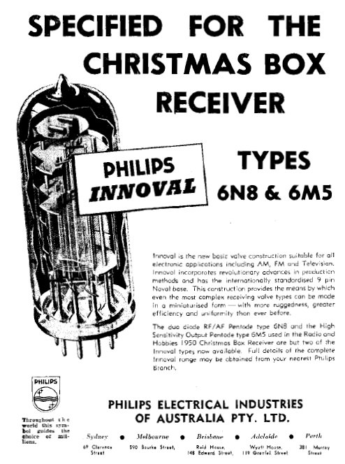
This Philips ad from December 1950 mentions the R&H project
of the same month.
The 6M5 was an extremely popular valve in Australia, but despite this it is virtually unknown in other parts of the world. Electrically, it is the same as the common European type EL41, except that the EL41 has an 8 pin Rimlock base. Both the 6M5 and EL41 are the miniature version of the octal EL3NG and EL33. On the subject of reliability, I have never seen a faulty 6M5. However, early versions sometimes did suffer from silver migration between the screen and control grid pins, which happen to be adjacent to each other. The pins were silver plated. If you work on a circuit where the 6M5 appears to suffer grid emission, scrape and clean the area between pins 1 and 2 before assuming the valve is faulty.
Constructing the set.
This was one of these projects that had
been on the "to build" list for years. At the end of 2012, I finally got
around to it. Somewhat coincidentally, but not intended, it was right on
Christmas when I built it. With the components to hand, I did some slight
modifications, but the set is largely as presented by R&H.
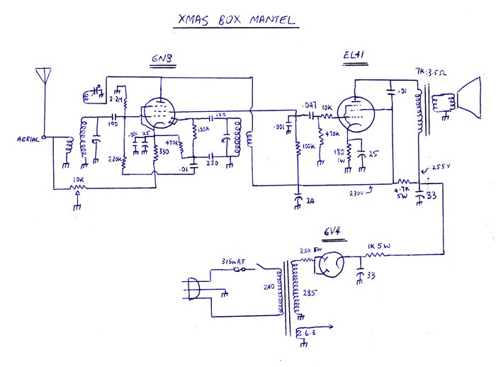
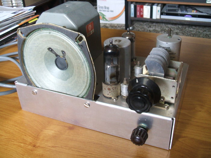
Circuit for my version of the set, built in December 2012.
Apart from the use of preferred value resistors
and condensers, the receiver circuit is the same. As I happened to have
an 8 pin Rimlock socket and a number of EL41's, I decided to make use of
one, rather than the 6M5. As the two are electrically equivalent, no circuit
changes were required.
The main difference is the power supply.
Here, I used what was to hand, and the transformer I decided on had only
one 285V secondary winding for the B supply. This meant that half wave
rectification would have to be used if I wanted to keep with a valve rectifier.
With high value electrolytics filtering is not a problem and no hum is
evident. I used a 6V4 instead of a 6X4 simply because it was what was nearest
in the valve box at the time. The plates are connected together for half
wave operation, and to make things easier on the valve, a 250R resistor
limits the peak current. Instead of using a choke for filtering, I used
a resistor. RC filtering is perfectly acceptable with modern high value
capacitors.
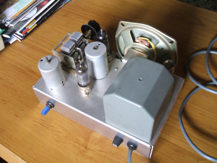
Reinartz coil in bottom left corner. 6N8 at rear, EL41 at front,
and 6V4 at top right in front of the transformer.
The Reinartz and RF transformer coils were
commercially made by Aegis, but there is no reason not to use homemade
types. The speaker transformer was acquired from an Astor radiogram chassis
many years ago. Its 3.5R secondary is a good match to the 4R speaker I
used. The power transformer is an AWA type, commonly used in professional
and industrial equipment. Being moulded in grey epoxy it is impossible
to know its ratings, but one could assume from the size that they would
be sufficient for a simple receiver like this.
A 315mA time delay fuse protects the transformer.
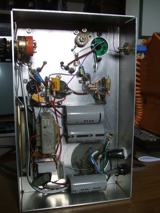
Under the chassis reveals a very uncluttered layout.
Performance.
The set performs very well. As expected,
the gain picks up towards the high frequency end of the band. In my location,
all Sydney transmitters are received very well over the 80km distance.
2BS from Bathurst is receivable during the day. Towards the end of the
afternoon, interstate stations begin to make their appearance.
As a rough comparison, this set has sensitivity
similar to that of a one stage TRF receiver. Sound quality is good, with
the diode detector providing higher fidelity on stronger signals than is
possible with a grid leak detector. The volume control range is more adequate
than it needs to be, with most of the control being concentrated at one
end of the pot travel. However, it has to be pointed out the signals in
my area are weaker than what the set was intended for. A 5K pot would give
a smoother action in this instance.
It would be better from a design point
of view to have the regeneration applied to the detector coil instead of
the aerial coil. This would eliminate the loading effect of different aerials
affecting the regeneration. Indeed, the Emerson CF-255 and similar Astor
designs do this.
There is no doubt that for an economical
simplified receiver usable by anyone, the design is a very satisfactory
one.