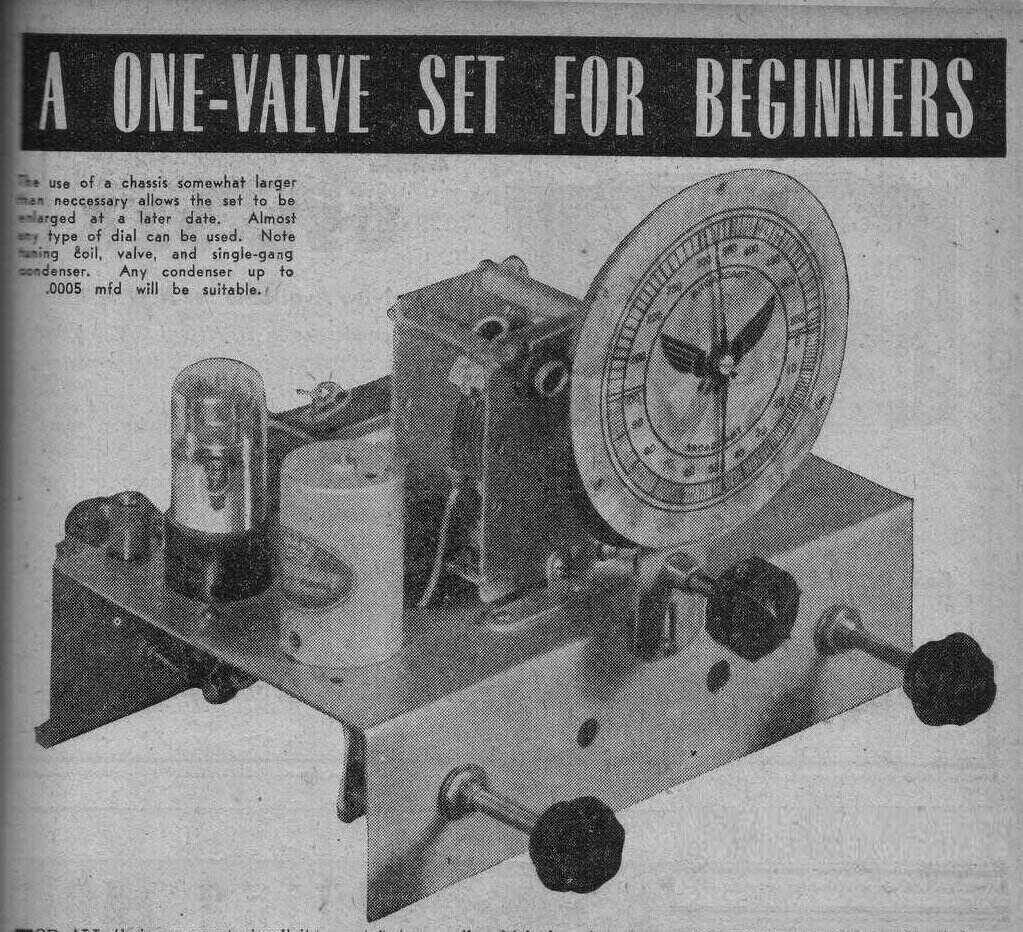
Low voltage B+ receiver and amplifier circuits using mains type valves have been described elsewhere on the site. This article looks at the use of low B+ with battery type valves, used in one valve receiver circuits.
One valve regenerative receivers using a 1Q5 were a popular project, because good results could be obtained with only 9V B+. Not only did this make for a more compact set, but one that was considerably cheaper to operate than one requiring a 45V battery. Such sets were popular with campers and hikers.
Hiker's One.
In fact, the whole background of the design
comes from a circuit, known in this part of the world as the "Hiker's One".
The circuit was first presented in QST for October 1935 and was a shortwave
receiver. It was a two valve receiver with a 49 operating as a regenerative
detector in space charge mode, and a 30 operating as an audio amplifier
in the normal way. The circuit was popularised by an article in Popular
Mechanics for September 1936, which was for a medium wave receiver, using
only a single 49.
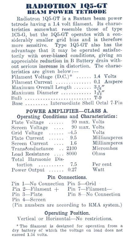
Release notes from AWV, July 1939. At right is the equivalent Philips
DL36.
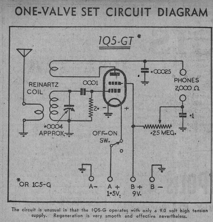
Since the 1Q5 is designed for a relatively high cathode current (11.1mA) at 90V, it could be imagined that when used as a regenerative detector, only requiring a fraction of a milliamp, that operation at lower voltage should be possible. Indeed, good performance was obtained with only 9V, and the Hiker's circuit lived on with its economical B+ supply. Type 1C5 is similar, though less sensitive, and was also recommended for the circuit.
Other 9V HT Receivers.
"Radio & Hobbies in Australia" presented
a 1Q5 receiver design in July 1946. It was shown using a size D cell for
the filament, and a multi-tapped 9V C battery for the B+.
From Radio & Hobbies, July 1946. Coil data is given at right.
Coil former is 1.25"
Both Radio & Hobbies and the Lamphouse also presented two valve versions of their 9V sets, using another 1Q5, 1C5, or 49 as an audio amplifier.
Once miniature output valves became available, there was no reason not to use them. The following circuit uses a 1S4.
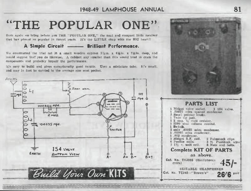
From the Lamphouse 1948-1949, this circuit uses a 1S4. One wonders
if performance might be improved by connecting the 1S4 as a pentode, rather
than as a triode.
Radio & Hobbies used the 3S4 in a circuit with a variable capacitor for regeneration control.
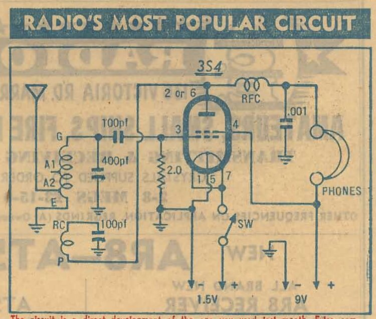
From Radio & Hobbies, December 1952, this set was part of an
instructional series, starting from a crystal set and ending up as a three
valve portable.
Although it wasn't exactly 9V, the final low voltage B+ one valve circuit presented by Radio & Hobbies was in September 1954.
From Radio & Hobbies, September 1954, this set used a 30 triode
with 13.5V B+ obtained from three 4.5V cycle lamp batteries.
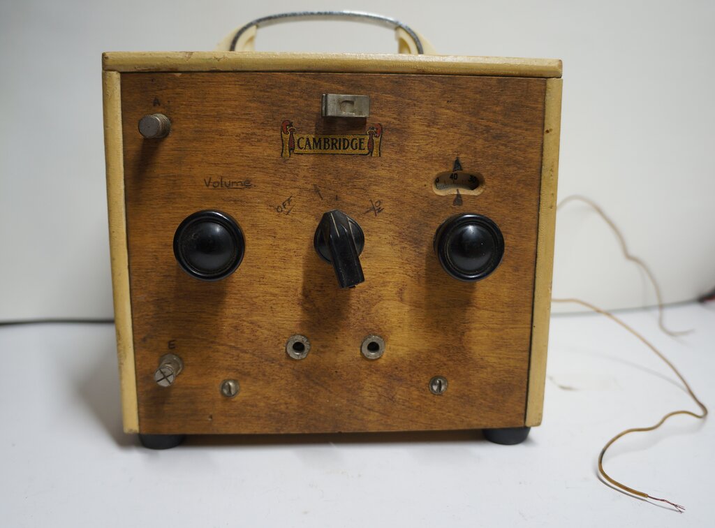
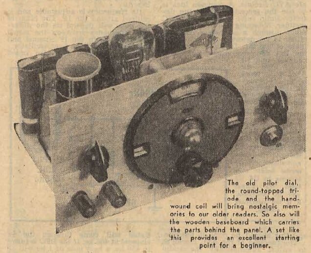
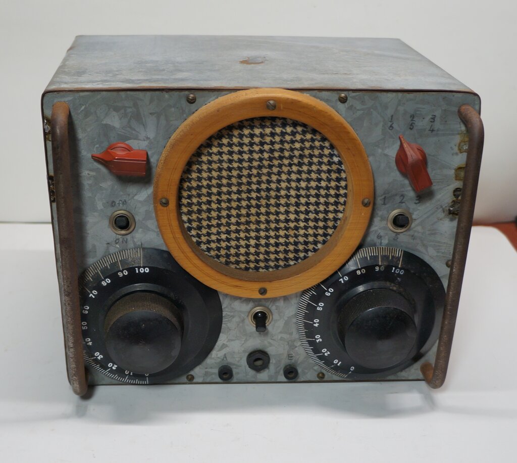
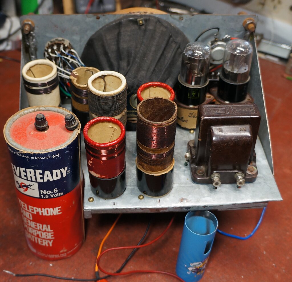
1. The Cabinet Set.
Pictured at the beginning of this article,
this set was completely enclosed in a wooden cabinet, fitted with a handle.
The cabinet has been made from the wood of a butter box, the origin of
which seems to be from the town of Lyttelton, in NZ's South Island, from
the printing on the inside.
Inside the cabinet version.
The tuning capacitor is a rather ancient Stewart Warner, complete with 0-100 dial. It was once fitted with a reduction drive, but the drive gear has been removed. The tuning knob attaches directly to the shaft. The other controls are a rotary on/off switch, and the regeneration control potentiometer. A primitive battery holder for two D cells had been made up on the back of the chassis. Battery holders, as we know them today, were virtually non existent as an individual component available for purchase. There is space at the side of the chassis for the 9V battery. An English made Philips DL36 had been fitted.
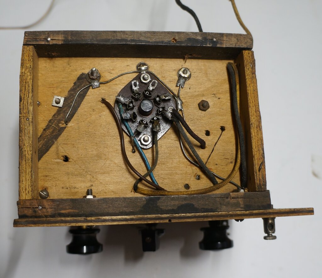
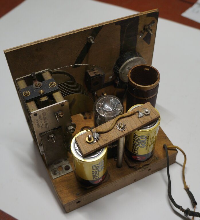
Under the chassis. For a simple MW set like this, a wooden chassis
is acceptable.
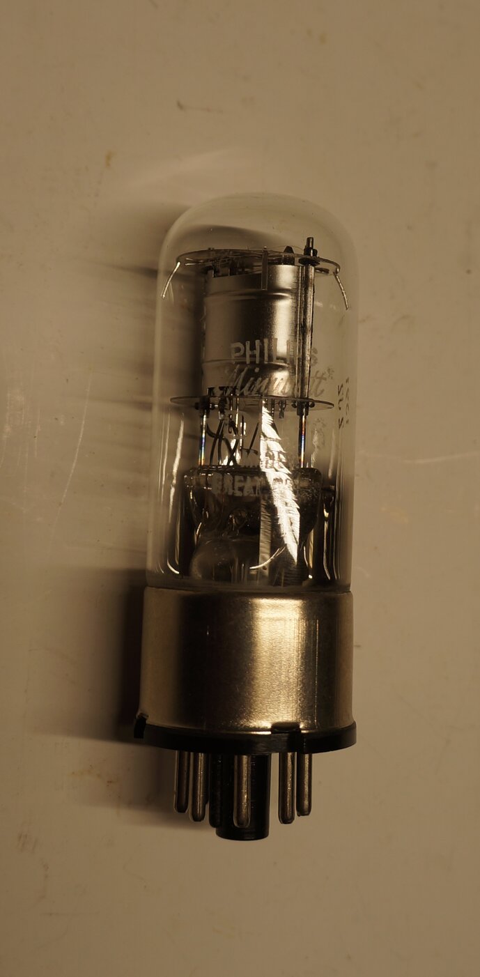
The DL36 had suffered a common fault with
the style of valve construction used. Some octal valves did not have a
full bakelite base, but had just the pins in a bakelite moulding. The glass
was secured to this via a metal ring (see pic above of the DL36). The metal
ring often splits, which is what had happened here. The valve was flopping
about on its wires, which fortunately had not broken off. It was an easy
repair, just a length of tape around the ring holding it all back together.
And I'm pleased to say the valve itself was undamaged.
Since the valve socket is below the chassis,
and with the thickness of the wood, the valve cannot be fully seated. In
fact, the valve was just about to fall out when I got the set.
A nice thing about sets like this is they'll
usually work straight away. With only 9V, one does not have to worry about
replacing leaky paper condensers (not that there are any). With only one
resistor, whose value is not critical, this doesn't even need checking.
And so it was, with two D cells put in
the holder, and 9V from a bench supply, the set worked straight away.
In fact, I'd forgotten just how well this
design works. It was late afternoon, and the distant stations were starting
to come in at good strength. After sunset, my 'sensitivity test station';
Newstalk ZB from Wellington was coming in (2ZB 1035kHz 50kW). Distance
is about 2200km. The regeneration control worked as smoothly as one could
wish, and even with no vernier control, there was no difficulty tuning
between stations.
One odd thing I'd noticed was that the 9V supply wires had been extended through holes in the cabinet. It is curious why this was done, since there's plenty of room inside the cabinet for a battery. In the modern day, a 216 type 9V battery is a logical choice, although a set of six AA cells is more keeping in with the period theme. Also appropriate would be two 4.5V cycle lamp batteries, but these are now difficult to obtain.
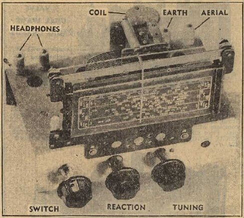
Headphone terminals are on the front panel.
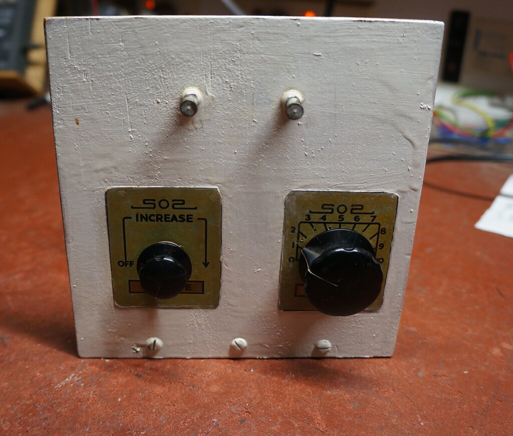
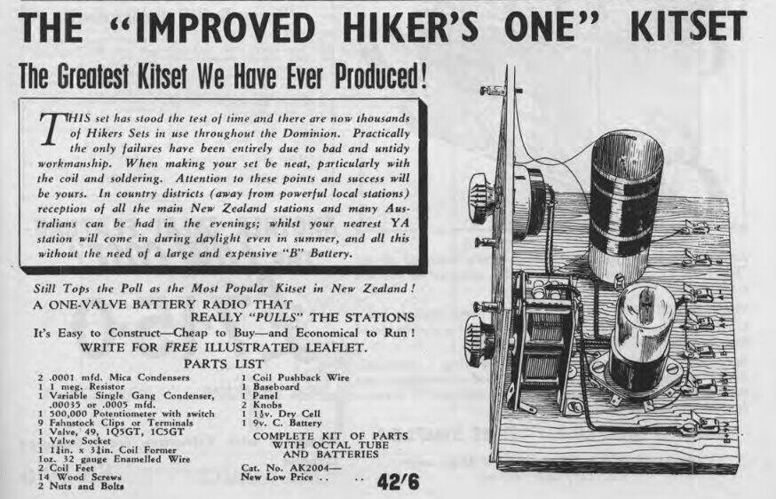
The second set looked suspiciously like
a Lamphouse kit, although a closer look shows that it is not. The parts
layout is much the same, as is the row of Fahenstock terminals along the
back of the chassis. However, there are fewer terminals, and the circuit
is slightly different. The function of each terminal has been stamped into
the wood which definitely supports the 'it was a kit' theory.
The control label logos suggest S.O.S.
Radio, another kitset supplier.
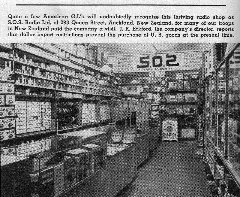
S.O.S. Radio mentioned in "Radio & Television News", March 1951.
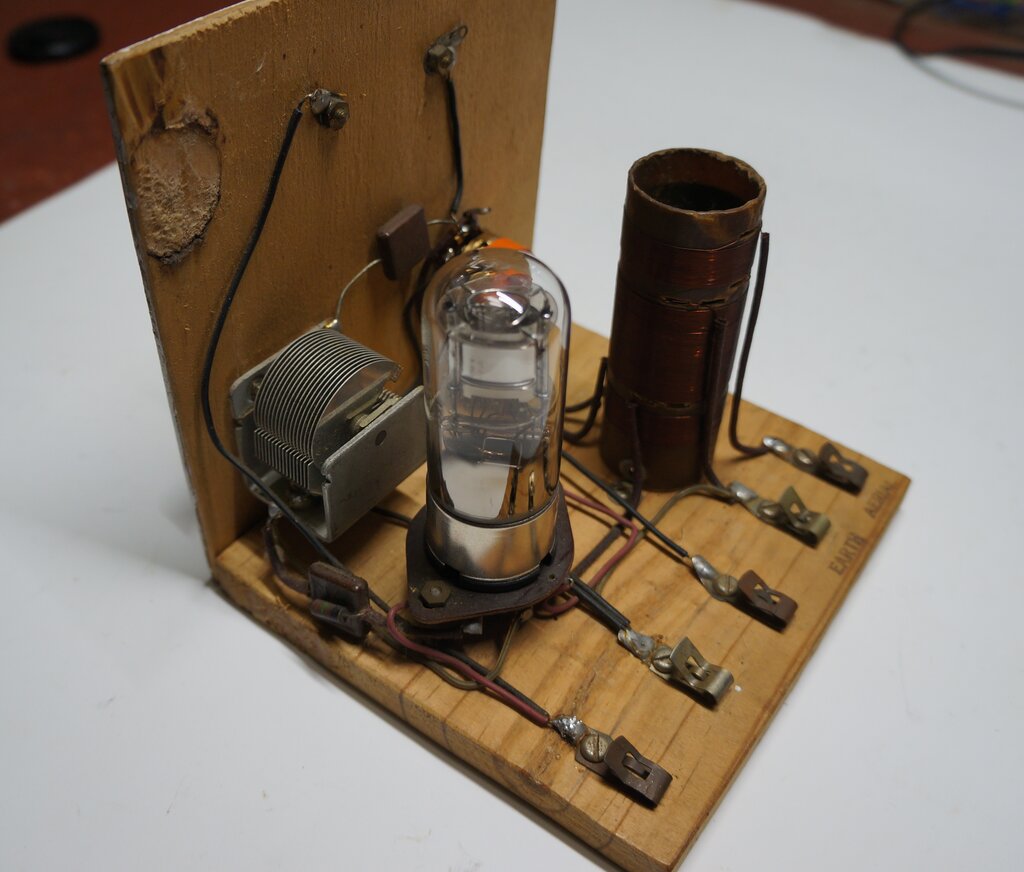
In this set, the variable condenser is an English "Polar" type. Instead of the separate switch and pot, a combined switch pot is used. The components are more modern, being from the early 1950's, with PVC wire, a more modern grid resistor, and mica capacitors. The valve fitted is another English made Philips DL36. Two of the Fahenstock terminals had broken, but luckily I had replacements.
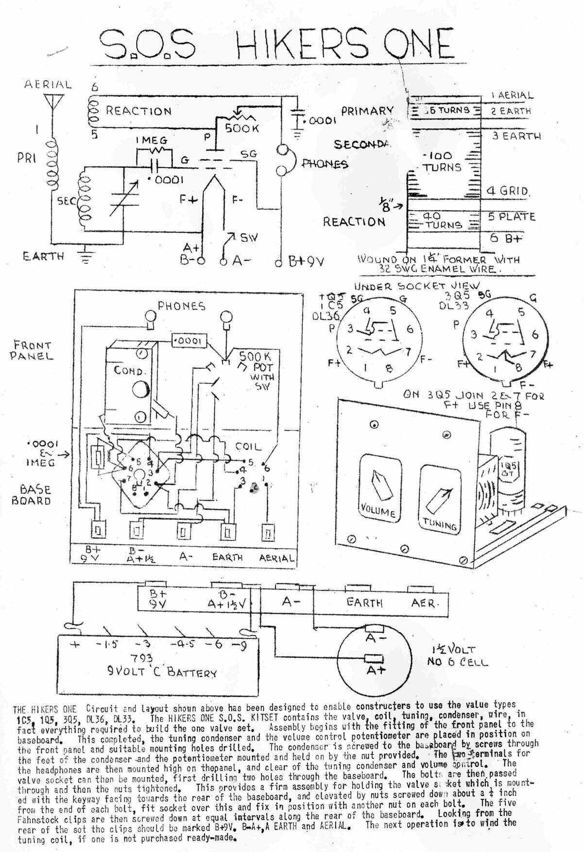
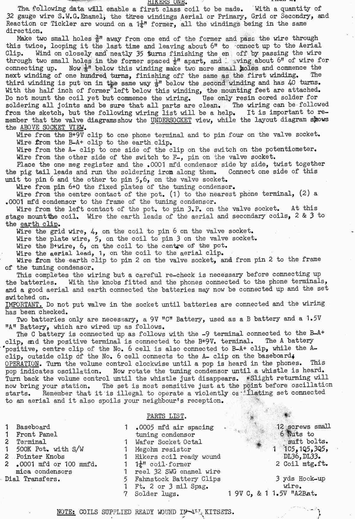
Update March 2026: Lance was able to locate the instructions for the S.O.S. receiver. They were in poor, though readable, condition. With his Photoshop skills, they were tidied up nicely to present here:
When it came to testing this set, results
were very different. It was not possible to reduce the regeneration sufficiently
unless the B+ was reduced to 8V.
At this point, I hadn't actually traced
out the circuit, and had just assumed it was the same as the Radio &
Hobbies design, since the pot was clearly marked 500k, which would imply
screen grid control. At a glance, both sets appeared to be using
the same circuit, so why the difference?
From the 1950-51 Lamphouse catalog. Looks the same doesn't it? A
closer looks reveals subtle differences.
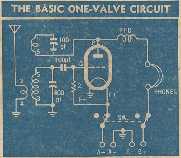
The open chassis set's physical appearance mimics the Lamphouse design, but on closer looking at the actual Lamphouse circuit, the 1Q5 operates in space charge mode, with +1.5V on grid 1, and the signal fed into grid 2. However, both sets I have use the conventional tetrode connections, with the signal fed into grid 1 and the 9V supply fed to grid 2.
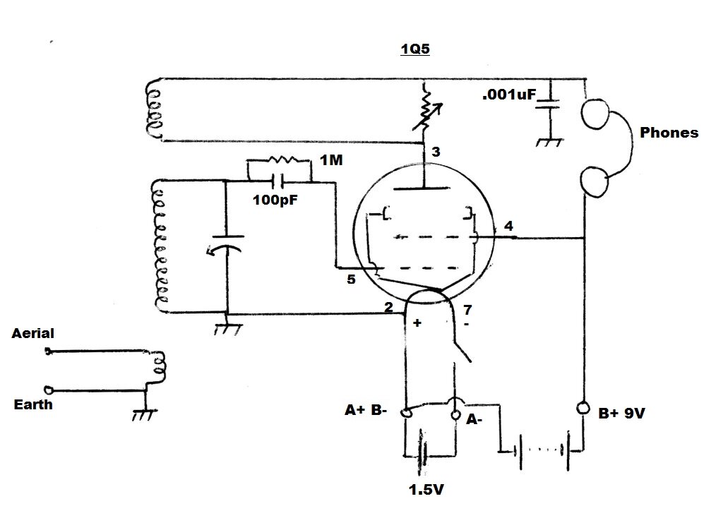
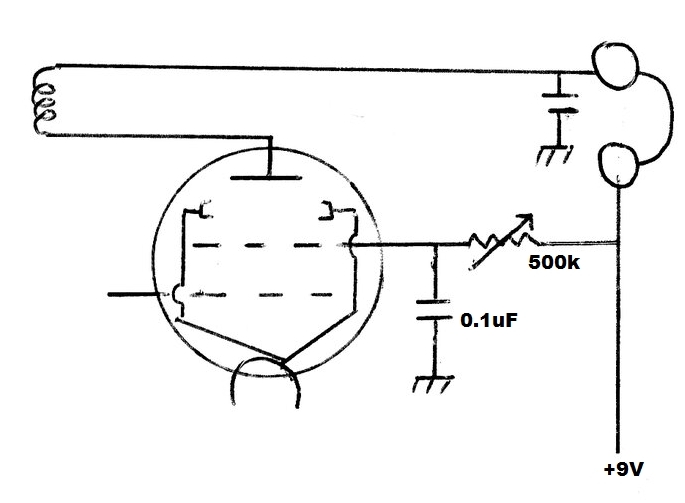
Circuit of both sets. The regeneration pot value is 10k for the
cabinet set, and was 500k for the open chassis set. It is now 2.5k.
Regeneration Control.
The set built in the cabinet worked perfectly
and did not need any work. The question was with the open chassis set;
what to do about the regeneration control. The pot in the cabinet set was
not labelled, so I measured it and found it to be 14.6k. It would appear
it was a 10k type which had drifted. 5k to 50k is typical of the value
used for shunt control, so all was good here. No wonder control was poor
with the open chassis set, with its 500k pot. As it was, the control action
was cramped at one end, with most of the pot travel doing nothing. A further
complication arises with switch pots, in that the lowest minimum resistance
is higher than a normal pot, unless the carbon track has been specifically
designed for such use. The reason for this is because of the wiper travel
before the switch actually turns on. Incidentally, switch pots tend to
wear out faster, since every time the set is switched on or off, the wiper
moves over the carbon track. With a separate switch, the potentiometer
will usually be left in much the same position.
Using the 500k Pot.
With 9V B+, the minimum resistance of
the pot was too high. Seeing as the pot was 500k, it seemed logical to
convert the circuit to the R&H design. I must admit an element of surprise
when I had a closer look at their circuit. In previous times when I had
glanced upon this circuit, I just thought the 250k pot was in series with
the screen grid. But looking closer, we see the screen is fixed at 9V,
and the pot varies the plate voltage instead. It's an unusual way to do
things. R&H's theory was that fixing the screen at 9V would ensure
the greatest electron flow for the low plate voltage. I tried it, and it
certainly gave very smooth control, but soon became aware of a serious
problem. Below a certain plate voltage, the signal suddenly dropped off
in volume and became very distorted.
If the optimum regeneration setting was
above this point, all was good and it worked well. But, if it was necessary
to go below this point to get it to stop oscillating, it was unsatisfactory.
One possibility is the aerial connected to the R&H lab was of sufficient
length to load down the tuned circuit, so that their set was always operated
above this point. Also there is a slight difference in the R&H coil
specifications, compared to those in the receivers at hand. The R&H
set used a commercially made Reinartz coil, but details were provided for
those who wanted to wind their own.
Why did my own construction of the set
ca. 2000 not have this problem? I'm very certain I had wired the set for
screen grid control. And so, this is what I tried next. The 500k pot was
connected in series with the screen and bypassed with a 0.1uF condenser.
This worked very well with a perfectly smooth control.
There is one possible disadvantage with
screen grid control. That is, since the gain of the valve is affected by
the screen grid voltage, the gain will always have to be lower than what
it could be, in order to back off the regeneration to the point just below
oscillation. This is not problematic with circuits operating with conventional
B+ of greater than 45V, since the gain is already more than enough. But
with only 9V, when we're trying to get every bit out of the valve, it could
be. Fortunately, this did not turn out to be so, since the optimum screen
voltage was around 7.5V, and gain was still ample.
Connecting the 500k pot as a rheostat in
series with the screen seemed like the answer. One characteristic of the
rheostat connection is that the volume cannot be reduced to nothing. With
the low volume level of a one valve set, this is not a problem, but I tried
using the pot as a voltage divider. This gave complete control as expected,
but would be unsuitable for this particular set, since there's only one
set of switch contacts. This means there's a 500k load across the 9V battery
even with the set switched off. Ether a rheostat connection has to be used,
or a double pole switch fitted.
The 500k pot works well as a screen grid control.
I was happy with the rheostat connection,
but before implementing it, I thought I'd have a look through my switch
pots and see what I had in the way of lower values, so as to retain shunt
control and keep the original wiring.
25k was tried and worked acceptably, although
the control was cramped at one end. I found a 2.5k pot which worked very
well. It seems the optimum shunt resistance is around 1k, so the 2.5k pot
is ideal. I installed it permanently.
In comparison to the screen grid control,
there's very little to choose between how the set performs. There was no
obvious change in sensitivity and volume.
The question remains as to why a 500k pot was originally used in this set as a shunt control. I can only put this down to the fact that the most easily available switch pot was the 500k type, since this is the standard value of volume control in valve circuits. The original Popular Mechanics circuit uses 500k, and this was duplicated in the Lamphouse version. 500k just doesn't seem right, since the regeneration coil is a low impedance circuit, and it's interesting to note the 10k pot in the cabinet version, and also the more recent HRSA circuit, as shown previously. Lower resistance volume controls did not become common until the transistor era. (5k and 10k volume controls were common in 1930's sets, but they didn't usually include a switch). The B+ terminal is clearly labelled as 9V, so it is a mystery how the constructor of this set was able to use it.
Headphones.
This kind of set was intended to be used
with high impedance headphones, of the type that go right back to the beginning
of radio. Typically, these have a resistance of 2000 ohms.
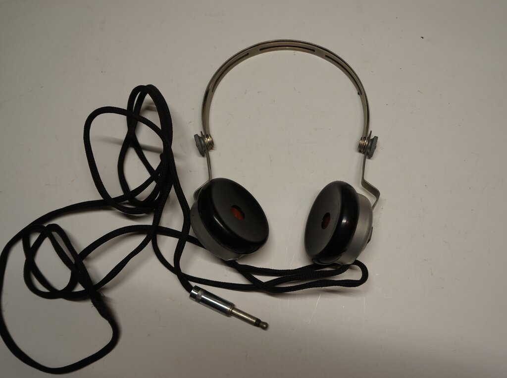
High impedance phones like this were used with crystal and one and
two valve sets.
Unfortunately, they are very uncomfortable with the hard bakelite earpieces, and the sound quality is rather poor. Much better results can be obtained with modern stereo headphones and a matching transformer.
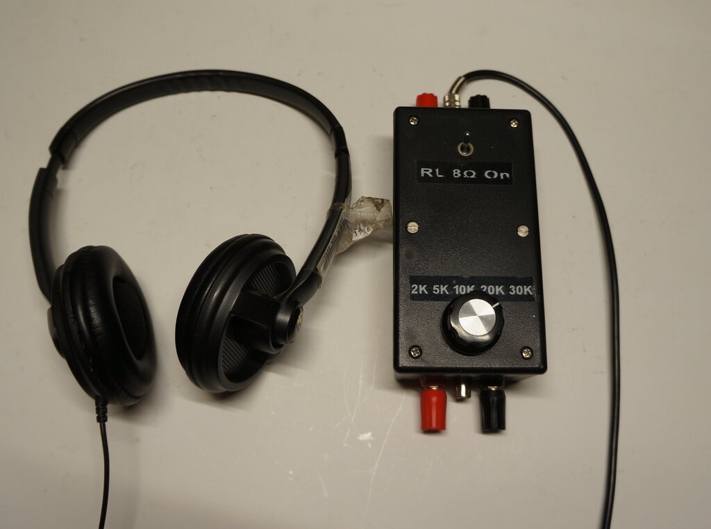
Modern headphones with transformer matching are a far superior substitute.
Although high impedance headphones are
usually quoted as being "2000 ohms", this is the DC resistance. The impedance
(AC resistance) is a lot higher, by approximately 10 times. So, to use
modern phones, the transformer needs to reflect an impedance of at least
20k. The best type of transformer to use is a multi-tapped 100V type used
for public address systems. The primary impedances are not usually quoted,
but the input power levels are. From that, the impedances can be calculated.
See here for further
details.
With the 1Q5 sets, the 30k tapping provided
the loudest volume, equal to the high impedance phones. The 20k tap was
almost as good, but the volume dropped off considerably with lower impedances.
B+ current is around 280uA, so even a small
9V type 216 battery is practical. Filament current is 100mA, which is probably
best obtained from an alkaline D cell. Since these have about 20Ah capacity,
about 200 hours operation should be possible. I am very wary of running
battery valve filaments off a bench power supply, since the possibility
of an accident is too great. Battery valves won't survive an overload,
no matter how momentary.
Testing circuits with battery valves needs
to be done with utmost care. There are many sad tales of a whole set of
valves blown when the B+ got mixed up with the filament circuit.
For this reason, during the testing of
these two sets, I used a bench power supply for the B+ only, with the current
limit set to only a few mA. This way, the 100mA filament of the 1Q5 could
not be damaged in error. It is worth noting also, that filament continuity
checks on battery valves using a multimeter can cause damage. If the multimeter
uses anything more than a 1.5V cell for its ohms range, it's possible for
high enough current, particularly on the low ohms range, to pass through
the filament and destroy it. Use a high ohms range if testing filaments.
One other aspect to be aware of, for those
not familiar with battery valves, is that the glowing filaments are barely
visible, if at all. Do not expect them to light up in the same way as mains
type valves do.
The parts to build this set are all standard, although of course the tuning condenser will be the most difficult to get, if buying new. Nevertheless, they are available from a few suppliers, such as Antique Electronic Supply.
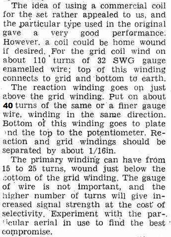
According to the Lamphouse specifications, the coil is wound with 32 gauge enamelled copper wire on a 1.5" diameter former. In the modern day, PVC pipe or conduit makes a good former. Regeneration is 40 turns, grid 100 turns, aerial 35 turns. Spacing between each winding is 1/16". Windings phased as per the circuit diagram. There is a slight difference in coil spacings with the two sets described, but it is not super critical. The less spacing, the tighter the coupling, and vice versa. There is some room for experiment here.
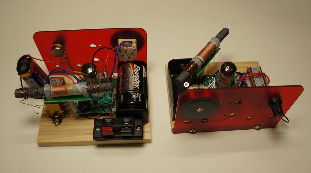
Chinese Hiker's One kits. Modified version on left.
For sale via the usual sources of such things, eBay and AliExpress, are various kit radios from China using valves. Among them are several variations of the Hiker's One design using a 2P2 battery valve. Other sets have two or three valves, with some covering the SW bands. There is also a super-regenerative kit for VHF using one or two valves.
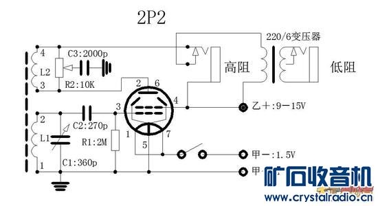
Circuit of the 2P2 receiver. There are some minor variations between
circuits.
A ferrite loopstick is supplied with these
kits instead of an older style air cored coil. These are still being made,
and thus easier to supply. It's possible to use the radio in a strong signal
area without an external aerial.
The 2P2 is equivalent to a 3S4, which
being a battery output valve, should work in the same manner as a 1Q5.
As with the original 1Q5 circuit, only 9V B+ is required.
Schematically, the only difference with the 2P2 circuit is the regeneration control. Instead of a variable shunt across the regeneration winding, the potentiometer varies the amount of bypassing to earth. Consider the pot wiper to be in the upper most position. The full 10k resistance is across the winding, and the wiper connects the 2000pF bypass to the output transformer plate connection. Thus, regeneration takes place, since the full winding is in circuit. Now, consider when the pot wiper is at the lowest setting. The 2000pF bypasses the 2P2 plate to earth, so that none of the RF on the plate reaches the winding. There is then no regeneration.
There are some slight variations with the
actual circuit. The particular examples I have don't include the high impedance
headphone socket. The grid capacitor is 240pF, and the tuning capacitor
measured 278pF. C3 is 2200pF. These are not critical values.
Also, there is some difference with the
battery connections. The 1.5V positive connects to pins 1 and 7, and the
negative connects to earth via the switch. The 9V negative returns to the
1.5V positive, thus giving 10.5V for the B+.
Construction of the set is on a pine board
with a plastic panel; the latter designed to be used with several other
types of kit. A commercially made PCB and ceramic valve socket gives a
professional look to the electronic part of the set. The output transformer
is a small 220 to 6V type. Turns ratio is 36.7. If the headphones are 8R
(two 16R in parallel), the reflected impedance is close to 11k. The headphone
socket is a stereo 3.5mm type with both channels in parallel.
I initially wasn't too keen on the tuning
capacitor mounted on the plastic panel, since there would be nothing to
shield it from hand capacitance. Ideally the front panel would be metal
of some sort, and earthed. Also, the wires to the regeneration pot were
longer than I'd like (I'm too used to VHF!) and I wondered how stable the
set would be in operation.
The first power up was disappointing. The two 50kW ABC stations were barely audible, and required critical adjustment. Connecting the outdoor aerial was necessary, and to start with I did that by connecting to the active end of the aerial coil by about 10pF of capacitance. This brought up the volume, but the set was difficult to tune, with the hand capacitance evident. It was impossible to tune above about 800kHz, but instead was able to tune to one of the airport beacons on 347kHz. Something was not right with the tuned circuit. Either the capacitance or inductance was too high.
First thing was to check the tuning condenser.
I discovered the wires were reversed for the fixed and moving plates, which
would have made the hand capacitance effect worse. I noted the trimmer
capacitor adjustment had no effect.
The particular tuning capacitor supplied
appears to be for a MW/SW and VHF type of set. There are two sections of
6-278pF and another two of 6-17pF. Not surprisingly for this set, only
one of the 278pF sections is used. I noted that the trimmer capacitors
had separate terminals which is why they had no effect. But why could it
not tune up to the high frequency end of broadcast band? That leaves the
aerial coil, and this was where the surprise was lurking.
Unsuitable Aerial Coil.
I was rather surprised to find the aerial
coil measured 906uH. For a MW set, it should be a fraction of that; somewhere
around 200uH. Maybe it was something to do with the ferrite rod itself.
I tried another rod in the coil and the result was much the same.
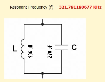
Calculating the resonant frequency, it was obvious what the problem was. With a 270pF capacitor and a 906uH coil, the frequency is 322kHz. No wonder it received the LW airport beacons and not the upper end of the broadcast band. A further calculation revealed the coil needed to be reduced to about 330uH, for 530kHz to be the lowest frequency. The only thing to do now was start removing turns. With 47 turns removed, the inductance was now 343uH. The set now tuned the complete broadcast band. The final thing was a proper external aerial connection. I simply wound 13 turns on the other end of the ferrite rod and added a set of terminals. A separate primary coil is preferable to a capacitive coupling, since the loading of the aerial has less effect, and the gain is more consistent across the band. In the introductory photo, you can see the lesser amount of coil turns on the modified receiver, and the new primary coil, and terminals. I would have liked to use Fahnestock clips for the terminals, but unless you live inside the U.S. they cost a small fortune. I used spring speaker terminals instead.
With that done, the receiver was working
very well. The regeneration control is very smooth with no backlash. Overall
performance is much the same as the 1Q5 receivers. Hand capacitance is
not a problem, and even distant stations can be easily tuned, without it
going off frequency when the hand is removed from the tuning knob. The
PCB has 9-18V printed on the B+ terminal. I found no difference between
9 and 18V, except the regeneration point is slightly different.
One has to wonder how many people have
been caught out with the incorrect aerial coil, and worse still how many
didn't know it was an easy fix? And, why was it wound for such a high inductance
in the first place?
Like the previous sets described, this
two valve version was also supplied by Lance Neame, who had created a video
of its performance here https://www.youtube.com/watch?v=5JbATs1UlpI
It was obviously an extension of the 1Q5
circuit, covering short wave bands, and including an extra valve to drive
a speaker.
The constructor had actually gone to a
lot of effort, and it does look pretty good for the materials available.
It's an attractive construction, with the controls laid out symmetrically,
and the handles finishing it off for a professional look.
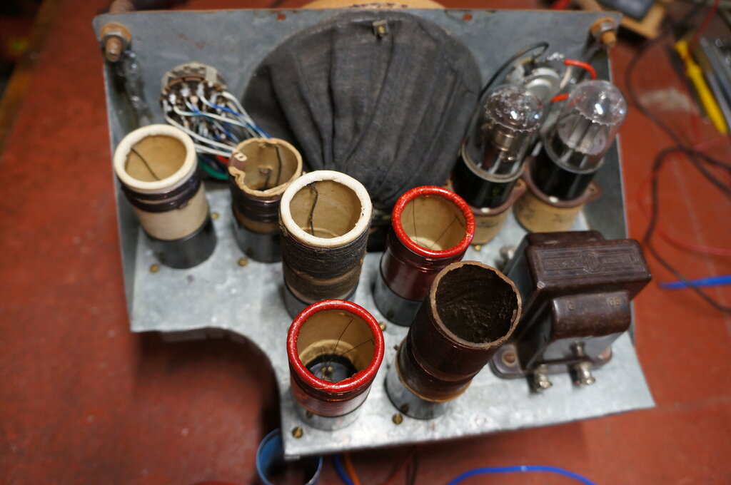
Soldered Chassis.
The chassis had all been soldered together,
rather than using nuts and bolts or rivets. The material is galvanised
steel. Unfortunately, the soldered joints had not taken properly, with
the actual joins being only along the seams, rather than between the pieces
of steel. This meant that after its journey through the post, the whole
thing was coming apart. I attempted reflowing the solder, but clearly the
whole thing would have to be taken apart, the joints cleaned and fluxed
to do it properly. My preference would actually be to clean all the solder
off and use nuts and bolts. A coat of paint would really make an improvement
as well.
Chassis tilted up towards the right. It had been built like that.
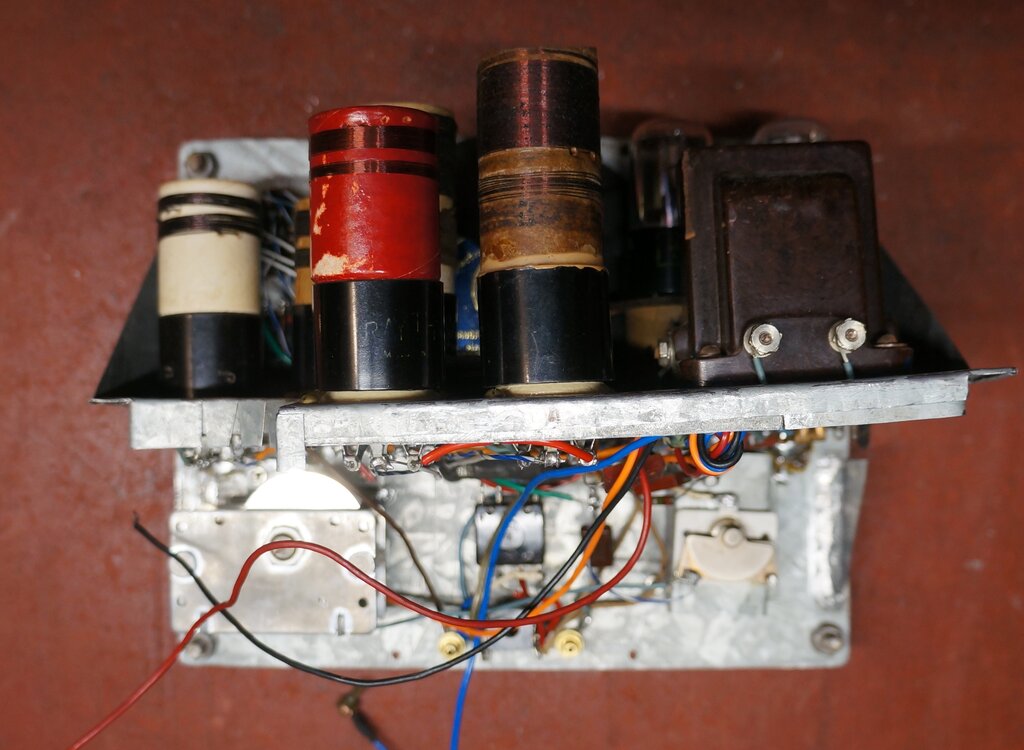
First Impressions.
The first odd thing was, why six coils
to cover the MW and SW bands? Most sets do that with three or four coils,
covering 550Kc/s to 30Mc/s. The band switching was a two stage arrangement
with a three way rotary switch, and a two way toggle switch. More than
likely, this was because a six way rotary switch had not been available.
The coils were all mounted on UX-4 bases.
What was obviously the MW coil had been
wrapped in friction tape. I thought this might reduce the Q.
The "A" battery was intended to be a No. 6 dry cell, from the shape and size of chassis cutout to accomodate it. A larger bracket in the cabinet secured an unknown "B" battery.
Heater voltage was obviously 1.5V.
Another toggle switch had something to
do with the speaker and headphone socket; this being a standard 1/4" type.
The third toggle switch was assumed to be the battery switch.
Regeneration control was by a potentiometer
used as a rheostat - assumed to be of the shunt control type of circuit.
A pair of large vernier dials completed
the controls; one for a large variable condenser of about 400pF and the
other being for a small two fixed plate variable condenser, used as a vernier
tuning control.
Unfortunately, the numerous coils and the complicated switching arrangement had meant the layout was very poor, from an RF perspective. Multiple long wires running to the switch from each coil, was a recipe for instability and dead spots, worsening as the frequency increased.
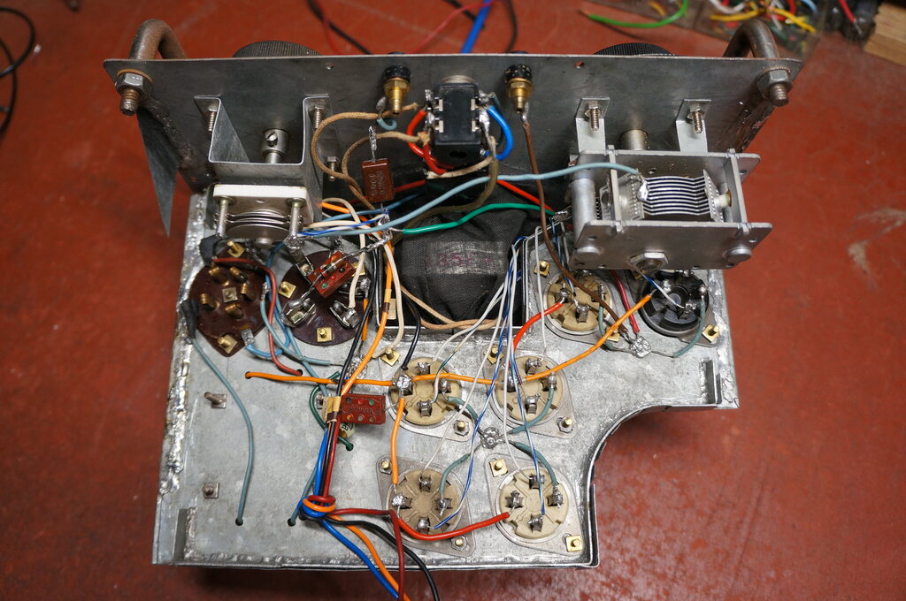
Poor layout with long wires live at RF adjacent to each other.
The valves were also a point of interest. The sockets fitted to the chassis were UY-5 types, which happen to suit type 49 valves. However, both sockets were occupied with home made adaptors, which accomodated a 1Q5 for the detector, and a 3Q5 for the audio valve. These are both octal valves. One could assume the set might have been built as a variant of the Hiker's circuit using 49's, but later fitted with octal valves. On that basis, I thought it would be a low B+ voltage design. Indeed, Lance had tested it with 18V.
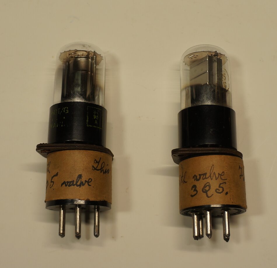
Adaptors for fitting the 1Q5 and 3Q5 into the UY-5 sockets.
Initial Tests.
The set was completely unusable at first
power up. While some MW stations could be received, regeneration was impossible,
even with up to 30V B+. The detector could not reach oscillation. Thinking
about the friction tape, I removed that, but still no joy. I did notice
the feedback winding had less turns than I would have expected. One of
the other coils brought forth a few stations. It could only oscillate over
part of the band.
Where the other coil did oscillate it
was critical, and I was puzzled why the connections on the regeneration
control pot were reversed. I find reversed operation of regeneration controls
unnatural, so I swapped the connections. This helped somewhat, but still
no MW oscillation; even if the MW coil was plugged into the socket closest
to the switch. Even with no aerial loading, it still wouldn't oscillate.
At this point it was time to trace out
the circuit, to see what I was actually dealing with.
The Circuit.
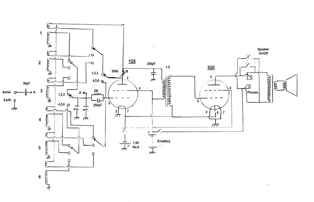
Circuit of the two valve receiver. Valve pin numbers are for the
1Q5 and 3Q5 respectively; not the UY-5 sockets.
The first strange thing was the wiring
of the UY-5 valve sockets. If this set had been constructed to take 49's
operating in space charge mode, there were two problems. The most obvious
one was the grid connections were conventional for tetrode use, and not
for
space charge mode. That is, the signal went to the first (inner) grid,
with the second (outer) grid connected to B+. Looking through a valve manual,
the only two valves with that base and connections, which could have worked
with a low B+, were the audio output types 1D4 and 1F4.
The other thing against 49 valves being
used with best efficiency, is that there is no adjustment for the inner
grid bias, which is simply full B+. While results will be produced thus,
it's not as good as it could be.
The adaptors for the 1Q5 and 3Q5 had been
wired conventionally, so that the control and screen grids were connected
in the normal way. This is correct for low voltage B+ with these valves.
Not knowing what the B+ should be only added to the mystery.
It seemed very unlikely that the B+ would
be much above about 18V, since the output stage has only -1.5V bias.
My guess is that the constructor built the set intending to use 49's, and got the grid connections mixed up from assuming conventional operating conditions. Discovering poor performance, he decided to try the *Q5 types - which do work in the conventional way. Even so, the set still wouldn't have worked properly....
Detector.
The regenerative detector is conventional,
although poorly designed. The main problem is there is no primary winding
for each of the coils. Instead, the aerial is capacitively coupled into
the grid windings. Since the reactance of the aerial coupling capacitor
changes with frequency, the amount of coupling varies as the set
is tuned across the band. Aerial loading effects are magnified, since the
capacitance of the aerial, in series with the coupling capacitor, is across
the tuned circuit. The end result is weaker signals at the low frequency
end of the band, and possible dead spots with inability to achieve oscillation
throughout the band. This is all dependent on aerial characterstics.
In this instance, the coupling capacitor value of 50pF is rather high, and likely to be very problematic at the upper end of the SW bands, unless the aerial is very short. Even in the MW band, a long aerial will be too much loading. If one must use this method, a separate capacitor for each coil would have allowed a more appropriate value for each frequency range. However, it would also require an extra switch pole.
The main tuning capacitor looks to be about
400pF, and in parallel with this is a two fixed plate variable capacitor
for fine tuning. It's a bit of overkill, since vernier dials are already
being used for both condensers. The grid leak is conventional with a 2M
resistor and 250pF mica capacitor.
Feedback is through a second winding on
each coil, which is in the plate circuit of the detector. On its own, oscillation
would occur, but this is throttled back by shunting the coil with a variable
resistor. Again, this is a conventional circuit. However, the value chosen
of 500k is too high for smooth and even control. The detector audio load
is the primary of an interstage audio transformer. Plate RF bypassing is
performed by another 250pF capacitor to earth.
Operating conditions of the 1Q5 are conventional for this application.
Band Switching.
Apart from the question of why so many
coils, the band switching should have used a six way switch. It would appear
our constructor was not able to procure such a component, so used two separate
switches. The rotary switch is 3 position, 4 pole. Using this in conjunction
with a 2 pole, 2 position switch provides the equivalent of a 6 way 2 pole
switch.
The way it works is that the grid windings for coils 1, 2, and 3 are connected to contacts 1,2, and 3 of one pole of the rotary switch. Next, the grid windings for coils 4,5, and 6 are connected to contacts 1,2, and 3 on the second pole of the rotary switch. The wipers of the two rotary switch poles then go into the two way toggle switch. Thus, the common terminal of the toggle switch can select between coils 1,2,3 or 4,5,6. The principle is the same for the feedback windings.
So many coils, yet so little frequency coverage!
Audio Stage.
The transformer is a 5:1 type, connected
so that it steps up the 1Q5 plate signal voltage. Its secondary feeds the
grid of the 3Q5. Apart from the heaters, these two valves are the
same, and with the supplied adaptors, can be plugged into either of the
UY-5 sockets. The 3Q5 adaptor is of course wired for a 1.5V heater supply.
Grid bias is -1.5V taken from the A supply.
The 3Q5 plate feeds a speaker with attached transformer, as well as a headphone socket. This has normally closed contacts wired in series with the speaker, so that when the heaphone plug is inserted the speaker is disconnected. A two pole toggle switch allows the contacts to be bypassed, providing for both headphone and speaker reception. Again, the operating conditions make a B+ of 45V or more unlikely, since headphones would be damaged by the amount of plate current flowing at such a voltage.
It would appear the set was based on the Hiker's circuit with this
amplifier added. However, the valve sockets in the set are not wired for
space charge operation of 49's. This circuit shows a B+ of 15V for both
plate and inner grid.
Another two pole switch performs the on/off function for the batteries. An odd feature is B+ switch only controls the 3Q5 plate supply. Both screen grids and the 1Q5 plate circuit are live at all times. It is true that simply switching off the heaters is enough to stop B+ current flow in a set like this. There's no shunt resistors to otherwise draw current. Also, the B+ is low enough that electrolysis in the interstage transformer windings shouldn't be a problem. But, why bother including the B+ switching when it only controls the 3Q5 plate? I think it's a wiring mistake.
Getting it to Work.
In view of the circuit design, the detector
section with a 1Q5 valve would be optimum for 9 to 18V operation. The audio
stage would obviously work better with 18V than 9V, so 18V was chosen as
the B+ voltage.
Since No. 6 cells are difficult to get
now (and the one in the photo is discharged), a pair of paralleled D size
alkaline cells would suit the 200mA drain at 1.5V. (No.
6 cells are mentioned here). I used a bench power supply to provide
the 18V B+.
The approximate frequency range of each
band was tested with a signal generator. This was coupled into the receiver
via a low value capacitor of 15pF to minimise loading. Because of the regeneration
being largely inoperative, it was necessary to use a fairly high signal
strength of several millivolts at least.
| Band | Frequency (Mc/s) |
| 1 | 0.56 to 1.38 |
| 2 | 1.37 - 2.89 |
| 3 | 1.74 - 3.73 |
| 4 | 1.75 - 3.9 |
| 5 | 3.1 - 6.57 |
| 6 | 4.66 - 9.6 |
Regeneration.
First thing to do was to get it to oscillate
on the MW band, to see what the set was capable of. This would entail more
turns on the feedback winding. But, as a quick test, I simply inserted
a ferrite rod into the coil so as to increase the coupling. It readily
oscillated then, and quite good speaker reception was possible. The catch
was that inserting the ferrite rod also increased the inductance, so the
tuning range was more restricted.
There were only 11 turns for the feedback winding, so I added more to bring up the number to 35, as per the original specification. Interestingly, the holes for the feedback winding wire in the coil former were spaced apart for 35 turns. It's as though the constructor had originally wound it for 35 turns, but later removed 24.
With 35 turns, the detector oscillated easily across the MW band. Not surprisingly, with the regeneration control being too high in value, adjustment was critical with some backlash. Nevertheless, it was possible to confirm the sensitivity was normal. Audio output power, at a guess, would be a couple of milliwatts. It's satisfactory for a quiet room with a strong signal.
The other bands were tested for oscillation. Band 2 oscillated satisfactorily. Band 3 would oscillate across the band, but with a dip - this being because of the Band 1 coil mounted adjacent. Here we see one of the faults with the layout and the coupling between unused coils. Bands 4, 5, and 6 also oscillated. Dips were evident but could not be traced to a particular coil. In any case, the aerial coupling had to be reduced to 15pF or less.
What about 49's?
The final test was to try the circuit
with 49's with the valve sockets as wired. It did actually work despite
the 49's not wired for space charge mode, and regeneration was possible.
However, volume was noticeably less.
Possible Improvements.
Essentially, this set needs a complete
rebuild as per the following: