This receiver is based on the well known
"Little Jim's Mate" which appeared in Radio & Hobbies for May 1939
and was reprinted in several later issues. The circuit is designed around
a 1J6 twin triode. This is the octal version of the 19 which appeared in
the 1930's for use in battery sets as a class B output valve. It can put
out 2.2W with a supply of 135V. Used in class B, the idling current is
10mA which rises to 30mA at full output. The heater requires 2V at 240mA.
There is a similar valve, the 1G6, seldom seen in Australia, which has
a 1.4V 100mA heater. However, its output is only 350mW. These valves are
operated with zero bias...something that people used to valve technology
may find hard to believe. Operating a conventional output triode or pentode
with no bias would result in high current flow and damage to the valve,
let alone provide a distorted output. The grids of the 1J6/19/1G6 are so
constructed to allow the different operation. One important point that
this leads to, is that using this valve in a conventional single ended
power output stage gives mediocre results, even with both triodes paralleled.
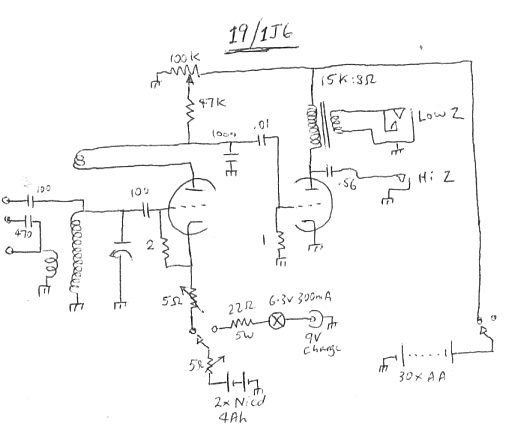
Circuit of the receiver. It is a simple grid leak regenerative detector
which feeds an audio stage to provide good headphone volume. The 5R connected
directly to the 2.4V battery is a preset type adjusted so the valve never
receives more than 2V on the filament. The other 5R is the panel mounted
rheostat.
Detection and audio amplification.
As can be seen from this circuit, the
triodes are being used in the conventional way, with one half performing
as an ordinary regenerative grid leak detector. The other half amplifies
the detector output and drives the headphones. I've adapted the "Little
Jim's Mate" circuit to use potentiometer control of regeneration, rather
than a variable condenser. This method gives smoother regeneration with
no backlash and no detuning of the receiver. Also, a potentiometer is easier
to get and mount on the chassis.
Turning now to the circuit, the tuned
circuit is fed into the grid leak consisting of the 100pF and 2M resistor.
This bit of circuitry in conjunction with the diode formed between the
grid and cathode provides AM detection. Note that the 2M is fed from the
positive heater pin. One can experiment with connecting to the negative
pin instead, but generally receiver performance is improved as shown. Presumably,
this is because the grid to cathode diode is slightly biassed on and therefore
conducts on weaker signals. Ignoring the feedback winding for now, the
detected audio is amplified by the triode and appears at the plate. Resistance
coupling into the next stage is used in the normal way. The 47K is the
plate load for the detector triode and this feeds the output triode grid
via a .01uF condenser to isolate the DC component. To complete the following
grid circuit, a 1M resistor is used. Residual RF is prevented from being
fed into the audio stage by means of the 1000pF bypass condenser connected
to the detector triode's plate.
A much greater audio signal appears on
the plate of the second triode, sufficient to drive headphones at very
good volume. On strong signals in a quiet room, loudspeaker operation is
possible. The speaker transformer matches the high impedance triode to
the low impedance headphones or speaker. It can be dispensed with if using
high impedance magnetic headphones.
To allow for different lengths of aerial,
three terminals are provided. Medium length aerials are connected straight
to the aerial coil primary. Very long aerials are connected to the primary
via 470pF. This is necessary if the aerial resonates in part of the MW
band preventing regeneration. Where only a very short aerial is available,
this connects to the aerial coil secondary via 100pF. Typically, this would
be a couple of metres of wire. Note that connecting the aerial in this
way detunes the circuit because of the capacitive loading, and if the aerial
is too long it may not be possible to achieve oscillation.
Regeneration.
For those unfamiliar with the concept
of regeneration, it works as follows. The receiver described so far
would have poor sensitivity. In fact, it would be no better than a crystal
set with a couple of stages of audio amplification. However, by using positive
feedback we can improve on this considerably, and sensitivity can be brought
up to the background noise level. This kind of sensitivity allows interstate
and worldwide reception.
The first triode not only amplifies the
audio, but also the RF signal as selected by the tuned circuit. If we feed
a portion of this RF back into the tuned circuit, via the third winding
on the aerial coil, the signal at the grid becomes even stronger. This
strengthened signal is fed into the triode grid, amplified again and made
even more powerful before being fed back into the grid. And so the this
process continues to repeat itself resulting in considerable amplification.
However, the laws of physics tells us we can't have something for nothing,
and the point is reached where the circuit has amplified its own signal
so much that it becomes unstable and breaks into oscillation. This is what
gives regenerative receivers their characteristic squeal when incorrectly
adjusted.
Regeneration also increases the Q of the
tuned circuit immensely and thus improves selectivity. With regeneration
adjusted correctly, I can receive 2ZB from Wellington, NZ, on 1035Kc/s.
This is without much interference (sometimes none) from Sydney's 2KY on
1017Kc/s.
The key to the regenerative receiver is
to be able to control the positive feedback so that the receiver is just
about to break into oscillation, but doesn't. Many methods are used. Popular
in Australia and Europe is to use a small variable condenser in series
with the feedback winding. With the plates meshed, the reactance is low
and more current can flow through the feedback winding, and vice versa.
However, it can be imagined that another variable condenser connected to
the tuned circuit will have some influence on the receiver's tuning, and
indeed it does. The main tuning requires touching up as the regeneration
control is adjusted.
In the U.S., controlling regeneration
with a potentiometer seems to be the more common method. One way is to
use the potentiometer as a variable shunt across the feedback winding.
Whilst it works, it does so by lowering the Q of the tuned circuit. It
is also critical in adjustment and has bad backlash. The proper method
is to use the potentiometer to control the gain of the detector valve.
This results in smooth regeneration, and as the tuned circuit has nothing
to do with the potentiometer, the circuit does not require retuning as
the regeneration is adjusted.
Another less used method is to vary the
physical coupling between the tuned circuit and feedback coil. It works
very well but is not often seen outside of 1920's designs.
In this circuit the detector gain is adjusted
by varying the plate voltage by means of the 100K potentiometer across
the 45V B+ supply. There is a similar circuit popular in the U.S called
by such names as "Twinplex" which also uses a 1J6/19/1G6 and it controls
regeneration in the same way.
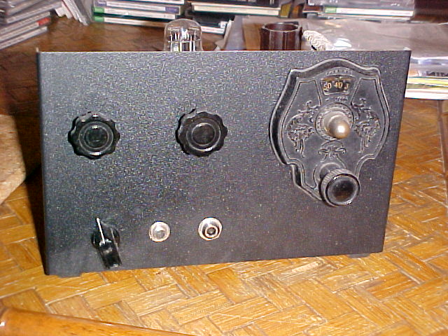
The array of aerial terminals provides for differing aerial lengths.
To the right is the A battery charge input socket.
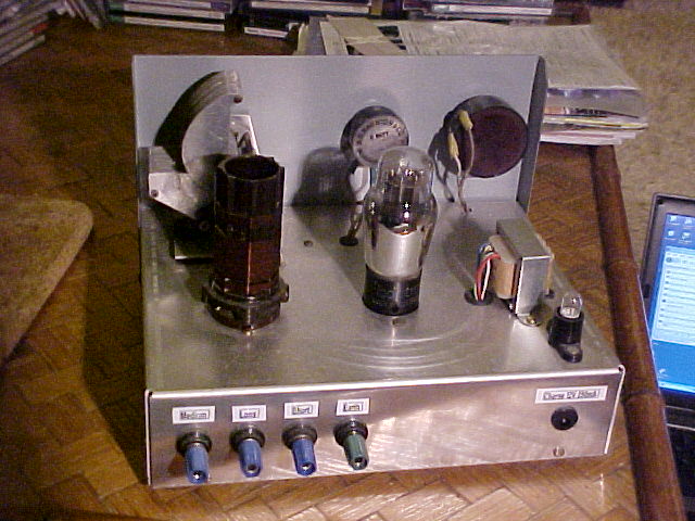
Constructional Points.
As can be seen, I built the circuit up
on an aluminium chassis with a Marviplate front panel. However, it can
also be built on just a piece of plywood. This kind of construction is
acceptable for simple receivers like this as gain is not so high as to
cause instability. The frequencies involved do not require critical layout
or shielding. In fact, wooden baseboard construction was standard up until
about 1929. For a project like this it certainly allows ease of experimentation.
If building on a wooden chassis, it's easiest to use 1J6 which will allow
an octal relay socket to be used for the valve. These are ideal for this
construction as they can be mounted directly to the baseboard and have
terminals facing up. If you're using a 19, you'll have to use a conventional
6 pin chassis mount socket on spacers.
Power Supply.
The valve needs a heater (A) and plate
(B) supply to work. The heater requirements for the 1J6 or 19 are 2V at
240mA, while the 1G6 requires 1.4V at 100mA. The 1J6/19 was intended for
receivers where a single cell 2V accumulator was used for the A supply.
Some such sets ran off a 6V accumulator but the heaters of the valves were
arranged in series/parallel to allow this. The 2V accumulator would run
a typical set for several weeks of intermittent use before it had to be
recharged. The 1G6 however, was designed for dry battery operation. The
A supply battery for such a set would consist of a number of 1.5V cells
mounted in a cardboard box all connected in parallel, or sometimes a few
No. 6 dry cells in parallel. Dry battery sets consumed less heater power
than their wet battery equivalents, so a domestic receiver might only need
the battery replaced every six months. This came about when the 1.4V valves
appeared in the 1940's for portable sets, where reducing power consumption
(and battery size) was crucial to their design. Initially, they were
octal valves but were then replaced by 7 pin miniatures thus giving rise
to the usual 1R5, 1T4, 1S5, 3V4 lineup that existed until transistors took
over in the late 1950's.
For this set, a number of options are
possible. I've used a 2.4V 4Ah NiCd battery. This requires 400mV to be
dropped before being applied to the heater. This is the purpose of the
5R preset resistor. You could use a pair of alkaline cells in series, providing
3V. Alkaline D cells have a very high Ah capacity so would be quite suitable.
The resistor then needs to be 4.2R. Two 8.2R's in parallel would probably
be close enough, but whatever scheme is used, see that no more than 2V
is applied to the heater. If you have a 1G6, then obviously one alkaline
D cell would suffice with no series resistor. Of course, if you have one,
a lead acid 2V accumulator can be used. These are still available as the
well known "Gates Cell". If using rechargeable cells do not charge while
the heater is connected, as the higher voltage could be detrimental.
In this circuit, the 1J6 or 19 will work
off a 1.5V supply. The main difference is slightly less power output. Given
the extremely low cathode current, there is no risk of cathode poisoning
by running the heater at reduced temperature.
In fact, some useful economy can be had
by including a filament rheostat in series with the A battery. I found
that either a 5 or 10 ohm type was the most suitable.
When full power output isn't required,
the heater voltage can be reduced, thus reducing current and lengthening
the time between battery recharge or replacement.
Even with only 1V on the heater, the set
regenerates, but audio output is low. If such a rheostat is included, see
if it has any residual resistance when in the minimum position. In this
situation it may be necessary to reduce the heater resistor. Again, see
that the heater voltage does not exceed 2V at any setting.
The B+ supply only needs to provide just
over 1mA, so there's a wide range of options here too. The obvious one
is to make up a 45V battery with five 9V batteries in series. Given how
cheap AA or AAA cells are now, connecting 30 in series is also an option
and such a battery would last for an extremely long time. I've used 30
AA cells in this set, which should last until they start leaking. An inverter
to run the set from the A battery alone appears to be practical after
trying some experiments.
B+ voltage is not critical. Although the
set can be made to work with lower voltages, the power output suffers.
45V is what I consider to be the minimum and is what I designed the set
for. This gives very good headphone volume. If you want to run the set
into a speaker at greater volume, then go up to 90V. No modifications are
needed, although if this is to be permanent, I would recommend increasing
the potentiometer value to 250K and the plate resistor to 100K. This will
allow higher audio gain and the B+ bleed current will be reduced.
The power switch must be a double pole
type to switch both the A and B batteries. Even though the valve does not
draw plate current when the heater is turned off, there will still be a
drain on the B battery because of the 100K pot. Make sure you do not mix
the connections or the valve heater will be blown in the blink of an eye.
It is good practice when building a battery valve set and operating it
for the first time to connect the A battery first and see the heaters work
before applying the B+. Note that battery valves do not light up like their
mains counterparts. In fact, with ordinary room lighting they are almost
impossible to see. The 1J6/19 with its higher current filament can be seen
if one looks carefully into the valve from directly above. This assumes
its heater is running off 2V and not 1.5V. If you are attracted to valve
circuits only because of the bright glow of large amplifier valves, you
will be disappointed playing around with battery types.
Since I'm using a rechargeable A battery,
I've also included an input socket from a 9V plugpack, A 6.3V 300mA light
bulb and 22R resistor limits the charge current. The switching is arranged
so that the charging can only occur with the set switched off. This is
to prevent the 19 filament from being exposed to the slightly higher voltage
as the battery is being charged.
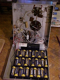
30 AA cells in series provide 45V for the B+. Two D size NiCd cells
provide the A supply.
Audio stage.
As mentioned before, high impedance headphones
can be used. These are the kind that have a resistance of around 2000 ohms,
uncomfortable bakelite earpieces, a tight headband, and an appalling frequency
response. Because I like good sound quality, I use modern stereo headphones
with a transformer. Be wary of cheap headphones; some are rather insensitive.
Unless you have a high impedance horn
or magnetic speaker, you'll require the transformer for speaker operation.
The most suitable primary impedance is around 10K to 20K. Like many of
my valve projects, I use a 100V line transformer for an output transformers
as these have the same impedances used in valve circuits. Such transformers
are common in speakers used in P.A. systems.
Here, I've used a multi tapped line transformer.
Best output was obtained using the .66W tap, which corresponds to 15K impedance.
A multi tap transformer allows a bit of experimentation here. The phones
or speaker are fed off the 8R secondary in the usual way. Obviously, for
stereo phones, each channel is connected in parallel. Common 5K or
7K valve output transformers will work well but with slight reduction in
power output. Also possible is using a mains transformer with suitable
turns ratio. Provision is made for high impedance phones by coupling them
to the plate via a .56uF condenser.
I have experimented with an additional
amplifier stage to drive a speaker with greater power. It also uses a 1J6
with triodes in parallel. Although it is not making the best use of the
1J6's power output it is simple and provides fairly good results. To use
the 1J6 in class B requires centre tapped driver and output transformers,
and a drive power of 170mW.
If you find it desirable, a volume control
can be added simply by replacing the 1M grid resistor with a 1M pot. The
wiper of the pot then feeds the grid. It is not good practice to reduce
volume by means of the regeneration control as selectivity is reduced.
RF Section.
The aerial coil can be wound on a 3/8"
or 10mm ferrite rod. It is essential that whatever method of mounting the
ferrite rod is used, that it does not result in a shorted turn around the
coil. Some methods of mounting include using plastic cable clips
of the type used to secure flexible mains cables, or small spring clips
normally used to secure screwdrivers on a toolboard. If using these, see
that the ends do not touch. For use with a 415pF tuning condenser, about
55 turns of enameled copper wire is required of about 26 gauge. It
isn't critical and a gauge or two either way is acceptable. The aerial
winding is about 7 turns and the feedback winding 11 turns of similar.
Important to note that if the feedback winding is not connected correctly,
the set will be extremely insensitive and will not regenerate. If you wish
to make an air cored coil, as used here, see the coil data from the Tiny
Tim II. Or you can use a commercially made Reinartz coil. A commercially
made ferrite rod aerial with 180pF tuning condenser can be used of course.
These have a second winding intended for feeding the base of the frequency
converter transistor in a solid state radio. This winding can sometimes
be used as the aerial input or feedback winding.
Getting the set operational.
With aerial and earth connected (if using
an air cored coil) and the regeneration pot wound all the way up, whistles
should be heard as the set is tuned across the band. The ferrite rod aerial
will work in strong signal areas on its own, but is much improved by providing
an earth connection. The whistles indicates the regeneration is working.
Backing off the control to just before oscillation occurs will allow
clear reception. Note that the regeneration needs to be readjusted for
each different frequency. If you have any ideas about using this set for
short waves, it will demodulate SSB and CW if the regeneration is adjusted
just past the oscillation point. Incidentally, it is possible to use a
regenerative set like this as a simple transmitter, as when oscillating
it radiates energy up the aerial. By inserting a morse key in the B+ circuit,
and winding the regeneration up to maximum, you then have a CW transmitter.
Now it's time to optimise the set. First
see that the regeneration occurs over the entire band. If it doesn't, turns
may need to be added to the feedback winding.
Too many turns and the regeneration control
has to be operated backed almost right off. This is not a good thing as
plate voltage on the detector is too low, resulting in low audio output.
You also need to allow for battery discharge in determining the amount
of turns. I've allowed for regeneration to occur across the band with the
battery as low as 30V. That way, battery life can be extended. With the
aerial connected (and thus loading the coil), put on enough turns so that
with the wiper of the pot set to 30V regeneration is reliable over the
band. Do not put on more turns than required to achieve this.
For aerial coupling, this is a compromise.
Too many turns and selectivity may be poor and regeneration may not occur
over the whole band. Too few turns and the receiver has poor gain. Adding
tappings to the main coil can be useful.