Originally published in Radio and Hobbies
in Australia, April 1943, the Tiny Tim 2 is one of the simplest mains operated
receivers. A regenerative detector feeding an output pentode provides good
speaker volume on most receivable stations.
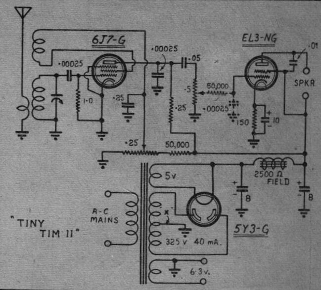
A trap for those not familiar with valve circuits and Australian
circuit diagrams of the period; the terminals marked "SPKR" are for feeding
into the output transformer (7000 ohms for the EL3NG), not directly into
the voice coil.
The 6J7 (modern equivalent is 6AU6) functions
as a regenerative grid leak detector with the feedback winding fed from
the screen grid, rather than the plate or cathode as seen on other circuits.
In effect, the screen is functioning as a plate as far as the feedback
winding is concerned, with the detected audio taken from the plate in the
usual way. The coil is a commercially made Reinartz type marketed in Australia
by firms such as RCS radio, or it can be made to the following specifications:
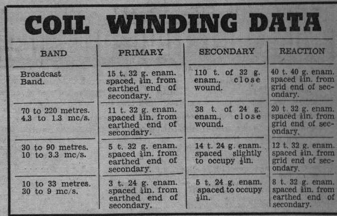
Coils are wound on a 1.25" (32mm) former.
The receiver was intended to have the coils
on plug in formers for changing to the other bands. Data is given for reception
up to 30Mc/s. Although I made my receiver for MW only, I used a plug in
coil former because I had the genuine type on hand.
The detected and amplified audio then
feeds into an EL3N output valve. For those outside Australasia and Europe,
this is a high gain pentode of Philips design. I has roughly twice the
gain of a 6V6. Although it's pin compatible, the bias is less and the load
impedance is 7K instead of 5K. Power output is also a fraction less. The
9 pin equivalent is 6M5 (EL80) which was used in thousands upon thousands
of Australian radios. Due to the high gain, a grid stopper resistor is
often required. This, and an associated condenser are shown dotted in the
circuit, to be added if required. Note that this circuit was one of many
published by R&H during the war years when components were difficult
to get, hence the simplicity and being designed around standard kinds of
components.
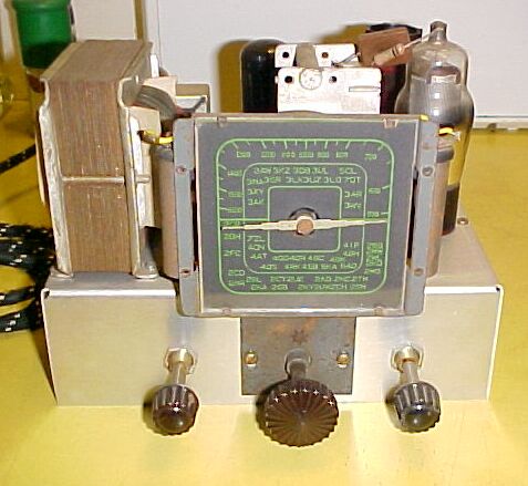
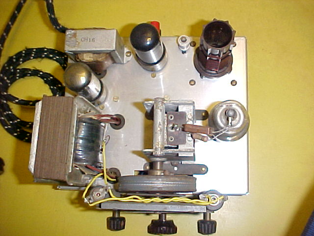
Coil clearly visible in the bottom lefthand corner. Between it and
the 6V6 output valve is the trimmer to set the dial calibrations correctly.
The two aerial terminals are on the left, with the speaker terminals on
the right.
I also had an RCS dial and single gang
tuning condenser as per the original design, so these were pressed into
service.
Essentially, my version of the Radio &
Hobbies design is the same, except I've used a 6V6 instead of the EL3N.
(The cathode bias resistor was of course changed to 250R). Also, as I'm
not using an electrodynamic speaker, a filter choke
filters the high tension instead of a
field coil. And, due to length of my outdoor aerial with its resultant
absorbtion effects, I've added an extra aerial terminal which puts a 470pF
condenser in series with the aerial.
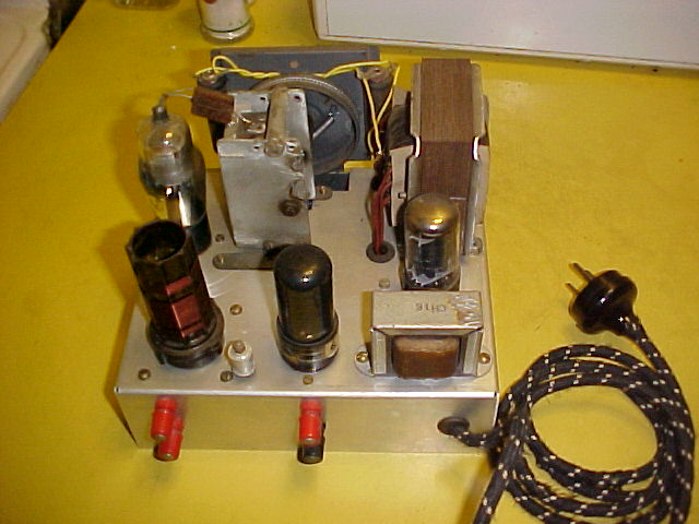
In this pic, the grid leak resistor and condenser are visible connected
to the 6J7 top cap.
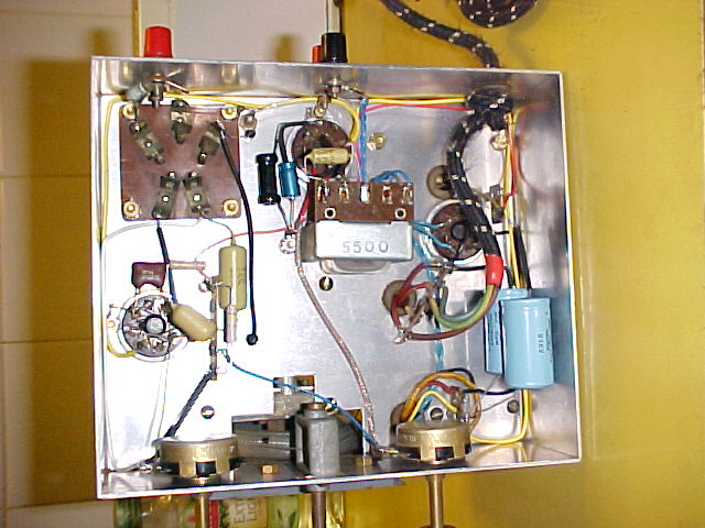
Under chassis view. Speaker transformer is mounted in the centre.
Note the simplicity of the circuit.
Performance is excellent. Even though I'm
using a 6V6 instead of the EL3N, the receiver easily provides good volume.
Regeneration is particularly smooth with
absolutely no backlash. I've never liked the method of regeneration that
involves a variable capacitor in series with the feedback winding. Not
only is there backlash, but it affects the tuning. Besides, the 100pF value
usually specified isn't what I'd describe as a common component. It's more
expensive than a potentiometer too.