One has to wonder how many people would carry a 6V car battery into a hotel room. The concept of an office with no mains supply would be equally hard to imagine in the modern day.
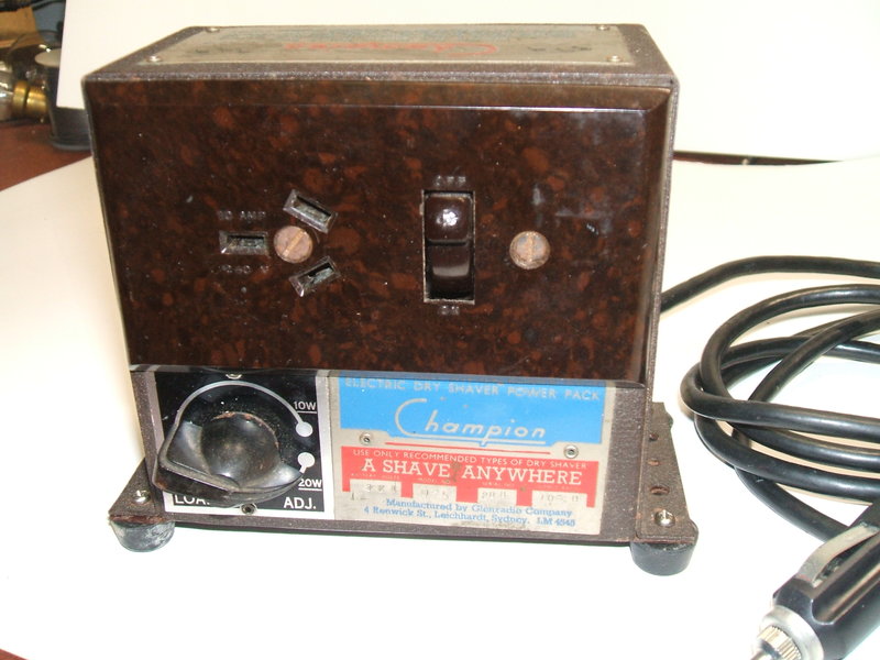
This little inverter was found in a council
clean up in 1984. It is typical of the 1950's shaver inverters that were
popular at the time, and provided 250V DC at up to 20W from 6V DC. Internally,
it contained an Oak type V5124 synchronous vibrator, and a Ferguson VT107,
250V 60mA, vibrator transformer. The circuit had been wired to provide
DC output, and would thus suit motor driven shavers only. The switch on
the power point was used to switch the 6V supply, and a further switch
is provided to select 10W or 20W output. This simply switches in a 1K 5W
resistor in series with the 250V output when 10W is selected, should the
output voltage be excessive under a light load.
At the time, I replaced the .01uF buffer
capacitors, and converted the 6 volt operation to 12V by means of three
paralleled 5.6R 10W resistors in series with the supply. I also rewired
it for AC output. Back then, I had no car with a 6V battery, or any other
high current 6V source, hence the 12V conversion.
Using resistors to drop the voltage was
extremely crude because of the very poor voltage regulation introduced.
With light loading, the vibrator and transformer were exposed to excessive
voltage, as would the appliance running off the inverter. The resistors
also ran very hot which wasn't good with them fitted inside the case. It
was a bodgie set-up and I never really used it. Eventually, I had a need
for a 6V vibrator transformer in another project, so the VT107 transformer
was "borrowed". It failed some time later with shorted turns, possibly
as the result of the earlier running with excess input voltage. The vibrator
was also used elsewhere.
The proper way to have done the 12V conversion
would be to use a split reed vibrator with the existing transformer as
described here. However,
at the time I did not have any such things, and nor did I know about the
concept.
One has to wonder how many people would carry a 6V car battery into
a hotel room. The concept of an office with no mains supply would be equally
hard to imagine in the modern day.
For quite a number of years the inverter remained a largely empty box. The original construction was quite crude. The vibrator had been mounted on the chassis by means of a single rivet through the top of the can. Interestingly, the can and the mechanism inside were not related. The can had a number for a 7 pin split reed 12V type, AV5948, yet the mechanism inside was obviously a V5124, 6 pin synchronous 6V type. It seems that Glenradio must have been supplied with oddment cans and separate mechanisms from MSP. Because of the transformer fouling the back of the power point, about a quarter of the laminations had been removed from the top. No doubt the magnetic circuit was disrupted to some degree. Glenradio must have thought that service access was not required because the chassis and case had been riveted together.
The Rebuild.
Obviously, if I was to rebuild it, it
would be for 12V. My attention was drawn to the small 20VA toroidal transformers
that Jaycar had started selling at the time, because of their small size
to power ratio. It looked like one would fit into the box very nicely,
leaving enough room for the vibrator and other parts. Indeed it did, and
the inverter was rebuilt. I re-installed the original vibrator, but this
time used a strap to secure it to the chassis. The old rubber twin flex
with alligator clips supply cable was replaced with a modern plastic cable,
and this was terminated with an internally fused cigarette lighter plug.
We're going back to the mid 1990's here
when my knowledge of vibrator power supplies was fairly elementary. However,
I selected what I thought was an appropriate timing (buffer) capacitor
value of .1uF and occasionally used the inverter to power small appliances
in the car. The original V5124 vibrator was operated off 12V by means of
a 22R 5W resistor in series with the driving coil. The original 10W/20W
switch was retained, even though the regulation of the new design did not
actually require it.
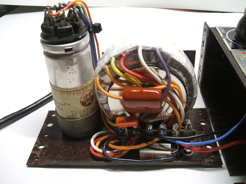
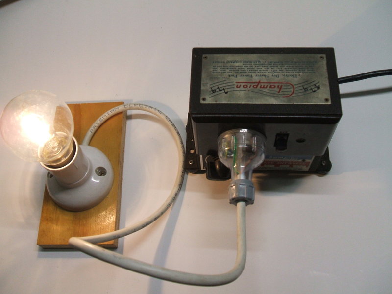
Inverter rebuilt for 12V with a toroidal transformer.
The vibrator was in good condition except for the rubber base and flange having deteriorated. I used a suitably cut up piece of foam rubber to replace it with. The original uninsulated connecting wires had to be replaced as the original rubber base had separate insulated tubes for each wire, and of course my replacement did not. I used ultra flexible test lead wire which allows movement of the mechanism without breaking.
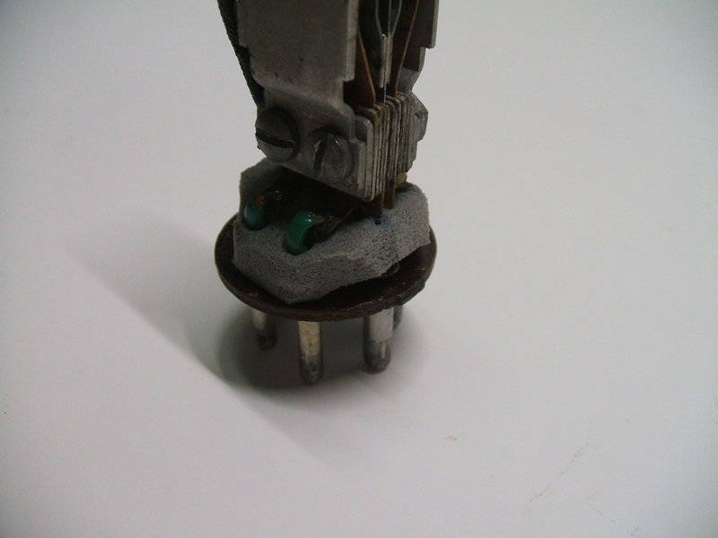
The rubber base of the vibrator was replaced with foam sponge rubber.
Recently, I decided to dig out the Champion,
in view of a long drive coming up and a need to run the Phono
Oscillator in the car. This was to allow me to listen to my iPod on
the car radio. It was an opportune time to check the timing capacitor value
again, in view of my now much greater knowledge of the subject. As
it turned out, a can of worms was opened...
It certainly appeared from the unloaded
waveform that .1uF was excessive. As expected, decreasing the capacitance
decreased the input current at 12V with no load. The strange thing was
that the current kept dropping as I reduced the capacitance. With no capacitance
the current was at its lowest, and the waveform was actually looking much
like it should.
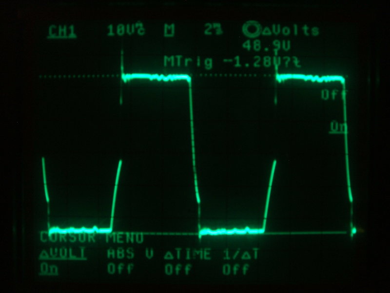
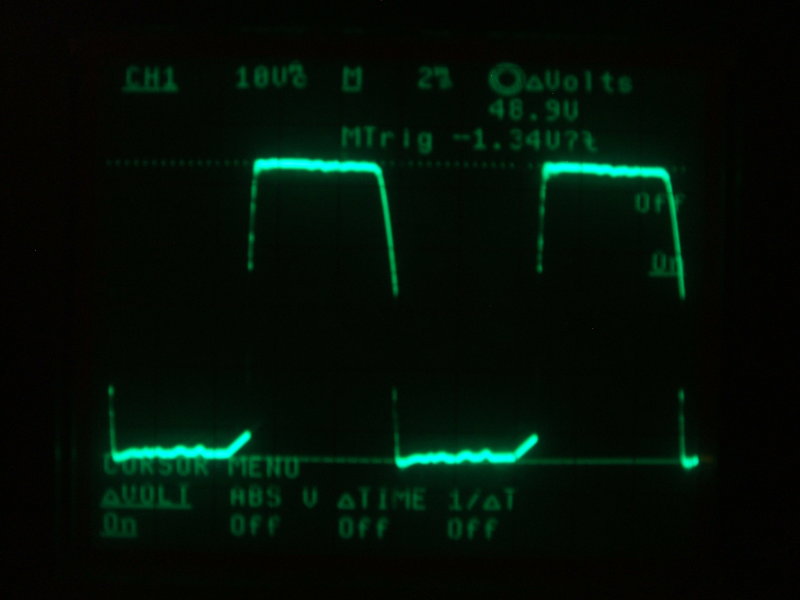
Jaycar 9-0-9V 20VA toroid with no timing condenser. Waveform is
measured across the total 18V CT winding and inverter is unloaded. This
is not far off the ideal waveform.
In fact, if anything the capacitance was still a little high, despite there being no actual physical capacitor. Obviously, the toroid is in another world with its characteristics, and the secondary winding capacitance on its own was more than enough to provide the correct waveform. It seemed quite bizarre that the optimum operating conditions were to run with no external timing capacitance, given the importance which this receives in just about every vibrator article. Yet, this was clearly the correct state of operation, and the transformer contained sufficient capacitance within.
One of the difficulties with DC to AC inverters
is the varied kind of loads which might be plugged into them. Ideally,
an AC inverter is designed to suit a specific load, but in the real world
it has to be a compromise. Capacitive loads have the same effect as increasing
the timing capacitance, and inductive loads have the effect of decreasing
it.
This means the timing capacitance needs
to be the minimum to cope with the most inductive load likely to be used.
However, with other loads the capacitance may be too much. In view of the
damage that will result with insufficient capacitance, it is, given a choice,
better to have too much than too little.
Additional Timing Capacitance.
I tried a variety of low power loads,
and found that items containing transformers did actually have the effect
of reducing timing capacitance. In fact, the light loading of a solid state
radio cassette recorder was enough to cause an undesirable overshoot with
the waveform. With the loads I tested, the one that had the most effect
was the previously mentioned Phono Oscillator. The result was that a minimum
of .033uF was required to be added to the secondary circuit. With this
capacitance, there was a small overshoot at the rising edge of the waveform
which would not be important, but because there was room to include it,
a 680R 1W damping resistor was connected in series.
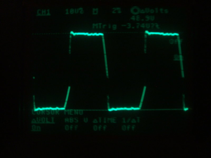
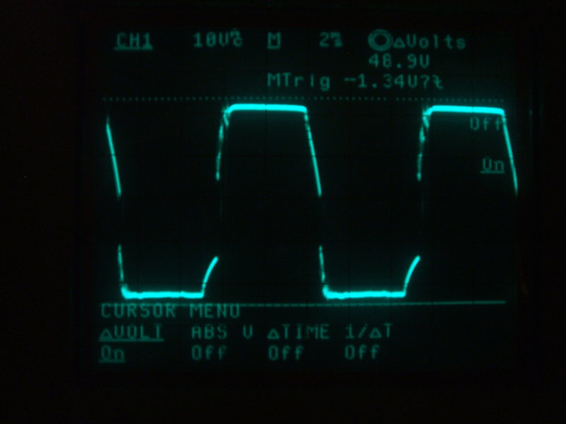
Unloaded waveform with a .033uF timing capacitor and series 680R
damping resistor.
It can be seen from introducing the
.033uF capacitor that the capacitance is now excessive under unloaded conditions.
This is shown by the short 45 degree rise in the waveform at the bottom
of the rising edge.
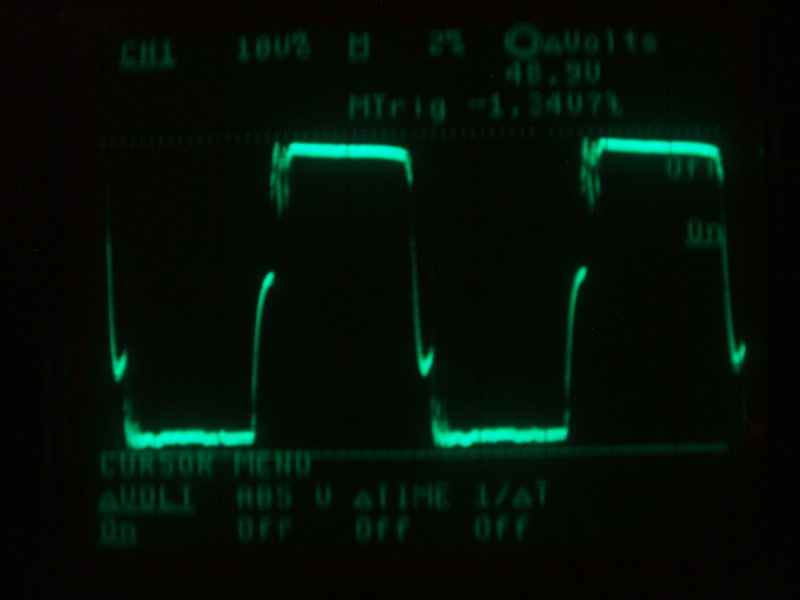
Next, the inverter is loaded by a solid state radio cassette recorder. Now we see the bottom of the rising edge rising more steeply. Here, the waveform is starting to approach the text book standard.
A slightly inductive load (transformer powered radio cassette recorder)
produces this waveform.
The next waveform shows the most inductive load I used for the tests, and that which dictated the timing capacitor being .033uF. It is the Phono Oscillator which contains two transformers. The resistive aspect of the load (valve heaters) is also visible here - the rising and falling edges contain a glitch. This is because the timing capacitance is being discharged by the resistive load.
Inverter loaded with Phono Oscillator. This is substantially a resistive
load, but the loading of the transformer inductance requires more timing
capacitance.
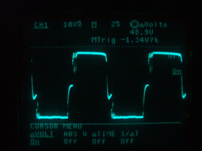
Resistive load discharges the timing capacitance rapidly. This is
why the waveform of an AC inverter is often different to that of a vibrator
supply for a radio.
Inverter loaded with an 11W Compact Fluorescent Lamp with electronic
control gear.
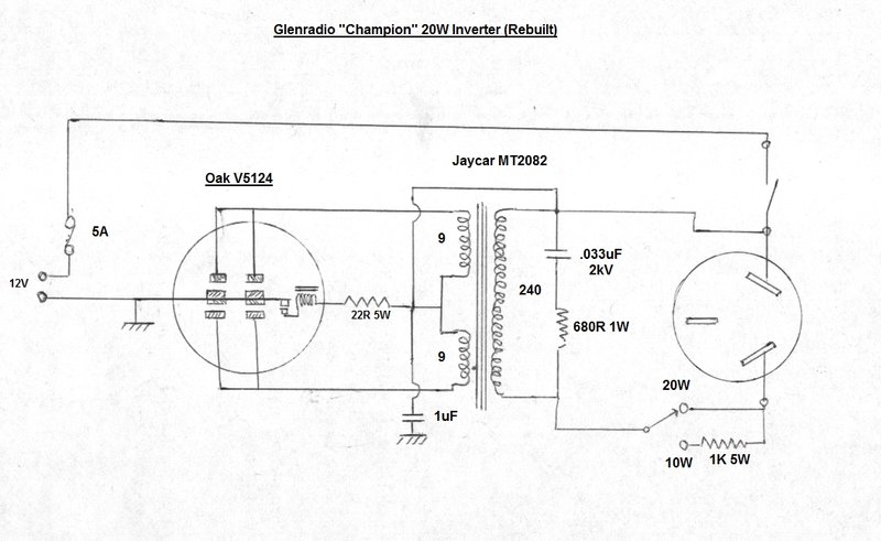
Final circuit after rebuild and correction of timing circuit.
As can be seen, the circuit is very typical
of others shown on this site. To summarise, the original 6V vibrator now
operates on 12V by means of the series 22R resistor in the driving coil
circuit.
Because the vibrator is a synchronous
type, the secondary contacts have been paralleled to those of the primary.
It can be argued that the secondary contacts will have minimal effect in
terms of increasing current rating as they close and open after and before
the primary contacts. It's at the switching time when the contacts are
under the most stress. However, one may as well make use of the contacts
rather than leave them unconnected. As it is, the loading of this inverter
is very light on the contact ratings of the V5124 vibrator.
A Jaycar MT-2082 toroidal power transformer
is used in reverse to step up the 12V to 240V. As explained elsewhere,
it is necessary to use a primary of 9V, rather than 12V, because of the
vibrator's dead time when the reed is in between contacts.
The timing circuit has been explained
previously. A .033uF 2kV polyester capacitor has been used. It is not recommended
to use 250VAC types because their self healing properties cause the capacitance
to gradually reduce over the time the capacitor is used. A reduction in
timing capacitance is highly undesirable in view of the damage it could
cause to the vibrator. It should be pointed out again that the timing circuit
was selected to suit this transformer when used with a variety of different
loads. Only with a certain amount of inductance in the load is the timing
capacitance actually optimum.
The secondary being connected to the 12V
supply may seem unusual, but it comes about because the power switch is
part of the power point. In this application, there is no need to isolate
the two.
Given that most low power appliances do
not have an earth connection, the power point earth was not connected to
anything, and nor was it in the original circuit.
A 1uF polyester capacitor on the 12V supply
provides RFI suppression. The 12V input is non polarised, but the inverter
chassis is connected to one side of the supply, so when used in a vehicle
or other earthed situation, polarity does need to be observed. There is
a 5A fuse inside the cigarette lighter plug for protection in case of excessive
overload.
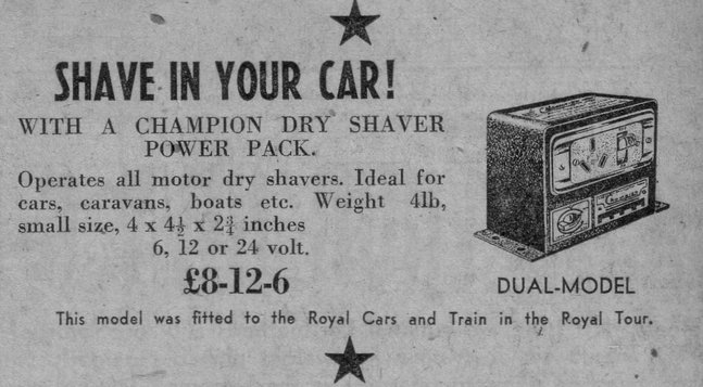
Glenradio advertisement from 1954.