This is the second Vauxhall radio I've restored. Since a lot of the procedure was the same as the previous job, the Astor RM article should be read first.
Like the RL/RM models, the Astor CR (6V) and CS (12V) were used in many different cars, and fitted with appropriate control heads to suit. The most well known use of the CR was the FJ Holden. Astor had the contract to build the radios for General Motors Holden's, which were branded "Air Chief". Since Vauxhall was also a GM product, they were also fitted with Astor/Air Chief radios.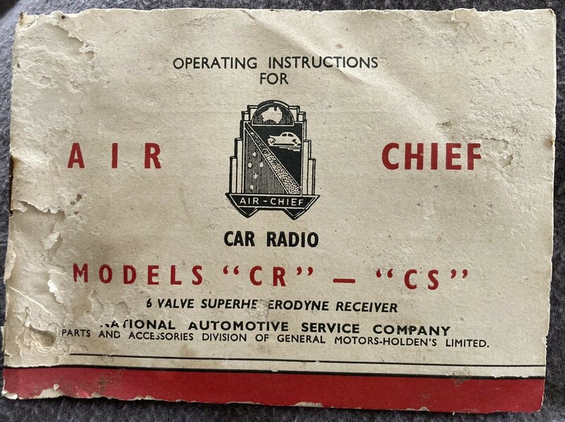
The CR/CS was the predecessor to the RL/RM, and the two sets appear much the same as each other externally. The difference is inside, and is essentially that the CR/CS used a tuning condenser, while the RL/RM uses permeability tuning - which became standard for car radios, right up until tuning with varicap diodes took over in the 1980's.
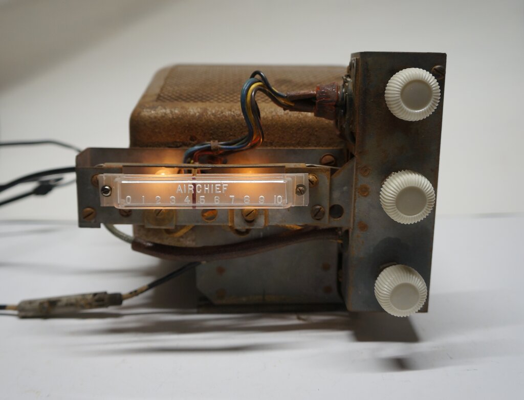
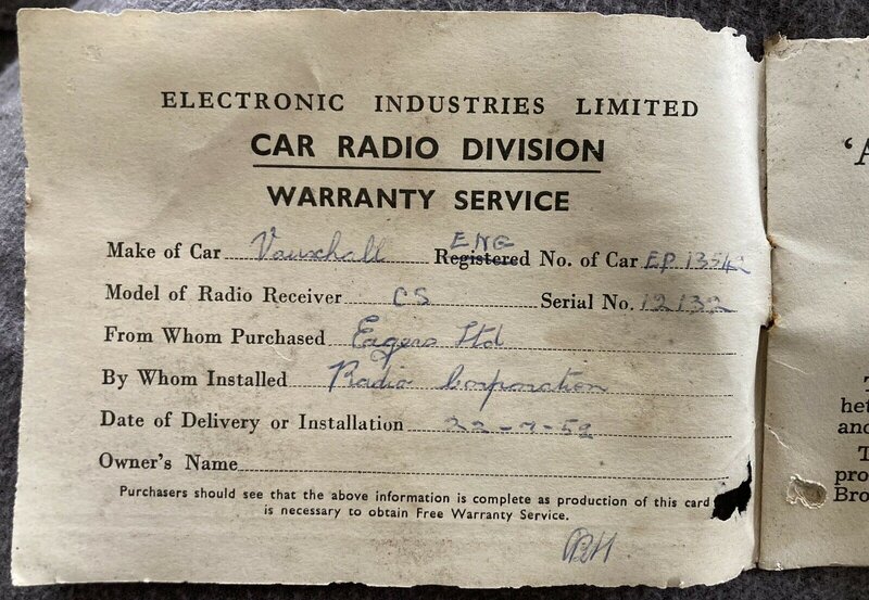
This CS was purchased at a Vauxhall rally by a friend who owns a 1953 Vauxhall Velox. Apart from a damaged dial and missing knobs, it was in fairly good complete condition.
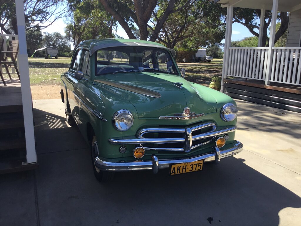
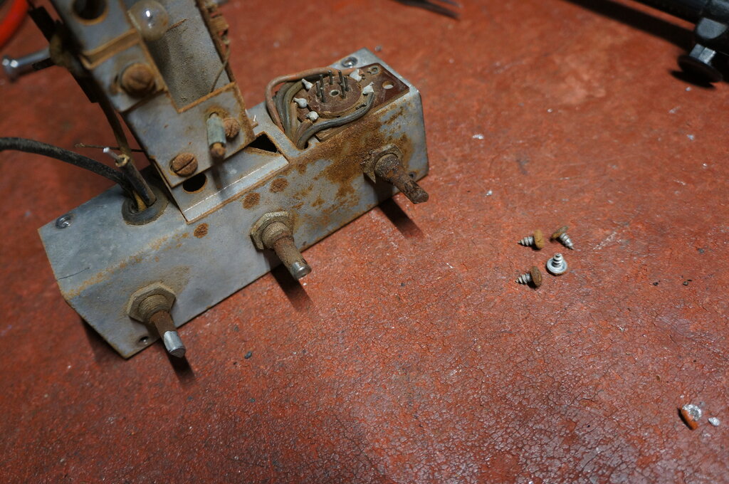
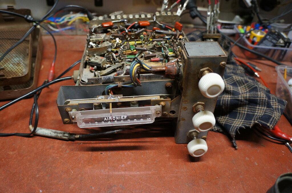
Mounting bracket restricts service access.
Complex Control Head.
I was already familiar with the CR/CS
of course, since a CR was the first Astor car radio I had seen back in
1981, and have accumulated others since. What was interesting with this
set was how it had been adapted to the Vauxhall. As is typical with this
series of Astor car radios, the control head is separate to the actual
radio, and is connected by a rubber coupling for the tuning control, and
a multi-pin connector (in this case a seven pin valve plug and socket),
for the tone and volume controls.
For the Vauxhall, the control layout is
unconventional, with three knobs in a vertical row down the right side
of the dial. A rather complicated control head had been designed by Astor,
with numerous bends and cut outs.
Added to that was a bracket underneath the set, to mount it on the platform of the radio compartment in the dash. Problem with this is there is no access to the valves and vibrator until this bracket is removed. And, to remove it entails removing two screws in the control head behind the dial. Even though there are two holes in the control head to get to these screws, it's still a fiddly operation to remove and replace them.
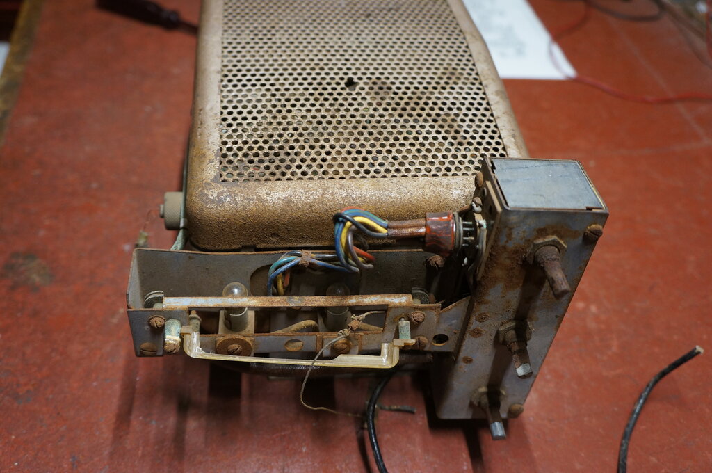
A cheap/rough looking aspect of the whole
thing is that the control head actually screws on to the radio at a slight
angle, because the mounting bracket is under only the bottom two screws.
There is no spacing for the upper two screws, so the control head tilts
up at an angle dependent on the thickness of the bracket. Furthermore,
the back of the control head is bent so that the depth of the whole thing
matches up with the dial surround on the dash.
It's typical of Astor construction, and
has the appearance of something hastily designed and put together out of
whatever was to hand, to make an existing radio work with this particular
control layout.
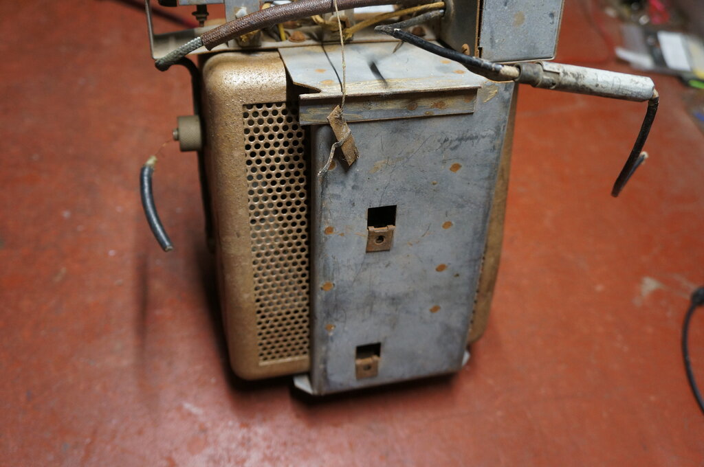
The dial lens itself is stood off the metalwork
by two small diameter bolts and spacers, and the dial cord and pointer
is exposed, making the whole arrangement rather vulnerable. As it was,
the dial lens was broken along with the dial cord, and the pointer was
damaged.
Once however, mounted in the car with
the dial surround in place, the dial is much more protected.
Unfortunately the dial was broken. Not surprising, since it is mounted
in a vulnerable position. Note the two holes under the dial lens to remove
the screws which secure the mounting bracket.
Conveniently, the dial lens and knobs are the same as used for the sets made for the FX and FJ Holdens, among others. This was fortunate, since reproductions are available.
Dial Lamps.
Mounted at the back of the control head
are two 12V MBC based bulbs connected in series to illuminate the dial.
Since the bulbs are in series, it means the socket for one of the bulbs
has to be electrically floating above chassis. To achieve this, the first
bulb socket is mounted off the chassis by a bushing and paper insulator.
The outer connection of the socket is live at 12V, and seems rather vulnerable
to short circuits. It would have been better to feed the 12V into the centre
contact of this socket, so that if the outer connection did short to chassis,
the bulb would simply light up at full brilliance. The way it is manufactured
means the 12V supply is shorted out if the insulator fails.
Inside the enclosed portion of the control head are the tone, tuning, and on/off volume controls, from top to bottom. The tone control shaft was rusted up and could not be rotated.
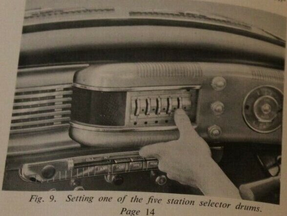
English Radio.
The peculiar and complicated control head
design comes about because of the very unusual radio fitted to the parent
version of the car designed in England. This set has no dial; just three
knobs. Instead of a variable tuning control, a five position switch selects
the required station; these having being preset by thumb wheels behind
the dash panel.
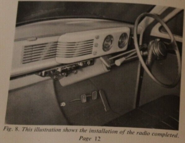
Radio installation for the English made car.
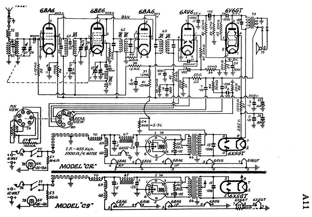
The design is a completely conventional
six valve superhet. Superhet theory has been covered elsewhere so won't
be repeated here.
Points to note; unlike the later RL/RM,
the CR/CS does have delayed AVC. A slight negative voltage of -2.3V, obtained
from the power transformer centre tap, prevents the AVC rectifying diode
(pin 5 of the 6AV6), conducting until the signal strength reaches a certain
level.
This is a standard arrangement in better
quality receivers, and prevents the gain of the receiver being unnecessarily
reduced by noise. Once the signal is strong enough, then the gain
is reduced.
As with the RL/RM, the 6BA6 IF amplifier
is run at reduced gain, no doubt to retain stability, but it also has no
AVC applied. Only the RF amplifier and mixer have AVC applied. This is
an unusual arrangement, and it is not clear why Astor did this.
Also, like the RL/RM original circuit,
the volume control pot is connected directly across the detector load resistor
without an isolating capacitor. This is odd, because with the pot as a
DC load, the load resistor (38) is unnecessary. Having said that, the best
choice is with a separate load resistor, but capacitively isolated from
the volume pot. DC through the volume control pot is undesirable since
it creates noise when the control is adjusted.
The circuit shows a 6V6 output valve, but
the set being restored had a 6AQ5. This is of course electrically equivalent,
so the circuit remains the same - just the socket is changed.
Like most valve car radio models of the
era, there are both 6 and 12V versions. Astor designates this by changing
the second letter of their two letter model numbers. AWA changed the third
digit of their model numbers. Not only was there a prevalence of English
12V cars, but by the mid 50's, American cars were changing from 6 to 12V.
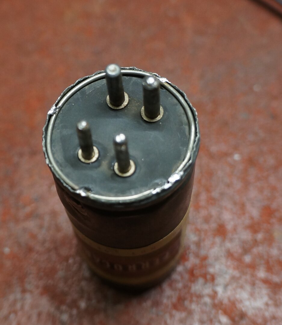
The difference between 6 and 12V models is the wiring of the heater circuit, into a series-parallel configuration for 12V. Some sets, particularly those of AWA manufacture, simply substituted the 12V heater equivalents of the valves. The vibrator and vibrator transformer are also replaced with 12V types. As with other 1950's Astor car radios, their own branded Ferrocart vibrators are used; PM237 for 6V, and PM238 for 12V.
Note that the timing (buffer) capacitor (15) is shown on the circuit as 0.004uF. In the examples seen to date, this has actually been 0.0082uF. When restoring one of these sets, it is very important to check this, because with inadequate timing capacitance, the vibrator will have a short life. Even so, it's always important to check the waveform on a CRO just to be sure.The dial lamp circuits are merely representative, and vary depending on the particular control head.
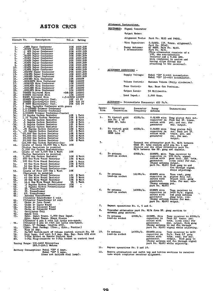
Detailed parts list and alignment instructions.
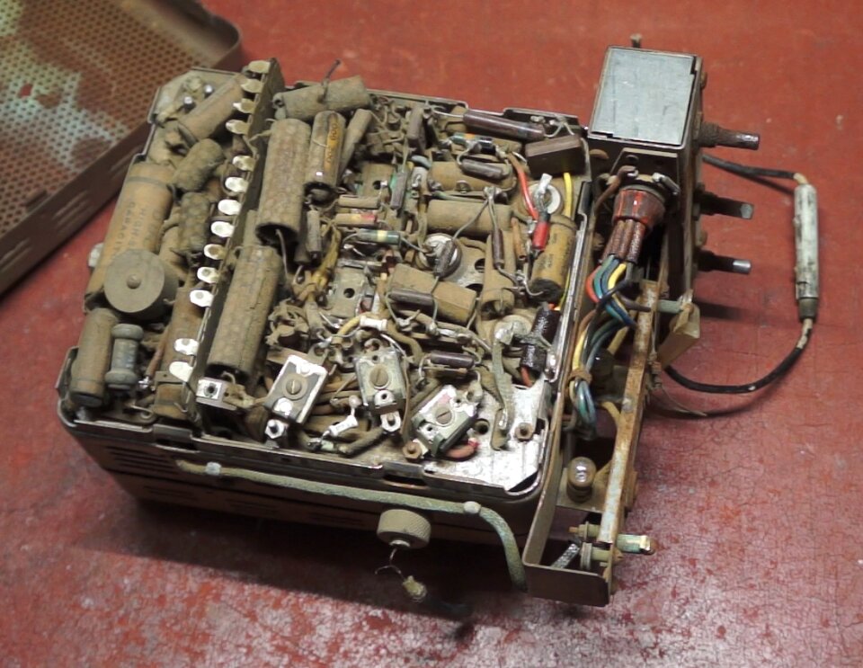
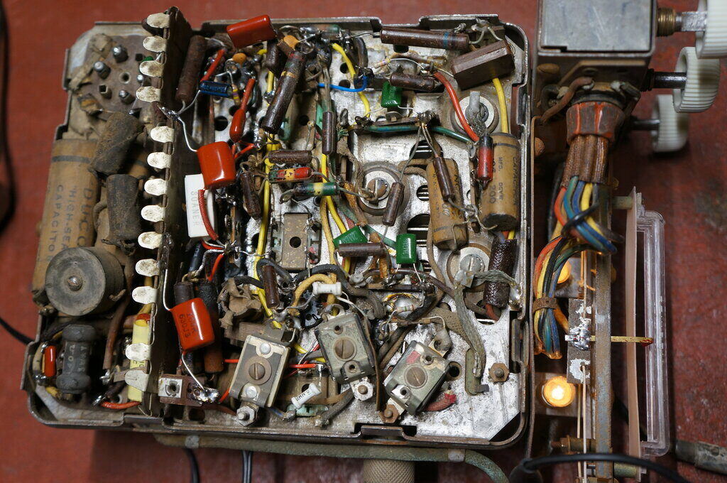
The dusty upwards facing side.
Getting the covers off these sets is usually
a matter of just twisting a screwdriver in the spring clips which hold
them on. With the Vauxhall version, the bottom mounting bracket has to
be removed first, to get to the side with the valves, vibrator, and other
chassis mounted parts. There's a nut on the back of the radio, and then
two screws behind the dial which have to be removed. It's important not
to remove all four screws here, unless you want the control head coming
off too.
Inside was exactly as expected - an original
array of IRC resistors and paper condensers. All were covered in dust,
since for the Vauxhall, the radio is mounted with the components on the
top side.
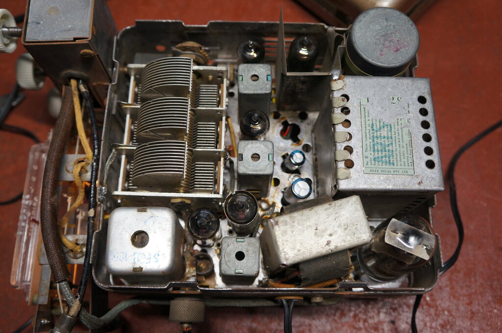
On the other side were the usual valves,
vibrator, transformers, and the three gang tuning condenser. The rubber
coupling for that looked reasonable, but was in fact quite brittle and
would have to be replaced.
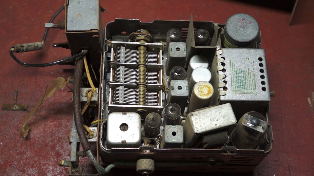
All clean here since this is the downward facing side.
Again, the rubber wiring had gone brittle
and was largely in need of replacement.
The aerial socket is a screw on type which
resembles a microphone connector, but the centre contact is recessed slightly.
Conveniently, the aerial plug was attached, with a short piece of coaxial
cable remnant remaining. This meant I could make up an adaptor to take
a modern aerial with Motorola plug, rather than replace the socket as I
did with the RM.
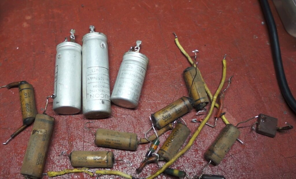
All the electrolytics were replaced as well as the paper condensers.
Most of the resistors tested OK, but some
of the high value ones needed replacing, as expected. The micas in the
high voltage positions (20) and (27) were replaced with ceramics, since
silver migration is now a problem, and causes intermittent
scratching sounds in the audio.
The vibrator timing capacitor (15) was
replaced with a 2kV MKP polypropylene type.
One look at the condition of the rubber seals of some of the electrolytic capacitors was enough to warrant replacing them. One measured open circuit on the ESR meter. Given their condition, it was best to remove them from circuit, rather than just parallel new ones across them. After extracting them from the chassis - with a Scope iron to get the necessary heat, a three lug tagstrip was installed to mount the new ones, since they were of the PCB mount type.
Tuning Drive.
Like the RM, the rubber coupling between
the control head and the gearbox for the tuning condenser had to be rebuilt.
The replacement is made from a 16mm diameter chair tip and turned down
on a lathe, as described in the RM article.
To replace it required lifting out the
tuning condenser, and this required disconnecting several wires. Some of
these are braided earth connections and require a Scope iron to get enough
heat. The anti backlash gears were a bit worn and needed resetting.
Control Head and Dial.
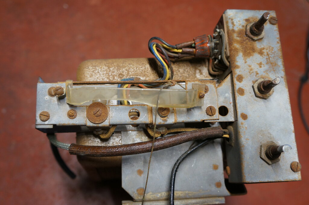
Tone control at right was seized up.
The ability to detach the control head
from the radio makes repairing it much easier. The remaining two screws
are undone, and the seven pin valve socket unplugged. All that remains
is the 12V feed into the radio from the switch in the control head, and
this is desoldered under the cambric tubing where it is joined. Except,
in this case it just fell apart. The assembler didn't use enough solder.
First thing was to clean the rust off
the control shafts with emery paper and a knife. It had been noted that
the tone control was seized up, and even with pliers it wasn't coming free.
CRC left to soak down the shaft overnight didn't free it up.
Obviously, it would have to be dismantled.
In fact, some force with a pin punch was
required to get it out, once the back was off the pot. Surprisingly, it
was a wirewound pot. This is unusual for a value so high (100k). Once the
shaft was out, it was cleaned up and fitted freely.
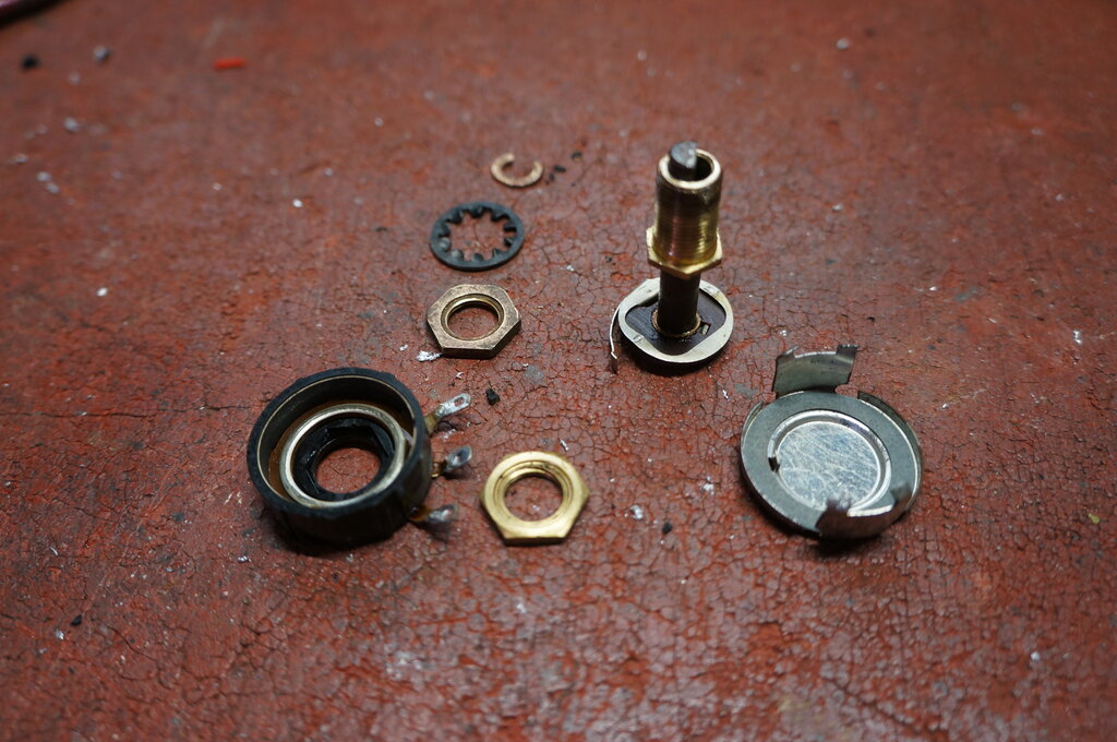
Dismantled tone control.
Dial.
Probably more work went into this than
the rest of the set. The dial lens is the same as the FX and FJ Holden
sets made by Astor. I found two sources on the internet; one much cheaper
than the other. It appeared the cheaper one was actually the manufacturer,
and the other supplier was adding their own profit. Unfortunately, the
first supplier did not respond to my query, and I thought it might be an
old ghost site. So, the knobs and dial were ordered from the second site.
Unfortunately, this supplier required knobs to be bought in pairs; not
singularly - so for three knobs, one is left over. Given how expensive
they are, this is not desirable. As it happened, about six weeks later,
the first (manufacturer) site did reply, but it was too late - and they
did offer the knobs individually!
The dial on offer is physically the same
as the original, and an extremely good reproduction. However, the dial
is labelled with "Airchief" and a 0-10 scale, rather than the station call
signs. This seems to be the earlier type as used on FX Holdens. By the
FJ came along, the dial lens had no labelling, but slip in call station
labels for each state. This is what was used in the Vauxhall. We can't
be too picky, and the 0-10 dial is all that is available. Only an absolute
purist would pick the difference.
Importantly, the dial fits perfectly,
and looks good.
First dial job was to clean up the dial
cord guides (there's no pulleys), and replace the dial cord. The original
dial cord spring was present and was re-used. Next, the new dial lens was
mounted. In the past there was some kind of plastic screen so the dial
lamp filaments and guts of the mechanism were not visible through the lens.
This was all gone except for a tiny bit under one of the screws. It looked
like cream coloured plastic. What to use to replace it with? We needed
a light coloured plastic which was translucent. I found the perfect thing
in the plastic bottom of a take away food container. This part of the container
had a kind of frosted appearance which was exactly what I was after.
Cut out and installed behind the lens,
it looked perfect, with ample light shining through.
New knobs and dial transform the appearance.
Finally, was the dial pointer. The original was so badly damaged that I made a new one with a strip of brass painted red and bent to shape. This was soldered to the original part that attaches to the dial cord.
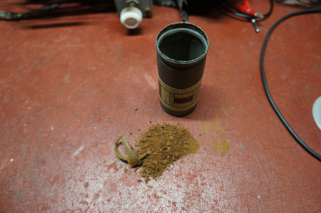
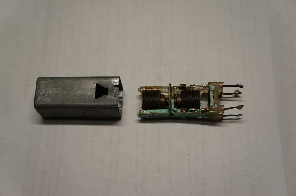
Foam rubber can lining now powder.
The can crimping came apart without much
disfigurement, and all was revealed. The foam rubber can lining had solidified
and turned to powder. With that getting caught in the mechanism, it was
no wonder operation was erratic. New foam rubber lining was installed.
As for the vibrator itself, while it did
start reliably, the duty cycle was less than it should be. Less than normal
duty cycle means a lower B+ voltage, as well as the timing circuit not
working correctly.
As with the RM vibrator, I cleaned the
contacts with 600 grade sandpaper, and re-gapped the contacts by adjusting
the thickness of the mica washers. This is the second Ferrocart vibrator
I've adjusted this way, and it is definitely the way to go, rather than
bending contacts.
I suspect this is how it was done in the
factory.
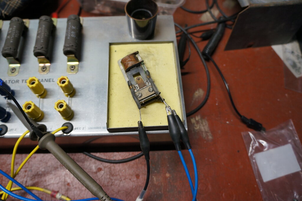
Testing the vibrator on the test panel.
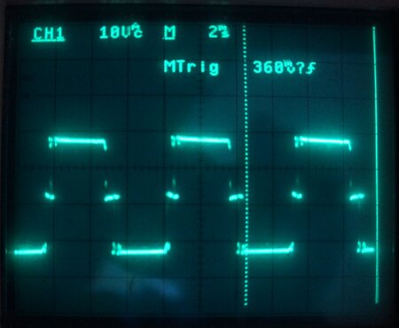
Duty cycle restored to about 80%.
With the vibrator reconnected to the set, the waveform was checked across the transformer primary and found to be correct.
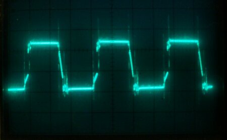
Primary waveform. Some slight asymmetry is visible, but not enough
to worry about.
Because the zinc can was in good condition after being opened, I tried a new method of re-securing the mechanism inside. A piece of tinned copper wire was formed around the outside of the can, then with the mechanism back inside, it was soldered at four points around the lip inside the can bottom.
Mechanism can easily be removed without further damaging the can.
I could have rolled the can lip with a
brass roller I made for the purpose, but it looked pretty good as it was.
At this point, the radio was now working
well - except for one thing!
Inside the IF transformer.
I couldn't fault it. Even with a signal
generator connected to its primary pins, moving them about did not change
the signal output from the secondary. I did this test in case there was
a faulty mica tuning capacitor in the base. Back in the set, and the fault
was still there.
This was getting quite bizarre after my
next step, which was to bypass the transformer altogether. All four wires
were disconnected from the IFT, and the primary circuit completed with
a 10mH choke. A 68pF condenser connected the plate connection to the grid
of the IF amplifier (there was already a 500k to complete the grid circuit).
Aside from broader tuning, this substitute actually worked very well.
Would you believe, that with all pins
disconnected, that pushing on them still caused the signal to come and
go? Almost surreal, I started to wonder if it was the actual movement of
the IFT can itself. Turning over the radio and looking at the can - there
it was.
Yours truly had forgotten to resolder
one of the tuning condenser's earth braids. It was resting against the
side of the IFT such that if the IFT moved, the braid would touch against
the fixed plate connection on the tuning condenser for the RF stage input.
Out with the soldering iron and fixed
instantly!
Capacitors and resistors replaced.
Note new electrolytics in front of the vibrator transformer. Third
one was mounted on the other side.
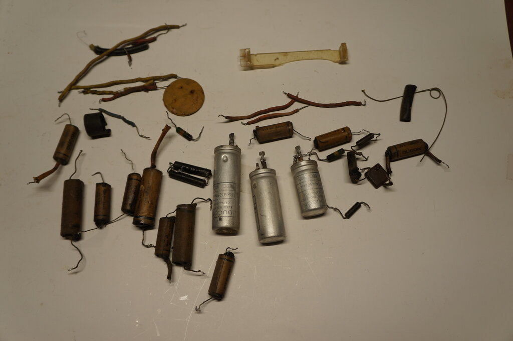
Components replaced.
The radio was also taken into the backyard and operated from a battery, away from all the RFI in the house. Performance was excellent. 2LT came in like a Sydney station. Even though the distance is about the same, 2LT has a directional transmitter, with the signal aimed away from my location.