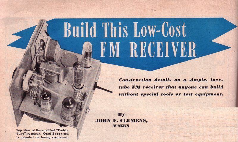
Back in the 1990's I attempted this project as described here. It was originally presented in the August 1951 issue of Radio News. (This can be viewed at www.americanradiohistory.com). One of the things that attracted me to the project, apart from the Fremodyne circuit, was the compact design mounted in a small steel box. With my original attempt, I had to make a fairly extensive change to the operating conditions of the super-regenerative detector, to get the circuit usable. This had me curious given the major change that was required.
Fast forward to 2017, and I was sufficiently intrigued to try the project again, but this time a far more faithful replica of the original - in the cute little box too! And, I would find out what the problem was with the original circuit. This time round, I was going to use the series heater circuit and original valves, and simply run it as I would any other U.S. appliance, from a step down transformer. Running from a double wound transformer also eliminates any shock hazard. My first attempt at this receiver was in the days before I had the internet and before ebay even existed. As a result series heater valves were rather obscure in Australia. These days of course, there is no problem buying series heater valves. My valve collection had increased considerably in size since then, anyway, and I now had suitable valves.
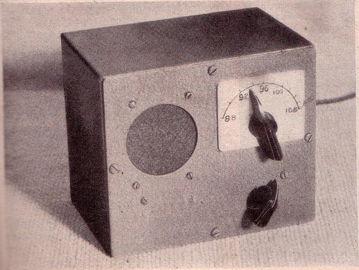
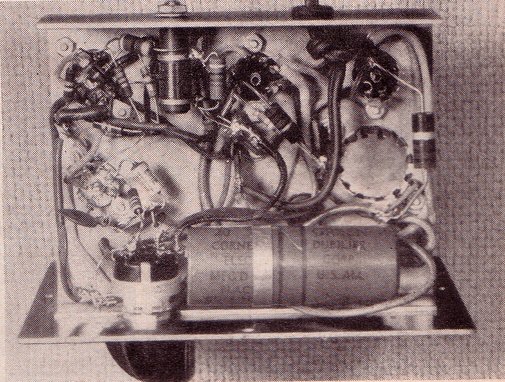
Front and under chassis views of the project as presented in Radio
News.
The Design.
As originally presented, the set was built
in a 6" x 5" x 4" metal box. An AC/DC series heater power supply was used,
but with an isolated negative busbar so the metal chassis would not be
live. A 2" x 3" oval speaker provided the sound.
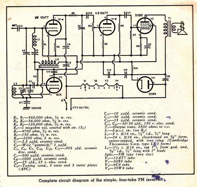
Circuit as presented in Radio News.
The concept of the design was to simplify
the original Hazeltine Fremodyne circuit to the minimum workable circuit,
and provide a power supply and audio amplifier, all in the self contained
box. For those not familiar with the Fremodyne, there are articles elsewhere
on this site, but in particular, this
one gives a very detailed explanation.
Briefly, the Fremodyne is a super-regenerative
superhet optimised for the 88-108Mc/s FM band. The circuit uses a twin
triode of the 12AT7 or 14F8 type. One triode is the local oscillator operating
21.75Mc/s above or below the received frequency, and the other triode is
a super-regenerative detector operating at the 21.75Mc/s IF. The detector
is stabilised so that over a variation of supply voltages and component
tolerances, there is no need for regeneration adjustment. Audio output
is sufficient to drive a triode-pentode audio amplifier.
Of course, as a super-regenerative detector
is for AM reception, it is necessary to tune slightly off carrier so that
the FM signal is converted to AM. This occurs because of the selectivity
curve of the detector's tuned circuit.
The Radio News project works on the same
principles. However, the aerial input is not tuned; only the local oscillator
is. This means only a single gang tuning condenser is required.
The local oscillator circuit is largely
unchanged from the original, except that Hazeltine used a cathode choke
instead of a tapping on the oscillator coil, for feedback. Some commercial
manufacturers did likewise.
The major difference is with the detector circuit. It has been simplified at the expense of the stabilising components. Also, to eliminate a capacitor, the IF coil is now tapped and placed in the cathode circuit. Audio output is taken from the plate load rather than the cathode circuit.
While the circuit works, it would be unsuitable for commercial production. With the local oscillator operating on the low side, there is no image rejection, and some stations can be received at two points on the dial. This would obviously be confusing for a non technical user. Also, for optimum detector operation it is likely that some components would have to be selected on test for individual sets, and if the detector valve is replaced, these again may have to be changed.
How the circuit works.
Starting with the detector, like any super-regenerative
detector, this stage is actually an oscillator operating at the received
frequency. Here, a 12AT7 triode is used. In this case the detector operates
at a fixed IF of 21.75Mc/s. As well as oscillating at this frequency, it
is taken in and out of oscillation at a supersonic rate - known as the
"quench" frequency. The oscillation in this receiver occurs by the tapping
on the coil in the cathode circuit. An out of phase voltage appears at
the non-earthed end of the coil winding which is fed into the plate circuit,
causing positive feedback. The frequency is determined by the 15pF and
coil inductance. The quench is produced thus: As grid current flows, the
.005 grid capacitor (C3) charges and eventually the grid becomes sufficiently
negative to cut the triode off, stopping oscillation. The capacitor discharges
through the 560K (R1) and the cycle commences again, but at a supersonic
frequency so that it is not heard by the listener. Quench frequency is
also determined by the grid voltage and amount of feedback, so it is also
dependent on the plate resistor 56K (R2), and feedback capacitor 500pF
(C4).
The 6C4 is connected as a Hartley oscillator
operating at 21.75Mc/s below the signal to be received. A low value "gimmick
capacitor" (an insulated piece of wire placed next to the oscillator coil)
couples the local oscillator signal into the grid of the 12AT7, along with
the off air FM signal. Because of non linearities in the detector response,
the two signals mix in the conventional way. This results in the incoming
VHF FM signal being converted to a fixed 21.75Mc/s IF.
The incoming VHF signal is fed into the
mixer via a 2.5pF condenser and a broadly tuned aerial coil. This is tuned
by stray capacitance to the centre of the FM band; about 100Mc/s.
Because the super-regenerative detector
is AM, it is necessary to tune to the side of the response curve so that
slope detection can take place, and FM signals can then be detected.
Detected audio, superimposed on the quench
waveform, appears at the 12AT7 triode plate. As the quench frequency is
higher than that of the highest audio signal received, a simple low pass
filter comprising of the 120K (R3) and .001uF (C5) reduces this, leaving
mostly just the audio signal.
This is coupled to the 1M volume control
via a .005uF (C6) DC blocking capacitor.
From here, the audio is amplified by a
conventional triode-pentode circuit, using the remaining 12AT7 triode and
a 50B5 power pentode, which drives the speaker. Because the 12AT7 has high
gain, the designer felt that a cathode bypass capacitor was not required.
Thus, the cathode bias resistor 4.7K (R5) is not bypassed. The output from
the 12AT7 is then fed to the 50B5 in the normal way, via a blocking capacitor,
.005uF (C7), and grid resistor 560K (R7). Cathode bias is used for the
50B5, comprising of the 150R (R8) and 25uF (C8).
To fit in with the design concept of simplicity,
where possible, the number of different resistor and capacitor values has
been minimised; hence the prolific use of .005uF condensers. Likewise,
resistor values have been kept to a few different types.
The power supply is a conventional AC/DC type, with B+ coming from the half wave rectified 117V mains, and the valve heaters are all 150mA types, connected in series across the mains. The B- connections in the receiver are all made to an isolated busbar, which allows a metal cabinet to be used without being a shock hazard.
Building the new receiver.
First thing was to source the metal box.
Surprisingly, a box of the same dimensions was still available from Farnell,
but by the time I would have had it in my hot little hands, the cost was
up around $30. Considering I had all the metal work tools necessary to
make my own, I thought that was too much. So, that's what I did. I made
up the box out of light gauge steel sheet. This is stronger than aluminium
for the same thickness. Given that there would be about 25W dissipation
from the circuit, I punched three louvres at the back. The chassis was
then punched and bent. It is secured to the front panel by the volume control
and two of the speaker bolts. The original Radio News set was finished
in blue wrinkle paint. I didn't have that so used green hammertone.
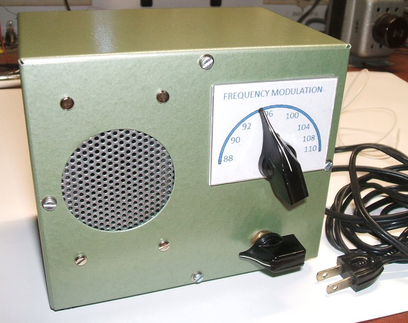
New receiver is a close replica of the original Radio News project.
The next thing was the dial. Originally, this was an aluminium plate with the frequencies engraved into it. That was a little crude for my liking, so I decided to make up a printed paper label with a piece of Lexan to cover it. However, before the dial could be designed, the local oscillator needed to be built up and tested so that the frequency positions would be known.
Local Oscillator.
Here I was forced to make the first departure
of the design. While I did have the specified variable condenser, it was
in poor mechanical condition, and was frustrating to try to get it working
reliably. I did have however, a much better quality one, but alas of only
10pF maximum capacitance. This would be insufficient to tune across the
band.
But then I realised, if I ran the local
oscillator on the high side, the capacitance for the tuning range would
be much less than when run on the low side.
Indeed this turned out to be the case
and there was more than sufficient tuning range. This can be illustrated
as follows:
For a low side oscillator, the frequency
range has to be (88 - 21.75) to (108 - 21.75) which is 66.25 to 86.25.
It has to tune across 20Mc/s.
When the oscillator is on the high side,
the range is now (88 + 21.75) to (108 + 21.75) which is 109.75 to 129.75.
This is also of course a 20Mc/s tuning range. The difference however, is
in the inductance to capacitance ratio. For a given inductance, much less
capacitance is now required to tune the same frequency range.
I was not happy about the long lead lengths between the 6C4 and the tuning condenser/oscillator coil, but surprisingly it worked perfectly, and there was no problem getting strong oscillation. My concerns were exacerbated because of the inability to earth anything directly to the chassis. The negative busbar is connected to the chassis in terms of RF by means of a .0047uF ceramic condenser. Sensibly, this is mounted right at the tuning condenser where it will be the most effective. If it was located elsewhere, the tuning condenser shaft would be live at RF and tuning would be affected by hand capacitance. As it turned out, there was no problem with hand capacitance, which if anything, would be more obvious at the higher frequency.
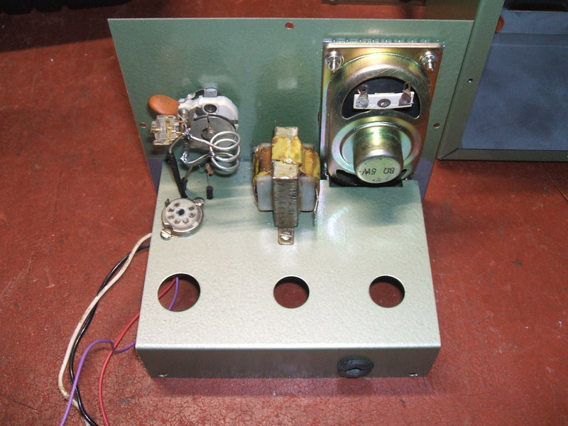
Testing the local oscillator. Looks just like the original but now
runs on the high side. The ceramic isolating condenser (C17) can
be seen at the left of the tuning condenser. The speaker fitted at the
time this photo was taken was found to be faulty.
Now it was time to create a dial scale. I used Paint in XP to draw an arc, and Irfanview to insert the text. Covered with a piece of Lexan, it looks quite professional for a home made dial.
50EH5 audio output.
The original article specifies a 50B5
valve for the audio output. I could have easily bought a few off ebay,
but it happened that I had a quantity of 50EH5's. These are the same physically,
use the same 7 pin socket, but are about twice as sensitive. Apart from
a change to some pin connections, and the value of the cathode resistor,
there would be no obvious departure from the original.
The rest of the construction could now begin. I decided to install the power supply and audio circuits first, and make sure they were all working before dealing with the super-regenerative detector. I was still anticipating some experimentation would be required.
Power Supply.
In the original design there is an obvious
design fault with the power supply. The heater voltages add up to 104V
but there is no dropper resistor for the specified 117V supply. That is
not good for valve life in the long term. The ideal dropper resistor in
theory is 107 ohms, which unfortunately is not a preferred value. 120 ohms
was tried but the heater voltages were just a little low. With 100 ohms,
the voltages were much closer to what they should be. Resistor dissipation
is just over 3W, so a 5W resistor was used. Including the resistor also
has the benefit of reducing the switch on surge when the valve heaters
are cold.
The next design fault was that there was
no resistance in series with the 35W4 plate. This is required to limit
the peak plate current due to the first filter capacitor charging. The
data says 15 ohms is the minimum, but I used 22 ohms for greater protection.
This resistor will also act as a fuse if there is a B+ overload.
The 35W4 has a tapping on its heater for
a dial lamp, but this is not used with this receiver.
Isolated Busbar.
As mentioned previously, the negative
connections are not made to the chassis, but rather to an isolated busbar
which runs around the the chassis. I ran the busbar between the centre
shields of each valve socket. Such a scheme has to be designed carefully,
because in reality the "earth" provided is not as good as that made directly
to the chassis. That's because the busbar is bypassed at only one point,
which is going to be far away from certain parts of the circuit, in terms
of RF. The bypass capacitor can only be a limited value before its reactance
is too low and the possibility of getting a shock becomes likely.
The aerial connection is already isolated
by the aerial coupling capacitor so no shock hazard exists there. Even
if this capacitor broke down, there is still no direct connection to the
mains, unless of course the 12AT7 detector triode suffered a grid to cathode
short.
The loudspeaker is isolated by the speaker
transformer. The transformer I used is actually rated for mains isolation;
originally from a live chassis TV set.
Conveniently, the switch pot for the volume
control I had was a double pole type, so that the mains is completely disconnected
when the receiver is off.
The single pole switch used in the original
design can leave the receiver circuitry live even when the switch is off.
Once wired up, the power supply and audio
sections worked as they should, with no instability or hum problems. It
looked like the isolated busbar was successful.
Rear view with back removed.
The IF coil.
Of course, there was no hope in obtaining
the specified coil former for the IF coil. In my previous version of this
receiver, I simply used the former from an AWA TV set sound IF coil.
This time, I wanted to try something closer
to the original, to see if this was the cause of the problem I had then,
which was a very low IF, and very audible quench frequency.
Looking through my parts collection, I
did find a likely looking former of about the right diameter, and conveniently
with about the right number of turns already on it, including the centre
tap. I had vague ideas I had wound up this coil many years ago for something,
but can't remember what. The core material was unknown.
All the wiring was done for the detector,
including the broadly tuned input circuit. This is mounted on the top side
of the chassis, and the aerial connects to it via a 2.5pF condenser (I
used 2pf). The IF coil was temporarily connected into the circuit, and
the receiver switched on.
Much to my surprise, stations were at
once receivable, and the sensitivity with no aerial was quite good. The
quench was low, at 17kc/s, and only just audible. The real problem of course
was when tuned to a station, there was a 2kc/s beat with the stereo subcarrier.
In 1951 when this project was designed, that was not a problem as stereo
transmissions did not exist, and assuming the designer, John Clemens was
middle age or older, the 17kc/s quench would probably not have been audible.
Contrary to my comments concerning my
previous attempt, the circuit does actually work with the greater number
of coil turns, and the components specified. This confirmed that the core
material was of utmost importance.
The Final Circuit.
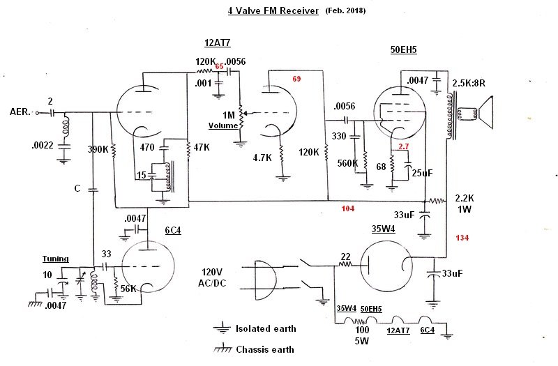
It is easier to follow circuit operation with this redrawn diagram.
Slight changes were required but the circuit remains schematically almost
the same as the original. C16 (.0047uf) was connected between the 35W4
plate and cathode after this circuit was drawn.
In the modern day, it is of course essential that the receiver is compatible with stereo transmissions. This means increasing the quench frequency so that the beat between it and the 19kc/s pilot tone is inaudible. The main components that affect this is the grid circuit time constant consisting of R1 (560K) and C1 (.005uF) [see original circuit]. The feedback condenser C4 (500pF), also has significant effect. While it was certainly possible to increase the quench frequency sufficiently, the sensitivity dropped off considerably.
As an experiment, I tried using the component values as per my previous attempt. That receiver worked very well with a 50kc/s quench frequency and the ferrite cored IF coil I used then. Perhaps not surprisingly, it didn't work with the new coil at all. Of course, I could ultimately use a ferrite core and modify the circuit as I did before, but the challenge was to see how I could get the original specified coil to work with adequate sensitivity. In situations like this, a spectrum analyser is extremely useful. One can see how optimum the behaviour of a super-regenerative detector is.
Another thing becoming evident was that the output of the 6C4 local oscillator is quite strong, so much that the grid of the mixer valve can be driven to cut off. The problem here is that for maximum sensitivity, the super-regenerative detector has to oscillate fairly weakly, and with too much L.O. injection it stops oscillating altogether. Aerial loading also affects operation, despite the circuit being a superhet. It can be seen the local oscillator signal is injected into the same place as the aerial is connected, hence aerial loading can affect the amount of L.O. injection..
The speaker I had used turned out to have a problem with its voice coil. Distortion was obvious at low volume, which was suggestive of the voice coil rubbing against the magnet, but it did not improve as the cone was pressed in different directions. It could be the coil winding was actually loose. Rather disappointing since it was a new speaker. It was easier just to replace the speaker than attempt to repair it.
Detector component values altered.
Quite some experimentation was required
with component values to get good performance, and with sufficient amplitude
of oscillation in the super-regenerative detector so that the local oscillator
injection did not cut it off.
Suffice to say, reducing the original
56K plate load (R2) to 47K ensured strong oscillation. The quench frequency
was raised to around 30Kc/s by reducing the 560K grid resistor (R1) to
390K, and the .005 (C3) to .0022uF.
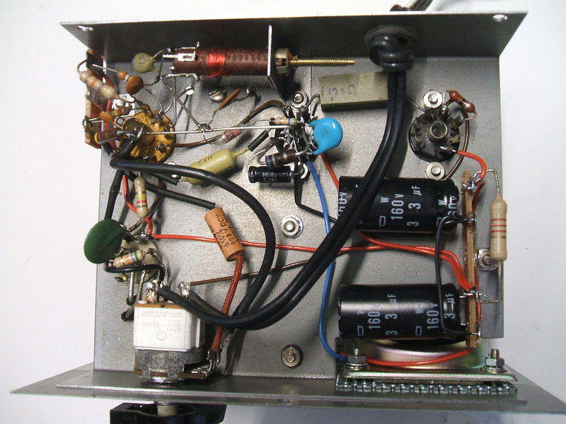
Under the chassis of the new receiver.
It is important to note that a super-regenerative detector's operating conditions are critical for highest sensitivity. While it is a simple matter to make an oscillating detector go in and out of oscillation at the required rate, if the quench waveform is not optimum, and if the oscillation amplitude is too high, then sensitivity suffers. Unfortunately, many published super-regenerative circuits are very poor performers because these details have been overlooked. There is a lot more to it than merely obtaining a rushing sound - that gives no indication as to sensitivity, contrary to popular opinion.
By the end of my experimentation, the performance
I obtained is as good as it can be, keeping with the original circuit configuration,
but with changed component values.
It was tempting to simply convert the
super-regenerative detector to the official Fremodyne circuit, with the
advantages of stabilisation and an optimised quench waveform, but that
would be negating the whole point of this project, and it's not as if I'm
short of "real" Fremodynes!
Nevertheless, the new receiver certainly
works and is practical to use. Strong stations 100km away can be received
with no aerial, although with some noise.
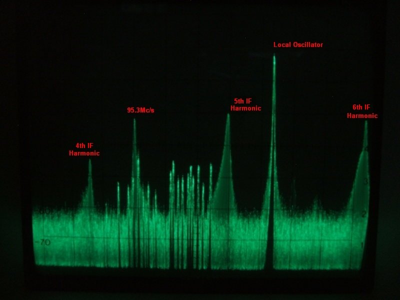
Spectrum analyser shows the detector harmonics at 87Mc/s, 108.75Mc/s,
and 130.5Mc/s. Station received is at 95.3Mc/s. Local oscillator is at
117.05Mc/s. Although the detector is working at a fixed 21.75Mc/s, it also
radiates at the station frequency, due to superhet action.
Quench filtering inadequate.
Quench filtering of the original circuit
was once again found to be inadequate, despite the quench frequency being
almost doubled. This was improved by adding a .0047uf plate bypass for
the 50EH5 and also a 330pF grid bypass. When quench filtering is insufficient,
the audio stage is overloaded before full volume is reached. The effect
is that the volume actually decreases once the volume control is turned
past a certain point.
Aerial.
The original article states that "two
or three feet of wire" can be used for the aerial. It was mentioned that
one side of the power line could be used with "practically the same results".
While the idea of a power line aerial would be convenient (and for strong
signals does work well), chokes would need to be installed in each side
of the power cable just before the on/off switch, for it to work properly.
Not doing so would reduce the effectiveness when you consider that one
side of the mains connects to the receiver's "earth". I simply took the
wire aerial option, using a 75cm (quarter wavelength) length of wire. This
fits in with the receiver's simplicity and portability. I felt it pointless
to install a coaxial aerial socket as it would mean being tethered to an
outdoor aerial, or a separate indoor aerial. And again, it would be a further
departure from the original design.
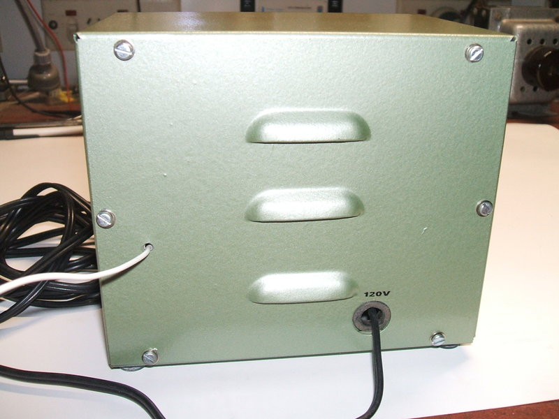
Back of receiver shows ventilation louvres, aerial, and mains input.
Performance.
The small loudspeaker does detract from
sound quality, but this is a trade off with the compact construction. In
any case, the sound is not hi-fi, although depending on the reception conditions,
can be quite good. No tuning drift is evident.
As a matter of curiosity, I did try the
receiver on 120V DC. It does work, although the B+ at the 35W4 cathode
is down to 112V, and the secondary B+ rail is now 88V. This is expected
of course, because there is not the 170V peak present as there is on a
120V AC rms sine wave supply. Operating on DC, total consumption is 185mA.
It is important to note that if this receiver was to be used normally on
a DC supply, the power switch must be suitable for DC operation. This is
because an arc will occur when the switch is turned off. On AC the arc
extinguishes as the waveform goes through the zero volt point.
Sensitivity is adequate with stations
receivable with no aerial connected. The following measurements were taken
to give an idea of sensitivity:
| Frequency (Mc/s) | Discernible | Entertainment Quality | Noise Free |
| 89 | 5uV | 10uV | 300uV |
| 99 | 63uV | 200uV | 450uV |
| 107 | 14uV | 120uV | 315uV |
These figures are very vague and subjective,
but give a useful indication of what to expect. Interestingly, there is
a drop off in sensitivity around the middle of the band. The signal generator
used for the test is a Rhode & Schwarz SMS. 50Kc/s deviation was used
for the FM signal.
Due to the inefficiency of slope detection,
sensitivity is somewhat better with an AM signal. The problem with slope
detection is that the receiver cannot be tuned to the centre of the
response curve, where the receiver is most sensitive.
Initially, I had omitted C16 connected between the plate and cathode of the 35W4, because during development I hadn't found it necessary. Once the receiver was put into normal use, I did find modulation hum evident on some stations and with the aerial in certain positions. It was particularly bad with the receiver running off an inverter. Evidentally, C16 was necessary, and installing it fixed the problem.
There is no doubt the receiver achieved
what it set out to do. In an era when components were more expensive than
now, the simplification of the Fremodyne circuit could be perhaps justified.
However, when all things are considered, the original Hazeltine circuit
is a better performer.
Would I build this receiver again? The
answer is not in its present form. Certainly, the compact metal box construction
is elegant, as is the AC/DC power supply. If I was to build another, it
would use my own 12AT7 design (used in several projects described elsewhere
on this site) which has far superior sensitivity to both this circuit and
the original Hazeltine Fremodyne circuit. It could be done with the same
valves, in which case the 12AT7 would be the RF amplifier and detector,
and the 6C4 would become the first audio amplifier.
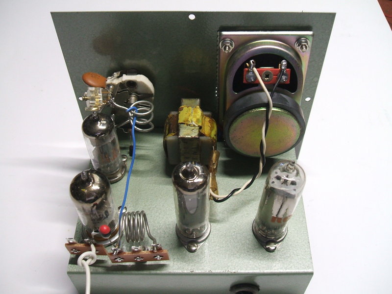
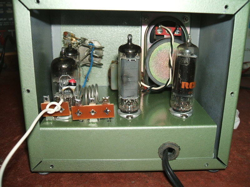
Above chassis view, with new speaker installed. The local oscillator
coupling can be seen - it's the blue wire. Also the aerial connection and
2pF coupling condenser are visible next to the aerial coil.
Summary of changes.
The receiver does "work" when built exactly
as original, but sound quality is poor, and valve life would be shortened.
The changes made were: