This receiver was described
in Radio News, August 1951, by John F. Clemens, W9ERN. Apparently, Mr Clemens
thought he'd see how the Hazeltine Fremodyne circuit could be simplified
without a reduction in performance. The result was a rather cute looking
FM reciever constructed in a small steel box. During the mid 1990's I decided
to try out the modified circuit, and found not all was as the article described.
If you have not already read the Fremodyne
article, I suggest you do so at this point to understand the unique design.
It will help you understand how this design departs from the original Hazeltine
concept.
The simplification involved removing a
number of parts associated with the quench waveform control and stabilising
circuits, the three RFC's and using an untuned RF stage, thus requiring
only a single gang tuning condenser. The super-regenerative IF stage was
changed to a Hartley type oscillator.
Circuit Operation.
Looking at the circuit we can see a resemblance
to the original Fremodyne. Firstly, the local oscillator is using a 6C4,
which is equivalent to one 12AU7 triode. To eliminate the cathode RFC,
the oscillator has a cathode tap on the coil. Unlike the Fremodyne, the
oscillator runs on the low side. The aerial coil is broadly tuned to the
centre of the band and left at that, eliminating an extra tuning gang,
and the hassles of tracking alignment.
The received signal is fed into the following
super-regenerative IF stage, along with the local oscillator signal, and
as in the original circuit, the two are mixed to produce the IF at 21.75Mc/s.
In the modified design, the super-regenerator is nothing fancy at all;
just a simple self quenching circuit. Quench frequency is dependant on
the 500pF (C4) the 560K (R1), and the .005uF (C3).
Most of the simplification in this circuit
has been done by eliminating the automatic stabilising circuits which exist
in the original Hazeltine Fremodyne circuit. This may mean that the simplified
circuit is more susceptible to mains voltage variations and the actual
components, and layout, used to build the circuit. As no regeneration control
has been provided, it may be necessary to optimise certain component values
to get the best performance. The fact that the super-regenerative detector
is operating at a fixed frequency does however mean this should be easier
than first thought.
Like my own home-made Fremodyne receiver,
this one also included a loudspeaking stage. Here, the circuit uses the
other half of the 12AT7 as an audio amp with a 50B5 output pentode.
Armed with enthusiam and curiosity,
I set about building this receiver with a few mods. Firstly, the AC/DC
power supply was not acceptable at 240V with the form of construction used.
The chassis could easily become live if C17 broke down, and it's just too
easy for a strand of wire, etc. to become lodged between a component and
the chassis, also rendering it live. This sort of dangerous design was
very common in the US where the population seems to think nothing of exposed
mains connections, or the dreadful practice of connecting headphones to
live chassis sets without any isolating transformer.
Besides, valves like 35W4 and 50B5 are
not standard in Australia. There would also be the question of operating
off 240V mains, which increases the shock hazard as well as requiring a
heat dissipating power resistor to drop the heater volts. Obviously, a
transformer power supply was the way to go.
For the audio output, I had limited B+
current, and heater current, with the small transformer I chose to use,
so used a 6AU6. I didn't require much audio power and the additional gain
of this valve would also be useful. Otherwise, I constructed the receiver
to the circuit as shown. For the tuning condenser I used a modern plastic
AM/FM gang with a 1/4" shaft attached.
Design Faults.
Note that the original circuit will result
in the valve heaters being over run. Adding up the heater voltages; 35
+ 50 + 12.6 + 6.3, we get a total of 103.9V, which is obviously less than
the specified 117V mains supply. A resistance of 107 ohms needs to
be included for 120V operation. Next fault is that the rectifier valve
feeds the first filter capacitor directly. There should be at least 15
ohms of resistance in series to limit the surge current; placed in series
with either the cathode or plate.
The strange U.S. convention of having
the power switch in the "earthy" side of the mains supply has been used
in this circuit. If the plug is inserted so the neutral is being switched,
then the chassis is not live when the switch is on, but is when it's off;
the circuit completed through the valve heaters from the live conductor.
If the live conductor is being switched, then the chassis is guaranteed
live when the set is switched on. By moving the switch to the live side
of the circuit, there is at least the preferred possibility that the earthy
side of the circuit will always be at neutral potential if the plug is
inserted the right way round.
The original circuit.
First Power Up.
Turn on time...and time to deal
with getting it to work. First thing evident was inadequate quench filtering
had been provided. A 470pF from the 6AU6 grid to earth improved that. The
IF coil was the next problem. I was sceptical when I saw that 24 turns
was required. Experience taught me that for ~22Mc/s, 12 turns should
be nearer the mark. Sure enough, it wouldn't resonate anywhere near 22Mc/s,
so I rewound with 12 turns and that one was fixed. However, to be fair,
I had used a ferrite core for the coil, rather than the iron core specified.
It's quite possible that an iron core would increase the inductance so
much that 24 turns was indeed required.
Having got this far, it was plainly obvious
that the quench frequency was way too low. It was clearly audible. I had
to reduce the 500pF (C4) to 150pF and also do a major modification in the
grid circuit. Again, it's just possible it was due to my use of a ferrite
cored IF coil with only 12 turns.
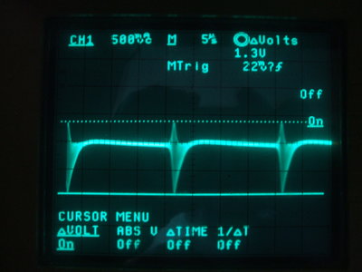
Waveform at volume control input. Quench is still quite strong.
The 560K grid resistor had to be reduced
to 27K to eliminate the quench being audible. In view of this drastic reduction
of resistance, the grid resistor needed to be fed from a voltage much lower
than the B+. Therefore I used an adjustable voltage divider to set
the optimum voltage (about 7V), so the SCA/stereo subcarrier beat could
be minimised while retaining as much sensitivity as possible. In view of
the higher quench frequency used to minimise the beat effects, I raised
the IF to 28Mc/s. The 3rd and 4th harmonics are now 84Mc/s and 112Mc/s
which are outside of the FM band. The reason for choosing a higher IF is
that there is an optimum ratio between detector oscillation frequency and
quench frequency.
Postscript: During subsequent
construction of another "Simplified Fremodyne" in early 2018, it was confirmed
that indeed the type of coil core was responsible for the vast difference
in operation. The original circuit did actually function with the components
specified, although with a rather low 17kc/s quench frequency.
Next, I found the local oscillator wouldn't
work as specified. I had to set the cathode tap at 2 turns instead of one.
This may have been because I used a bakelite socket for the 6C4 rather
than the specified ceramic type.
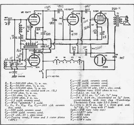
Ultimately, my version of the receiver
ended up with this circuit:
Modified circuit to use locally available parts and to allow 240V
operation.
By now the receiver was working quite well,
and a sensitivity test was performed. On AM, 5uV was receivable, but 25uV
was required for a reasonably clear signal. So, it appears to have higher
sensitivity than the original Fremodyne. I didn't test the sensitivity
on FM, but it would be less because of tuning the receiver slightly off
frequency for slope detection. Sound quality is not bad either; it does
not have that unique, slightly mushy, sound the original Fremodyne puts
out.
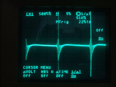
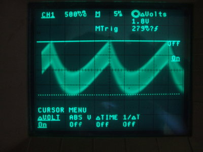
Waveforms at the 12AT7 detector cathode. Quench is 51kc/s. Waveform
was taken via a 100K isolating resistor.
What really became obvious with this receiver once I was using it, is the effect of an untuned RF input. Stations at the top end of the band ~100Mc/s were being also received at the low end of the band ~88Mc/s. This appears to be due to local oscillator harmonics. When I was using a Rohde & Schwarz SMS signal generator instead of the 6C4 local oscillator, the effect was not there. It is possible that running the 6C4 oscillator on the high side will eliminate the problem. In any case, the broadly tuned aerial coil does not seem to affect sensitivity. Incidentally, I used a GDO to tune the aerial coil to the centre of the band.
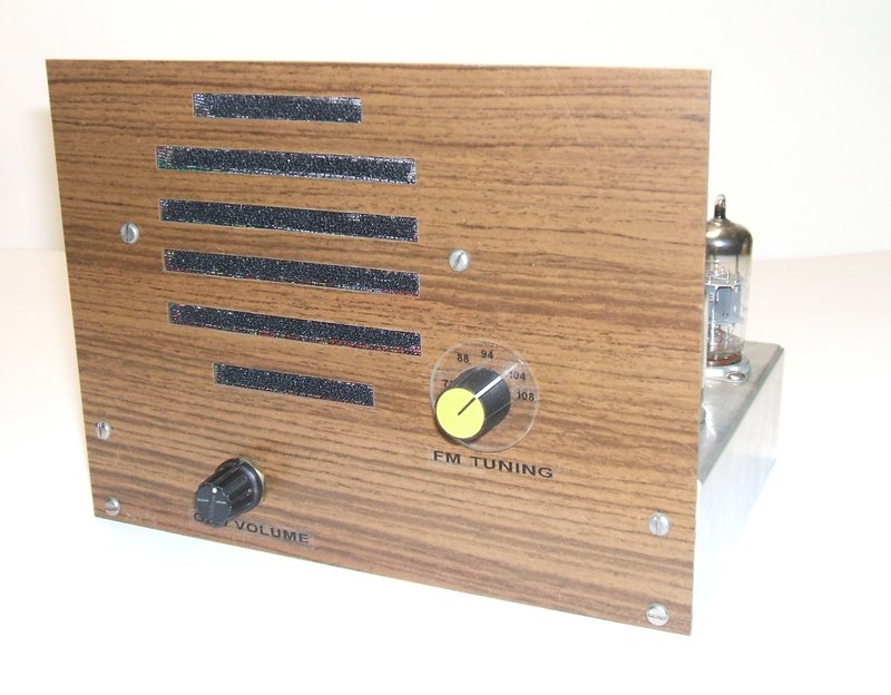
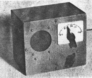
Front panel, made of Marviplate.
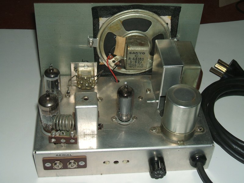
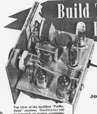
Chassis view. Layout is much the same as the Radio News design,
except of course mine has a power transformer.
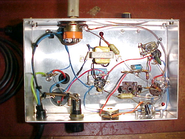
Underneath shows a very uncluttered circuit, despite the small chassis.
Conclusion:
The concept certainly works, and the receiver
is one worth building. The only possible confusion in operation is the
appearance of stations at more than one position of the tuning dial. Otherwise
it works as well as, if not better than, the original Fremodyne. It is
important to note that my comments apply to the receiver as I modified
it, and I cannot comment on the original.