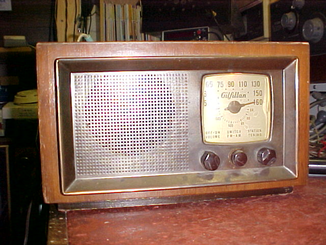
Here's the set without the Radiomuseum watermark. Someone used my site pics there...
Here's the set without the Radiomuseum watermark. Someone used my
site pics there...
This was the second type of mantel set I have acquired incorporating the Fremodyne circuit. It follows the same general design as the Howard 474 in that it's simply a typical US designed AM mantel radio with the FM bit tacked on. As usual, it uses an AC/DC power supply with series heaters and the B+ obtained straight from the mains via a half wave rectifier. In this set, the chassis is "isolated" by means of a .22uF condenser in parallel with a 220K resistor. Not really safe given the reactance of a .22uF condenser at 60 c/s. Anyway, this is really a non issue when used here in Australia, as the set is plugged into a 240V:120V double wound step down transformer. The circuit for the 68F is here.
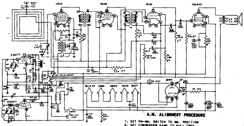
Poor quality due to the original.
As I received the set it looked in fairly used condition. It survived the trip half way around the world reasonably well. The 12BE6 had fallen out of its socket along with its shield and there were a couple of minor splits in the wooden cabinet which were easily glued together. It is an unusual looking set in that it is in a wooden cabinet but with a metal front panel plated to make it look like copper. To get the chassis out isn't as easy as it could be. The loop aerial has to be loosened and pushed towards the chassis, the knobs removed, and then the chassis unscrewed from underneath. It does not come out easily. This is also the first commercially made Fremodyne receiver I have seen to have the Hazeltine Fremodyne Circuit decal. My four others don't have it, although the Hazeltine patent is mentioned in small print.
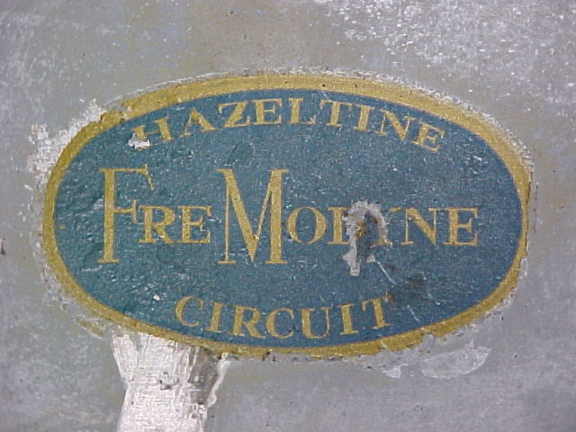
This decal is under the set. Some might think it's an advertisement
for cheap quality.
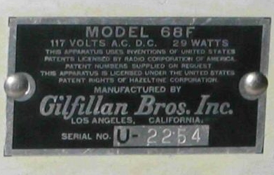
Nameplate riveted to chassis.
Extra loop aerial
One very strange thing was the "extra"
loop aerial. Someone had paralleled the connections of another loop aerial
to the existing one. The additional aerial was just left hanging there.
What this was done for I can only guess. Perhaps the idea was to increase
signal pickup. Problem is that the inductance is lessened and the RF tuning
is basically thrown right out of alignment. Incidentally, the wires were
twisted without soldering.
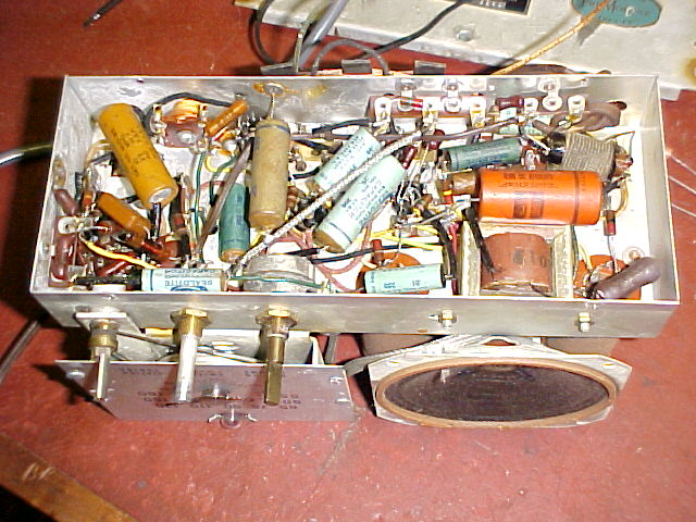
Under the chassis. A metal cover has to be removed first. The brown
electrolytic condenser behind the speaker transformer was added sometime
during the set's history. It proved to be unnecessary.
The internals were all typical...no surprises there. All components appeared to be original. Powering up the set brought in both AM and FM stations, though weakly. It seemed like audio gain was low. Thinking of the Howard 474, and the cathode poisoned 12AT7, I tried another and the FM sensitivity came up considerably. The line cord aerial actually seemed to work quite well and some lower power stations came in quite well. While I haven't measured it, the length of power lead could be a multiple of quarter wavelength in the VHF broadcast band. I did have to replace the mains lead as it had gone brittle in parts and the insulation wasn't the best. The new lead was cut to the same length. Unlike the Howard and Meck sets, the power line aerial is permanently connected in the Gilfillan. There is a short wire emerging from the rear which connects to the power line aerial via a 100pF condenser. What one is meant to connect to this single wire I'm not sure, and not being able to disconnect the line cord aerial wasn't a brilliant idea.
Cathode poisoned 12AT7...again.
So, yet again we can assume that most
of the time this set was used on AM, with lack of plate current for the
12AT7 gradually killing it off. Again, I tried reactivating it in my AVO
valve tester. Emission came up fairly rapidly, and placing it back in the
radio seemed to indicate success with a stronger superregenerative hiss.
However, it soon became obvious that sensitivity wasn't what it was with
the known good 12AT7. It seems that every AM/FM Fremodyne set I get is
going to need a new 12AT7...and I haven't even started work on my second
Howard 474.

The speaker isn't brilliant and really relies on the cabinet baffling
to work properly. The 21.75Mc/s IF coil is at the rear right corner.
Time to replace the condensers.
The new 12AT7 was working well, but audio
was still weak, so time to go through the routine of condenser replacement
and checking resistors. First thing I found was a 30uF electro connected
to the cathode of the 35W4 which wasn't on the circuit, and didn't appear
to be original the way it was soldered in, so I removed it. I changed all
the paper condensers, even though none appeared to be leaky. While doing
this, I discovered this set wasn't exactly the same as the circuit diagram.
Some of the .01uF's were .05uF, and my set is using the three choke version
of the Fremodyne circuit.
One thing I really liked with this set
is the wires aren't twisted around the tags 27 times...and guess what all
you other manufacturers who insisted on doing this...I have never ever
seen a faulty joint where the wire is simply passed through the tag and
soldered.
Powering up again, there was no extra
hum, and the B+ voltage was correct so it would appear that 30uF condenser
was not needed and the existing filters were ok. The audio was still weak
however. Moving onto the Fremodyne section, at last I found something.
The 10uF was o/c. Replacing it brought up the volume to pretty much what
it should be.
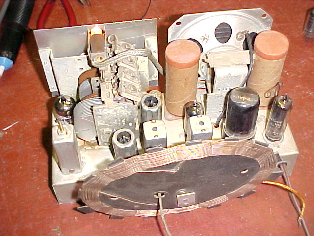
From left to right, valves are: 12AT7, 12BE6, 12BA6, 12AT6, 35L6
and 35W4. The yellow wire is for an external FM aerial, and the green wire
is for AM.
For the AM section, I discovered that the
loop aerial needs to be away from the chassis...the service manual quotes
1.25". Touching up the aerial trimmer helped also.
Checking the IF alignment indicated all
was well there.
Poor AM performance.
Still not happy with the audio level so
time to test all the valves. The 12AT6 and 12BA6 were noticeably weak according
to the valve tester, and so was the 35L6, though only in plate current;
it showed 20mA whereas it should be 40mA. The actual gain was still ok,
however.
I didn't have a 12AT6 or 12BA6 to substitute,
so I used a 12AV6 and 12AU6. The 12AV6 made no difference, so the original
12AT6 stayed. However, there was a useful improvement when I put the 12AU6
in so that's what I left in there. The difference between 12BA6 and 12AU6
is that the 12BA6 is remote cut off and therefore designed for AM receiver
IF amplifiers with the gain controlled by grid voltage (e.g.. AGC or a
cathode bias pot). The 12AU6 is sharp cut off, but in reality I've found
it to work acceptably. The AM section in this set isn't exactly well endowed
with gain so cut off won't be reached anyway, in my area where signals
aren't very strong.
With the chassis back in the cabinet,
the audio performance was much improved with acceptable volume on AM. Distortion
was also much less. It would appear the speaker cone doesn't like to work
without baffling.
Apart from the FM sensitivity, this radio
is a poor performer compared to the Howard.
It really needs an external aerial for
AM; the internal loop is insufficient at my distance from Sydney's MW transmitters
(about 70 km away). Volume is all the way up, or not far from, for comfortable
listening. I won't be using this set for MW DXing!
One annoying thing was the AM/FM rotary
switch. When will manufacturers stop using round section shafts which allow
the knob to slip? This radio was no exception, and it seemed that over
the years the knob had needed to be tightened to the point of the knob
breaking. I filed a flat into the shaft to reduce the problem and glued
the knob back together, but eventually I can see the knob having to be
replaced.
The heater circuit.
One thing I noticed when I first turned
the set on was the dial lamp flickering at 50c/s. It was like a diode had
been used as a heater dropper, but I quickly realised that there'd be no
need with the valve heater voltages adding up to about 120V. I then noticed
on the circuit that the dial lamp was fed off a tapping on the 35W4 heater,
and was also in series with the AC supply to the 35W4 plate. I'd seen mention
of this technique many times, but this was the first radio I'd acquired
that used it. One of my Meck converters also has a 35W4 but there is no
dial lamp, so never really thought about it before. It seems to be something
of a compromise to power the dial lamp this way, and also explains why
the lamp is dim when first turned on...most of the lamp current is from
the B+ . It makes me wonder about the design of the 35W4's heater if it
can put up with such a variation of current. The reason why the dial lamp
can't just be put in series with the heaters is because of the switch on
surge. When cold, the valve heaters have low resistance, thus forcing too
much current through the dial lamp.
The European method is to have a thermistor
to reduce the switch on surge. As the thermistor warms up due the heater
current flowing through it, the resistance decreases to a low value. The
other method is to put a resistor in parallel with the dial lamp to absorb
most of the surge. However, it means the lamp is under run once the heaters
have warmed up and is dim. The Howard 474 uses a thermistor since it has
a selenium rectifier.
Gilfillan vs. Howard.
So how does this radio compare to the
Howard 474? Well, it looks cheap. The cabinet must have been designed by
Blandness Inc. because it's just plain veneered plywood built into a simple
box shape. The Howard has an attractive bakelite cabinet with some detailed
features. Also, the Howard has instructions on aerial connections, and
the FM aerial is not permanently connected to the line aerial. The Gilfillan
just has two wires hanging out of the bottom of the cabinet. The Howard
uses a choke for B+ filtering while the Gilfillan uses a resistor. Not
that this is a bad thing, but it does indicate cost cutting. The thermistor
in the Howard's heater string is a sign of thoughtful design, and less
concern with cost cutting.
Nevertheless, the Gilfillan is nice set
to have, and any Fremodyne is welcome in my collection.