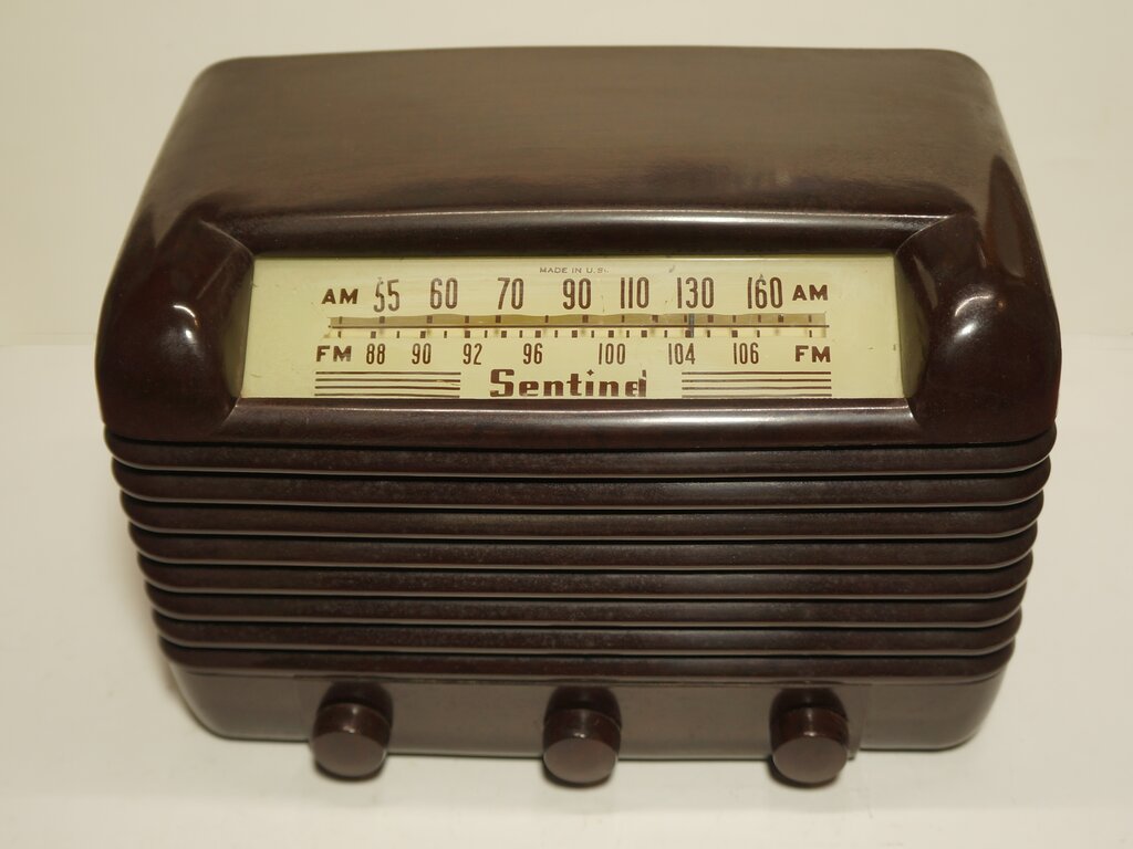
The Sentinel 315-W (walnut) or 315-I (ivory)
was another example of a low cost AM/FM mantel set incorporating a Fremodyne
FM tuner. Before reading further, if you have not already done so, please
read the Fremodyne
page to acquaint yourself with the unique method of FM reception used
in this set.
Like all my other commercially made Fremodyne
receivers, this one was bought off Ebay in the U.S. and arrived in Australia
a couple of weeks later.
First impressions were the set had hardly
been used, for the cabinet was in perfect condition. Either that or it
had been carefully polished. Of course I had to try it out, and plugged
it into a 110V transformer I had handy. All I was greeted with was a very
loud hum, and one which wasn't controllable by means of the volume control.
No modulation could be heard behind the hum, suggesting the front end wasn't
working either.
However, that was all no surprise given
all the leaky condensers likely to be in the set.
Once I got the chassis out of the cabinet
and looked underneath, I noticed how bare it seemed to be. I also noticed
that the 35L6 cathode bypass condenser had been replaced.
It's been got at!
First thing was to sort out the atrocious
hum; and that's when I'd found this set had 'been got at'. I went looking
for the main filter electros only to find they were not there. No wonder
it hummed! And no wonder the chassis looked bare!
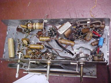
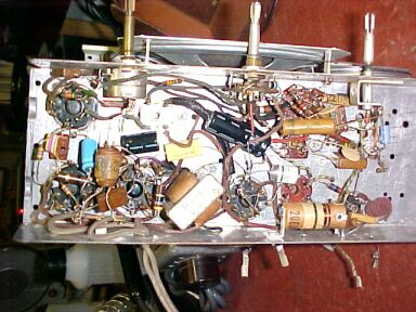
Under the chassis. There should have been a multi section filter
condenser in front of the speaker transformer.
A closer look revealed some strange things. Our butcherous friend should never have been let near this radio. Starting with the FM tuner, the 150K resistor had been cut and joined back together. Not only that, for some strange reason the FM section has been disabled altogether. Notice in the above pic the red wire with black insulating tape just behind the centre control (the AM/FM switch). That's the B+ feed to either the AM or FM tuners. Our friend had decided to remove this wiring from the switch and permanently join the B+ to the AM tuner. Why?
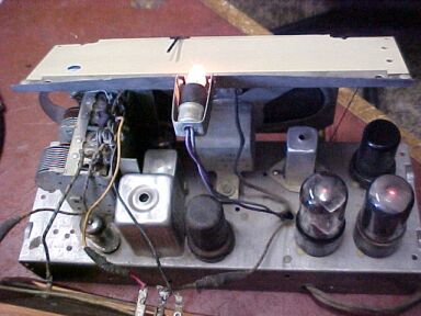
Top of the chassis shows typical US mantel radio design. From left
to right the valves are 12BE6, 12SK7, 35Z5, 35L6, and 12SQ7 at the top
right. The 12AT7 is hidden between the speaker magnet and tuning condenser.
The previous dial lamp wiring was in danger of shorting out so was replaced.
Replacement of the paper condensers was
all routine with a few other surprises along the way. The 47R resistor
in series with the 35Z5 plate had been replaced, suggesting the B+ might
have had a short at one time. The RF bypass mica condenser at the volume
control wiper had one of its leads cut and was just left there. As for
the main filter electros, I used separate condensers scattered around the
chassis. The original type of filter condenser is one not used in Australia.
It consists of a cardboard tube with two or three condensers inside, connected
by flying leads. Mounting consists of a strap riveted around the case which
is then secured to the chassis. As every one of these I've seen in other
pieces of equipment was open circuit, my guess was that the one in this
set would have been too. I have to say it, but had it been an Australian
radio, the filter caps would most likely have been ok.
Next piece of butchery was the 2nd IF
transformer. It looked to be a replacement given the fresh soldering on
its lugs and the fact it didn't fit properly.
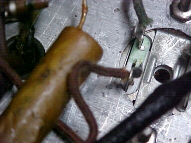
Here's a good example of the bodgie work done on this radio. The
replacement 2nd IF transformer was a bit too big for the existing hole.
The fact the lugs touched the chassis didn't seen to worry the previous
"restorer". The lower lug carries the B+.
The other thing which attracted my attention
was the gouge in the side of the aluminium case. Again, why? It didn't
look deep enough to damage the windings inside.
Not only did the transformer not sit on
the chassis properly, but no matter how one moved it around, at least one
lug was touching the chassis. So, I nibbled out the hole to provide more
clearance which also allowed the transformer to fit correctly.
The dial lamp wiring was in need of replacement,
having become brittle and already cracked. With the design of the heater
supply in these American sets, a short here would ruin the rectifier valve
heater.
Butchered Aerial Coil
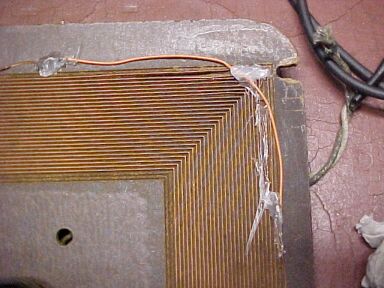
The AM loop aerial. Another example of incompetent butchery. Shorted
turns galore here!
In between working on the rest of the radio,
I'd been gradually rebuilding one corner of the AM loop aerial. This was
another area needlessly butchered. How the loop could have been damaged
like this is a mystery. It is of unusual construction where copper strip
has been virtually stamped into the masonite back. No adhesive seems to
have been used, and given the way it's constructed it would surely be an
expensive way to make it. Mr. Butcher had attempted to repair the coil
simply by gluing the turns into place, and bridging a missing part with
wire. Fair enough, but looking close I could see adjacent turns touching.
Not good for the Q! So, I pulled off all the glue and straightened out
the winding, this time using super glue to hold each one on the correct
position. I used tinned copper wire to bridge the missing part, and did
it somewhat more neatly. But I just wonder what sort of treatment caused
the aerial to be like this in the first place.
Under the chassis after condenser replacement. The only paper condenser
left was the audio coupling from the Fremodyne detector.
At last it was time to test. Much to my
surprise, the FM part worked straight away. For once, I hadn't been left
with a cathode poisoned 12AT7. Sensitivity and sound quality were of typical
Fremodyne quality. The thin paper speaker cone didn't help and I guessed
this was another set that won't give good bass response outside the cabinet.
Why is it that US made speakers have such
thin paper for their cones whereas the Australian ones are much thicker
(and sound better)?
Apart from that, it did seem something
was microphonic and there seemed to be some intermittent frequency drift.
IF Transformer Faulty.
Turning to AM and it was just a hopeless
loud scratching noise with nothing receivable.
Shorting the primary coil of the 1st IF
transformer didn't kill the noise, but shorting the grid of the 12SK7 did.
So, it looked some problem with the IF transformer. Removing the 12BE6
and it was still there. It was like there was a breakdown between windings,
so I removed the transformer and dressed the leads from the primary and
secondary coils away from each other. Much to my surprise there was still
leakage. Then I started to think about the tuning condensers. Sure enough,
this was where the problem was; yet another unreliable mica condenser.
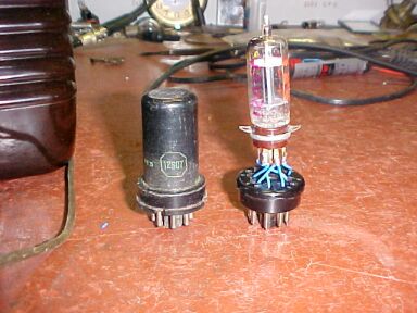
The first IF transformer with new polystyrene tuning condensers.
To the right is the original mica unit shared by both coils. It was leaky.
I measured the values to find both 100pF
which is what I expected. In with some new polystyrenes and noise gone.
And I could receive AM stations!
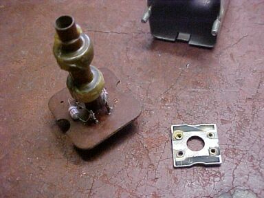
While the set was running, I noticed a
variation in dial lamp brightness. It seemed to have something to do with
the 35Z5 as moving this valve caused the fluctuation. Resoldering the pins
didn't help, so I had to extract the glass from the base to check the wires.
Luckily, all the cement had lost adhesion so it wasn't too difficult. All
checked out ok so I refitted the base and all was well. I use a few turns
of insulating tape to secure the glass to the bakelite base after this
sort of repair, just in case the base has to come off again. After a few
hours of heat, the tape makes a strong join.
I was reminded while doing this how limited
these U.S made AC/DC radios are with their dial lamps. The tapped heater
of the rectifier valve only allows a single 150mA dial lamp. Contrast this
to the typical Australian transformer powered set with two 300mA lamps.
The AM section all lined up ok so then
went back the FM and its drift problem. First thing was the local oscillator
trimmer screw was making bad contact, which also made alignment difficult.
The drift was still there after fixing that. Then I was about to replace
the 20pF across the oscillator coil when I noticed it was touching the
coil. Knowing the insulation of this sort of ceramic condenser might not
be 100%, I moved it away. Since then the FM section has been perfect.
Microphonic Valve.
At last it looked like the end was in
sight for the work on this set. All along the microphonic problem had been
evident and it seemed to be coming from the 12SQ7. It was worse on AM too.
Just the slightest touch would send the thing into an awful howl, let alone
having the volume turned up. Not having a 12SQ7, I made an adaptor to substitute
a 12AV6, which is just the 7 pin version of the 12SQ7. As it turned out,
the 12AV6 needed to be shielded to reduce hum pickup, something taken for
granted with the metal 12SQ7.
The 12AV6 replacement for the microphonic 12SQ7.
Now the microphonic problem was sorted there was yet something else. The AM gain was varying all over the place intermittently. As it seemed to be between the 12SK7 and detector, I thought of the previous IF transformer problem. So out with the replacement 2nd IF and was surprised to see that it too had one of these mica condensers with the same mica shared by both windings. Not only that, but connection to these condensers was merely by spring loaded contacts. Again, this was removed and replaced with the polystyrenes, allowing the AM to function peacefully again.
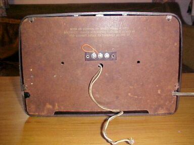
The back of the Sentinel 315. From left to right the terminals are
FM, power line aerial, and FM earth. The writing above reads, "When
an external FM dipole is used disconnect jumper connecting terminals #1
and #2 and connect dipole to terminals #1 and #3". The flying leads
emerging beneath are the AM aerial and earth.
The Circuit.
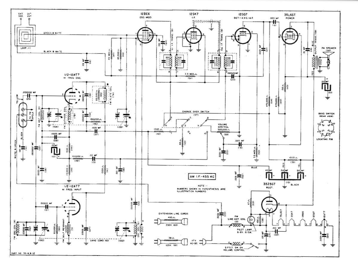
For a better quality circuit, see here.
Power Supply.
At first glance it's a typical circuit
of an American AC/DC set with Fremodyne FM section. This one has more in
the way of octal valves than the Gilfillan 68F or Howard 474, despite being
the same age. Starting with the power supply, it follows usual practice
but this time the chassis is connected direct to the power line without
a separate earth busbar isolated from the chassis by means of a condenser.
That's fine as the chassis is fully enclosed in this set. There is also
an RF isolating choke in mains input to allow the mains lead to function
as a power line aerial. This has been a feature of every Fremodyne set
I've seen so far.
Unsafe Operation.
Interestingly, on the circuit diagram
is shown the option of an extension line cord resistor to allow 230V operation.
Given the construction of this set, there's two things I don't like about
this. Firstly from an electronic point of view, an AC/DC set does not draw
the same current on the positive and negative parts of the AC waveform.
This is due to half wave rectifier causing asymmetrical loading. Then there
is the fact that the current drawn by the radio when first turned on is
less than when the valves have warmed up and B+ current is being drawn.
So, the valve heaters are likely to receive a higher voltage when the set
is first turned on. Thus the value of this resistive line cord dropper
has to be something of a compromise.
The next issue is that of safety. The
isolating condensers are unlikely to be suited to 230V operation, and that's
what voltage they'll be exposed to depending on whether the set is switched
off at the volume control and/or the polarity of the mains plug.
The AM aerial coil primary is not very
well isolated either, with less than a millimetre between it and the rest
of the winding. Or what if something metallic should bridge across the
windings?
The fact the knobs can be easily pulled
off is another issue. The best way to operate these sets off 220-250V mains
is to use an isolated step down transformer.
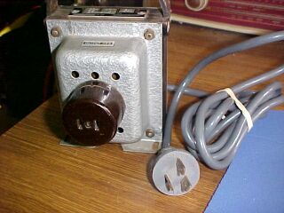
The correct way to operate U.S equipment off Australian 240V mains.
This transformer is double wound and can provide 100W.
The AM Section.
Nothing too weird here, except the initial
bias for the 12SK7 comes from the negative voltage developed on the 12BE6
oscillator grid. As is popular with U.S sets, a loop aerial is used.
The FM Section.
The Fremodyne receiver has been covered
elsewhere. This one is no different, except I notice the IF is tuned to
27.75Mc/s and not the original 21.75Mc/s. Incidentally I didn't have to
fine tune the quench frequency in this one as the subcarrier beat is hardly
evident. This set also uses the simpler two choke circuit.
Obviously they don't worry about the unbalancing
of a 300 ohm transmission line when an external FM aerial is connected,
with one side going to earth and the other to the RF input.
The thing that did attract my attention
was the AM/FM switch. What's with the third pole and 68 ohm resistor? It
looks like they want to discharge the FM filter condenser quickly when
switching to AM. But why the 68R? The discharge current will be limited
by the existing 1000R decoupling resistor.
The Audio.
A bit cheap here unfortunately. No negative
feedback and a rather low grid condenser for the 35L6 giving a very trebly
response. This radio is thus unpleasant to listen to outside of it's cabinet.
The thin paper of the speaker cone doesn't help either.
Performance.
The AM is typical of these sets. The sound
quality isn't hi if by any means and the RF sensitivity not brilliant.
Not the sort of thing for DX. The FM is like the other Fremodynes
with similar sensitivity and sound quality which is quite good at times.
The power line aerial works with the stronger stations well enough, but
of course moving the mains lead has an effect on this. So far, out of the
Gilfillan and this set, the Howard is still the best overall performer.