This unusual inverter came to me via a
fellow HRSA member. Where and how it was originally used is a mystery because
it is obviously not intended for use by the general public.
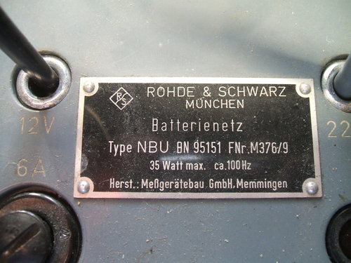
Rohde and Schwarz is a well known manufacturer
of high end radio test instruments, so it is quite possible the inverter
was designed to power one of these from a 12V source.
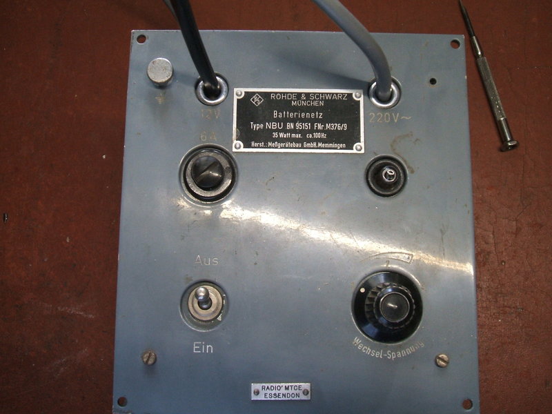
The only clue to its past is the label
riveted to the case, "Radio MTCE Essendon". MTCE most likely means "maintenance".
Essendon is the site of one of Melbourne's smaller airports, so it's conceivable
the inverter was used in the aeronautical environment. Given the shape
of front panel with four holes, and the leads emerging from the front,
it does suggest some kind of rack mounting system was used.
Input is 12V DC and output is 220V AC.
With a maximum output of 35W and a frequency of 100Hz, it was more than
likely a car radio vibrator was used.
Some variation in output voltage is available
from a three position switch, to accommodate for the lack of regulation.
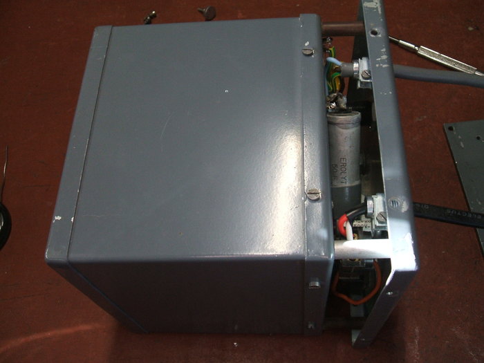
The first surprise upon opening the unit is the dual shielding arrangement. The inverter is a box inside a box. This is no surprise given that R&S would have paid attention to RF shielding more than other manufacturers - especially if the inverter was to drive test instruments.
Do not use 250VAC self healing capacitors as I've shown here. Their
capacitance drops over time as the dielectric is punctured by spikes on
the waveform. These were replaced after the photo was taken. See end of
article for details.
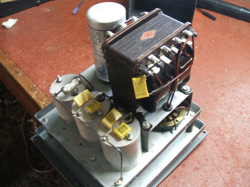
Opening the second box reveals the internals,
and again the R&S quality shows. The three cylindrical components are
the RF chokes. It's not very often you'll see chokes shielded in an inverter
but again demonstrates the quality.
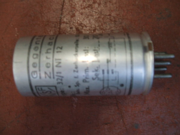
The vibrator is indeed a car radio type.
Thoughtfully, its manufacturer has printed a diagram of its pin connections,
and provided the maximum ratings. Good design follows through with the
driving coil being series driven. There is a 1950 date stamp on the vibrator.
The Circuit.
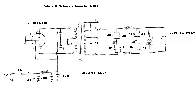
The circuit is completely conventional
but with extra attention paid to filtering. The input is fused at 6A, and
filtered with a PI type filter. The combination of 50uF and .01uF condensers
ensures that both low and high frequency noise is filtered. As electrolytic
condensers do not perform so well at RF, the parallel .01uF takes care
of the high frequencies.
The vibrator is quite standard being a
series driven non synchronous type. The only unusual thing perhaps is the
European 5 pin base.
The transformer has three output tappings,
selectable by the rotary switch on the front panel. Buffer capacitance
is made up by the combination of .01 and .05uF condensers in the secondary
circuit. In the primary circuit are two can type condensers which are unmarked.
Measuring one showed a value of .432uF. In reality, it would have been
designated .4 or .5uF. These would provide a small proportion of buffer
capacitance but would be included mainly for RFI suppression.
The output is balanced and includes chokes
in both output lines, forming two PI filters with the buffer capacitors.
A neon lamp connected to the output shows the inverter is operating.
Restoration.
Both the input and output cables had to
be replaced as they had been cut off. What remained was brittle and crumbling
rubber anyway. Given the output was rated at 220V, I fitted a normal 3
pin socket to the output cable to run normal 240V appliances.
Upon powering up, the vibrator had to
be given a little thump to start it as it had not been used for a very
long time. Although the reed was now vibrating reliably, the contacts were
covered in insulating film so no output was produced. As the can is of
the crimped type, I didn't want to open it, so instead cleaned
the contacts electrically as described here.
This was completely successful and there
was now output. The .01uF and .05uF capacitors looked unusual being in
a ceramic tube. It was not entirely clear if the dielectric was also ceramic
or if it was paper. Regardless, they were leaky. In fact they were leaky
enough to dimly light a light bulb connected from each output line to earth.
The capacitive reactance on its own would not be able to do that.
All the high voltage capacitors were therefore
replaced.
The original switch had been damaged to
the point of being unrepairable, so was replaced with a standard toggle
switch. A small aluminium plate had to be made up to mount it on, riveted
to the case due to the much larger hole used by the original. The front
lens of the neon indicator had been long broken off and lost, but the neon
bulb itself was undamaged.
Performance.
This inverter works as intended and is
unsurprisingly free from RFI. In fact, it is used to power the Xmas
box mantel receiver and the Minivox
off my solar lighting
plant. The output voltage, even on the lowest setting is closer to
240V than 220V which is all to the good.
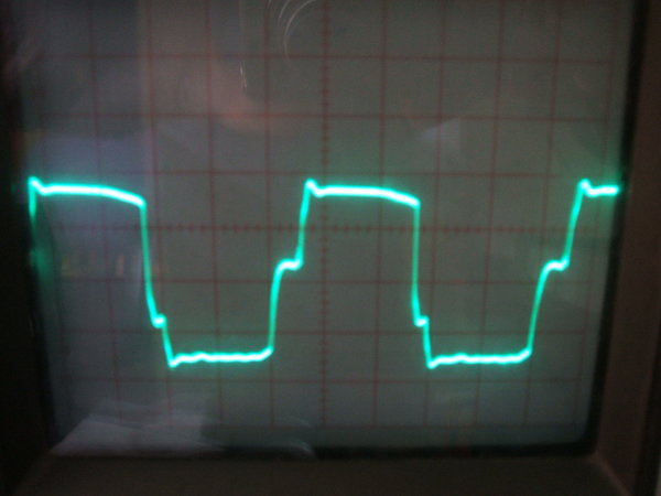
Output voltage waveform under load.
The output waveform looked reasonable on
load, being typical of where the transformer is supplying a resistive load.
The resistive load discharges the buffer capacitance in between voltage
peaks, so the straight line as found in DC to DC converters, or unloaded
AC inverters does not apply. However, it was felt further investigation
was warranted, because using an open test vibrator, some arcing was evident
under no load.
With a current meter in the 12V supply,
the value of buffer capacitance was tested for suitability by looking for
minimum current.
It was found that 16uF added across the
transformer primary gave a very nice waveform, and minimum current consumption
on no load; about 600mA. Arcing was eliminated, both on load and off load.
This indicated that the original value of buffer capacitance was inadequate.
However, given the cost of 16uF worth
of polyester capacitance, and the difficulty of fitting such into the existing
enclosure, this idea was dropped. Instead, .1uF was added across the secondary,
giving in total .15uF across pins 5 and 8. Although the results weren't
quite as good, they were acceptable. It is generally better for the buffer
capacitance, or as much of it as possible, to be across the primary winding,
so that it is not influenced by transformer characteristics.
It should also be noted that all the yellow
self healing 250VAC capacitors I had used for the original restoration
were replaced.
While the 250VAC rating looks enticing
for buffer capacitor replacements, the problem with this type of capacitor
is that each time the dielectric "heals" a small portion is actually burnt
away. The result is a gradual loss of capacitance over time. Indeed, the
loss of capacitance was measurable with the ones I took out of this inverter.
Obviously, this is undesirable for buffer use. I replaced them all with
2000V polyester types. I have not had any failures with these.