Someone's attempt at building the Radio & Hobbies "Minivox". I subsequently added a proper volume control.
Someone's attempt at building the Radio & Hobbies "Minivox".
I subsequently added a proper volume control.
This set came to me via the free pile at
an HRSA meeting some time around 2001-2002. It was devoid of any
valves and dial lamp, but all the rest was there. It was immediately recognisable
as a regenerative receiver, having only one coil, a Reinartz coil made
by Permatune. A quick trace of the circuit revealed it was a Radio &
Hobbies project called the "Minivox", presented in December 1947. It was
intended to be the smallest mains operated receiver that was practical,
and indeed the cabinet dimensions were quite small.
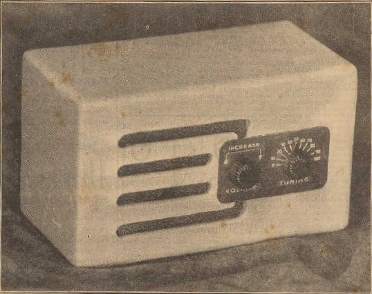
This was the smallest mains operated, loudspeaking valve receiver
ever described in R&H. A plastic dielectric tuning condenser
was used to save space.
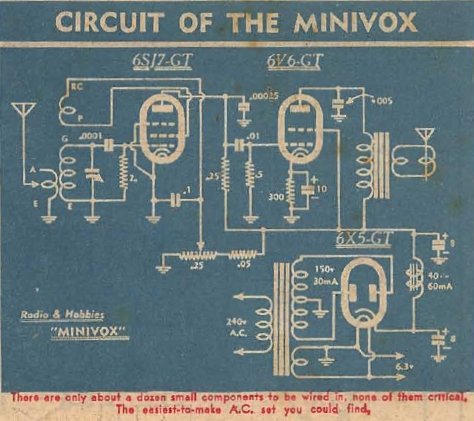
A truly minimalist, but practical circuit.
The design.
As can be seen from the circuit, it is
a very typical regenerative detector driving an output valve. The circuit
is virtually identical to the "Tiny Tim II" described here.
However, there are some important differences
in terms of physical construction. Firstly, the Minivox was intended only
as a broadcast receiver, and the coil was a commercially made type with
litz wire and ferrite core - thus supposedly providing higher performance
as compared to air wound coils. "GT" style valves were standard by the
time the Minivox appeared, which was beneficial in keeping to a small size.
The shorter envelopes of the 6SJ7 and 6V6 compared to the 6J7 and EL3N
allowed for a reduction in cabinet height. Likewise, the 6X5GT was shorter
than the 5Y3G. A 150V a side transformer was of course smaller than the
325V a side type used in the Tiny Tim II. The normally large tuning condenser
was replaced by a miniature imported English type with plastic dielectric.
One not so desirable feature was the absence
of a volume control. Here, it was intended that the regeneration control
would function thus. It will certainly do that, but at the expense of selectivity.
Radio & Hobbies way out of that deficiency was to recommend an aerial
as short as possible.
The circuit.
The tuned circuit consists of a commercially
made Reinartz coil and single gang tuning condenser. Reinartz coils were
made by all the usual Australian companies, such as Aegis, Q Plus and Permatune,
for simple regenerative designs which were always popular among home constructors.
There are usually two aerial connections provided on such coils. One is
for short aerials and is usually a tapping on the secondary winding. This
gives a much tighter coupling than the conventional "long aerial" connection,
which is a conventional primary winding of few turns. In this way, some
flexibility in aerial matching is provided to obtain best results. This
is particularly important in very simple one valve sets where every bit
of gain counts.
A conventional grid leak detector using
a 100pF and 2M is used. The detector valve chosen is a 6SJ7, sharp cut
off RF pentode. It is essentially the same as the 6J7 but without the top
cap. Plate load is 250K across which the demodulated audio appears. RF
is bypassed to earth by 250pF. Regeneration is obtained by varying the
screen grid voltage, and thus the gain of the pentode, while feedback is
obtained from the RF present at the screen grid. This gives an extremely
smooth control, unlike the common method of using a variable condenser
in series with the feedback winding. As I've said before, such designs
give regenerative receivers a very bad reputation. Using a variable condenser
to adjust regeneration results in considerable backlash and detuning.
As regeneration provides a considerable
increase in gain, and thus demodulated audio, it is natural to assume that
as regeneration is reduced, so is the volume. Indeed, the regeneration
control is used a a volume control. The trade off is that as regeneration
is reduced, so is selectivity, and at low settings, the selectivity may
be no better than a crystal set. This was done to suit non technical users
who always have difficulty in adjusting a regeneration control to the optimum
position, and then adjusting a volume control. Used by a non technical
user, the Minivox controls would function like that of a two knob superhet
which anyone can operate. Of course if the "volume" is increased too far,
the set breaks into oscillation. Hopefully the signal is strong enough
to provide a sufficiently loud volume before that happens.
The detected audio proceeds to the grid of a 6V6 output valve, via a .01uF condenser. The 6V6 bias is obtained from a 300R cathode resistor. This is higher than the usual 250R, but the increased bias allows a smaller lower current power transformer to be used. The power supply is conventional, using a 6X5 rectifier and 150V aside power transformer. Choke filtering is used. Had high value filter condensers been easily available, the choke could have been replaced with a resistor, further saving space.
My Minivox.
The receiver I acquired from the HRSA
was obviously home made, but quite well done for what it was. The chassis
was aluminium and had been brushed in grey enamel. It looked like it had
been bent up in a home workshop given the simple folds, but a good job
had been done.
Physically, it was somewhat larger than
the Minivox, with dimensions similar to an ordinary size mantel set. A
conventional tuning gang had been used, although fitted with a reduction
drive. The speaker cone had been damaged, and with a missing dust cap,
particles had found their way into the voice coil. The valves and dial
lamp were missing. At this stage, I hadn't identified the set as the Minivox,
but it was pretty obvious what the valves should be. For the rectifier,
the heater was fed from the same winding that fed the other valves
and dial lamp, and the pins matched a 6X5. For the output, there's a few
valves which share the same pin connections, but with a 300R cathode resistor,
6V6 would be the likely candidate. The detector took a little more thought,
for there was no grid cap connection. Obviously it was a single ended valve,
and given what was fashionable at the time, a 6SJ7 or 6SK7 would be possibilities.
Because we want a sharp cut off valve in this position, that narrowed it
down to a 6SJ7.
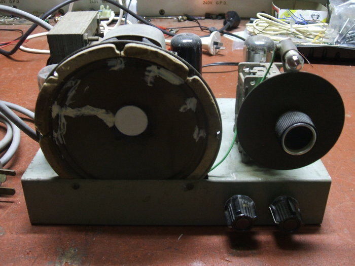
The two aerial terminals are visible next to the 6SH7 detector.
To the right is the 6V6, and in the top corner is the 6X5.
I found some suitable valves, although
ended up using a 6SH7 for the detector, simply because one was close to
hand. This has the same connections but is a higher gain valve. A 6AC7
would also have done the job. I doubted the latter two types were intended
for the original design as they were at the time seen only in professional
or military equipment.
With all original components in situ I
then powered up the receiver. It performed as expected with the typical
gain and selectivity of a regenerative detector. There was no evidence
of leaky paper condensers, so I left them in. Normally, I would immediately
remove such things and replace them, but given the non critical circuit,
and the lower B+, plus the paper condensers are of a type that are actually
fairly reliable, I decided to keep it all original. The only critical condenser
is of course the 6V6 grid coupler, but as I'm the only user of the receiver,
any distortion will not go unnoticed if it should start leaking. Likewise,
I haven't bothered to fit a fuse because if anything untoward happens I
will be aware of it and switch off before damage occurs.
For the dial lamp, I fitted a 12V bulb,
as a 6.3V type was too bright with no cabinet to shield it. It is doubtful
there ever was a cabinet for this set, and some radio station call signs
had been penciled in on the brass disc which functioned as a dial.
It appears the set had been made just
after the introduction of plastic insulated wire, but at the same time,
the resistors and condensers were older. The resistors were of the body
end dot type. One could assume it was made with parts to hand. This is
especially evident where the detector plate load consisted of two parallel
500K resistors instead of one single 250K.
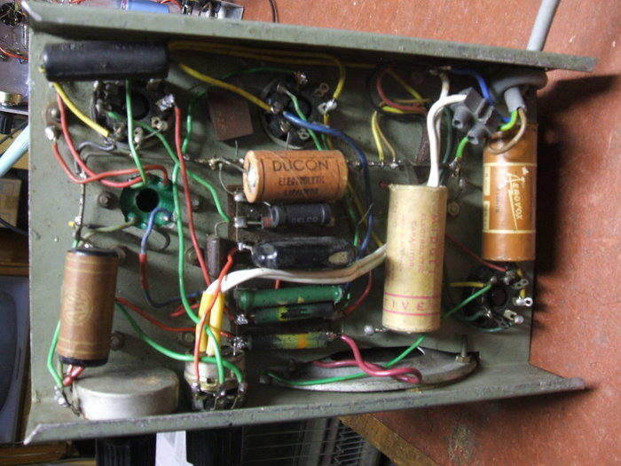
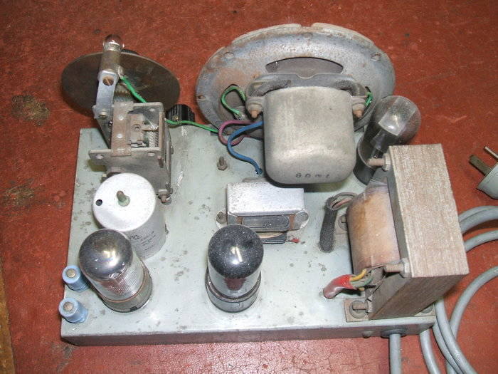
Under the chassis, all components are original except for the volume
control and power cable.
The speaker succumbed well to repair. The
particles in the voice coil gap were extracted using strips of overhead
projector transparency film. By bringing the particles up to the top of
the magnet, they could be picked off with tweezers. Having done that, a
cardboard dust cover was made and glued into position. Next, all the tears
were dealt with by repairing with silicone sealant. This is ideal because
of its flexibility as well as adhesive qualities. Sound quality was now
as it should be.
Not being a fan of controlling volume
with regeneration, I later installed a 500K pot, complete with power switch,
to take over this function. Now, the detector could be operated at maximum
sensitivity and the volume controlled independently.
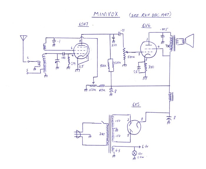
Circuit of the set after I added the volume control/power switch.
Note the 250K plate resistor actually consists of two parallel 500K's.
The regeneration pot had no marking but measures 150K - a non standard
value. It could actually be, and probably is, a 250K type that has reduced
in value. Either way it is in no way critical. It is probably coincidental
that the 50K resistor in series with the regeneration pot is a 40K in this
set. It would make up for this.
This is one of those sets that looks a bit rough, but just keeps working day after day, always dependable.