 ..
..
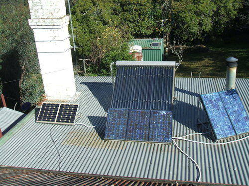
From left to right, panels are: 2x 40W, 3x 40W, 2x60W, 2x60W. The evacuated tubes for the water heater are behind the 3x 40W panels.
This is one of those projects that I've taken years to actually get around to doing. As someone who objects to paying huge profit making organisations for services, as well as wanting a degree of self sufficiency, this article describes some steps towards doing that.
..
From left to right, panels are: 2x 40W, 3x 40W, 2x60W, 2x60W. The
evacuated tubes for the water heater are behind the 3x 40W panels.
For years I've been accumulating and building
things that run on 12V, and my garden shed has had a simple 12V solar power
installation since 1999, so 12V was the natural choice for the house system
which I set up in 2005.
I have noticed over many years the poor
installation of 12V systems resulting in the impression that they're a
very poor compromise and not really practical. The reason for this is voltage
drop in the wiring. Unfortunately, because the voltage is low and not dangerous,
all sorts of scraps of wire get used. The problem is that for a given power,
an appliance operating on 12V draws 20 times the current than if it worked
on 240V. So, the voltage drop along the connecting cable is far more significant.
The fact that there aren't as many volts to start with really shows up.
End result is dim lights in many installations. Another thing that taints
so many solar installations is the use of cheap and low powered lights.
Those 8W fluorescent lamps so often seen in boats and caravans are a good
example. The light output of these is considerably less than the 240V equivalent.
And the use of light bulbs meant for automotive use gives one the impression
of living in a dark cave. Automotive bulbs are not designed for general
illumination; and neither are 'signal' or 'pilot' type bulbs.
My system was to have none of this. By
careful planning it is quite possible to wire up a house for 12V, and not
feel the system is a compromise.
The Solar Panels
The heart of the system is of course the
solar panels. I have acquired 400W worth of solar panels. The first set
are three 40W panels which I attached to a steel frame I welded up, using
only lead acid batteries to provide the welding current. Being ordinary
mild steel, I then painted the frame with cold gal. Not as good as the
real thing, but better than anything else I could paint it with. The whole
assembly was hauled up onto the roof and pointed north. These 40W
panels go back to the mid 1980's. Later, another two 40W panels were added,
bringing the total up to 200W.
Later again, two more 40W panels were added
(280W total), and then another two 60W panels (now 400W total). All the
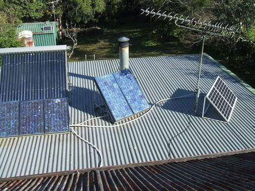
40W panels face north east, and the 60W panels face north. This gives useful
output for most of the day. Because of trees, there is no point having
panels facing west. The positioning was set up at the time of year when
the days are shortest, since the roof shadow from the main part of the
house blocks out sun for a lot of the morning, if the panels are too far
forward. The two right side panels also have to be positioned so as not
to block the sun to the evacuated tube collectors for the water heater.
While the possible output from all the
panels is 400W, this never happens in practice. Firstly, the positioning
of the panels is such that they do not all receive full sunlight at the
same time. Also, the power rating for solar panels is at their open circuit
voltage; about 18-20V for 12V panels. The power output is reduced when
connected directly to the batteries since the maximum voltage is around
14.5V. Modern microprocessor controlled charge regulators contain a switchmode
converter to allow the panels to develop more power by allowing them to
work at their most efficient voltage. I describe these later on.
Wiring
This was the key to the whole thing being
usable. Insufficient wire gauge would be a recipe for dim lights. Working
out the length of the longest run and allowing a one volt drop at 10A,
I calculated that 16mm cable would be acceptable. To further improve the
situation, I decided on a ring main. For those unfamiliar with this, a
ring main is essentially a loop which starts and finishes at the source,
with loads tapped off along the way. What this means is that at the most
distant load, you have halved the voltage drop since there's two sets of
conductors in parallel feeding it.
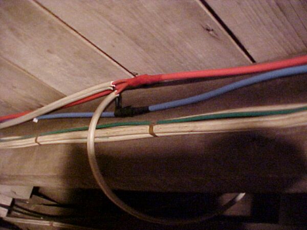
The red and blue conductors are 16mm single insulated building wire
running around in a loop under the house. You can see a tap off where two
sets of 2.5mm TPS cables feed nearby sockets. Beneath is the existing 240V
wiring.
I spent a weekend attaching the 16mm conductors to the floor joists under the house. The tap offs to the wall sockets inside the house were done with short lengths of 2.5mm TPS cable. The 16mm wires were stripped, the 2.5mm wires wrapped and soldered around them, and covered in tape. The joints were staggered to prevent shorts should the tape come off. I avoided any form of screw connector, knowing of the higher resistance connection these provide.
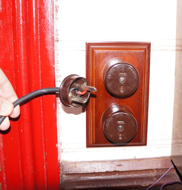
An example of the 12V sockets. I used period repro mounting blocks
and bakelite sockets to keep in with the style of the house.
Sockets
Australia fortunately has a standard Extra
Low Voltage (32V or less) plug and socket configuration. Like our 240V
socket, the ELV socket is also of U.S. origin. It is further described
here. It's known as a "T socket" or by the Clipsal part number 482/32.
Current rating is 15A and rugged construction means these fittings are
far superior to any form of cigarette lighter type of connector. The fact
they are constructed and installed like other domestic electrical fittings
means they are unobtrusive inside the house. Surface, flush mount, and
cord extension sockets are available in this configuration. Despite this,
there are many horrifying examples of ordinary 240V power points being
used for 12V. It seems to be common practice overseas, particularly, to
use mains type sockets for alternative energy installations. Pity the poor
appliance when it gets plugged into the mains! Not only does the appliance
suffer damage, but most 12V appliances have exposed parts connected to
the supply, exposing the user to an electric shock when plugged into 240V.
The "T" fittings are available from all electrical wholesalers, and from
some alternative energy, caravan, and boat accessory suppliers, so there
is no excuse not to use them. Shop around, especially if buying on eBay,
since some are grossly overpriced. These fittings had their origins back
in the days when many Australian rural homes had their own 6-32V lighting
plant. Despite this, many installations persisted with the three pin 240V
type instead!
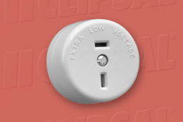
Australian standards stipulate that the top pin is positive when
used with DC. The bottom pin is negative or the earthed side of the supply.
To fit in with the existing 1930's style electrical fittings in my house, I mounted a pair of brown 482/32 sockets on reproduction wooden mounting blocks, and installed them adjacent to the existing 240V power points in each room.
Lighting
The light circuit was also run using the
ring main technique, with a loop of 4mm cable in the roof. This was fed
by a 4mm run from under the house. As I am a firm believer in the beauty
and light quality of incandescent lamps, I elected to install them in each
room. No politically correct compact fluoros here! To be practical, small
incandescent bulbs as used in caravans or the like just aren't acceptable.
The lights had to be as bright as the 240V counterparts. For many years,
GLS (household style) incandescent lamps have been available in 12V among
other low voltages. They have been available in ordinary B22 bayonet cap
or E27 Edison screw. Not only is their light output the same as the mains
equivalent (actually slightly higher for the same wattage), but it means
you can use ordinary domestic light fittings in an extra low voltage system.
12V incandescent bulbs in GLS style with a B22 base are no longer made
in Australia, but I have a life time supply of them. Crompton was the last
supplier, switching to Chinese production, but even these are no longer
available. A few places still have old stock. They're also still available
in the U.S. with an E26 base, but probably won't be forever.
These days, there has been a marked switch
to LED bulbs for low voltage systems. At least they are available with
E26/E27/B22 bases so "mains style" fittings can be used with them. 12V
bulbs with BC/ES bases are also now available with LED filaments and in
the GLS style, so these are a pretty good substitute.
These 50W 12V lamps work as well as their mains powered counterpart.
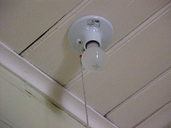
To save disfiguring the walls with extra switches, and to reduce the amount of wiring (i.e.. voltage drop), I used pull chain lamp sockets. As these have never been a standard fitting in Australia, I bought them from the U.S. Of course it meant that Edison Screw bulbs have to be used. It just so happened I have a lifetime supply of these in 36W and 50W rating. Incidentally, the U.S version of Edison Screw base (E26) is shorter than the European/Australian one (E27). This means that U.S bulbs don't always make contact when screwed into European/Aussie sockets.
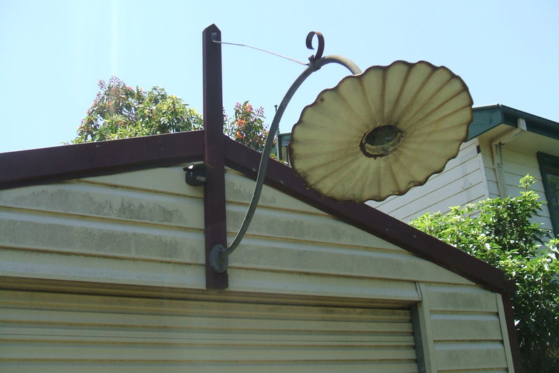
Vintage radial wave streelight is fitted with a 12V 40W B22 based
bulb. Bulb is clear, so not very visible in the photo. It is switched by
a PIR sensor modified for 12V.
Circuit Breakers
Naturally, with 100's of amps available
from the batteries, some sort of overload protection has to be provided.
I simply used 240V MCB's as I had them and the rating suited. While they
might be rated "AC only", the fact is that at 12V an arc cannot be maintained
across the contacts, so it is acceptable to use them this way. 240VDC would
be another story.
Separate light and power circuit breakers
are installed where the battery feed comes in under the house.
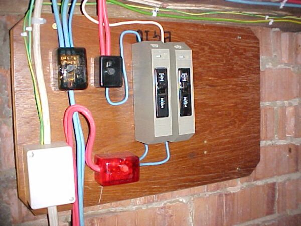
Light and power circuit breakers under the house. The paralleled
16mm conductors coming from below is the battery feed from the garage.
The start and finish of the power ring main is visible connected to the
links at the top. The right circuit breaker feeds the light circuit by
4mm wire. At the left is the 240V feed from an inverter located with the
batteries.
There is about 8m between the batteries and this point. To reduce voltage drop, two paralleled lengths of 16mm wire were used.
Batteries
I started off with four Yuasa 6V 90Ah
batteries giving 12V at 180Ah. Originally, these came from radio station
2WS, where they were part of a UPS. I don't know how old they were, but
they looked well used when I got them in early 1999. Initially they were
used in the garden shed, charged by a 22W panel and gave good service.
However, the increased demands from the house showed up their deterioration,
and in 2007 they were replaced with four 6V 232Ah batteries made by U.S.
Battery.
When these failed in 2017, they were replaced by three Narada 12NDF100 AGM batteries. These are 100Ah each. The batteries are located in the garage, and also feed light and power circuits there. I am aware that paralleling batteries is not the best way to increase current capacity, but the batteries were obtained at a good price. The reason is that if a cell shorts out in one battery, a high current will flow into that battery from the other good one(s). The correct way is to use larger 2V cells in series. If one shorts, the others are not affected. For the setup I have with three paralleled 12V batteries, each battery should have its own fuse, but it's one of those things I haven't worried too much about.
When deciding how much battery capacity to have, the charge input current has to be taken into account. The batteries will never full charge if their capacity is too great, relative to charge current. A good rule of thumb is that battery capacity is such that full charge is achieved by the middle of the day.
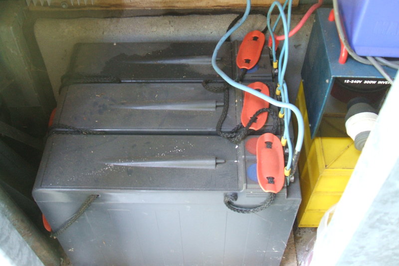
Three 100Ah batteries store the solar charge. Installed in 2017,
replaced in 2025.
In November 2025, the batteries were replaced with three Optraffic 6GFM120G batteries. These are 120Ah, giving a total of 360Ah.
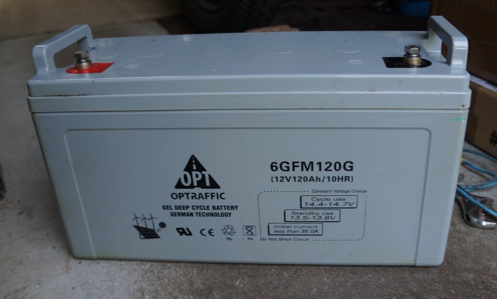
Latest batteries in use, installed November 2025.
Because lead-acid batteries are damaged if they are fully discharged, a mains powered back-up charger switches on when the battery voltage gets to 10.8V. This only happens after several cloudy days if high demands have been made on the batteries.
Regulating the charge
Solar panels provide a constant current
charge. This means that a controller is needed to ensure the batteries
do not overcharge once they are fully charged. My first charger was one
I designed and built. I used the comparators in a 555 to sense the battery
voltage and switching points, with the voltage reference determined by
a LED. An ammeter shows charge current. Of course, a diode is in
series with the solar panel input to prevent reverse current flowing at
night. A more detailed description of the charger is described
here.
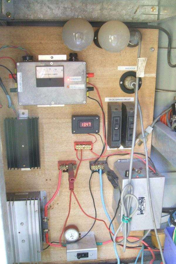
Garage switchboard contains the charge controller, regulator, and
mains charger. The two 200W light bulbs at the top control charge current
for the mains charger.
An auto-start 300W inverter feeds 240V AC to a power point inside the house. This is useful for operating low power mains appliances during a power failure.
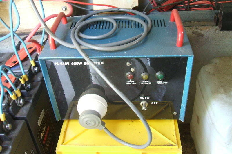
This inverter is based on a design from Electronics Australia, June
1981. It provides 240V to a power point in the house.
Voltage Regulation.
Because during charge, the batteries can
reach 14.4V, the supply to the house and garage is regulated. While some
loads tolerate 14.4V, some are stressed by the higher voltage. Hence, this
regulator was installed.
Voltage is regulated to 13V which allows
for some voltage drop in the wiring.
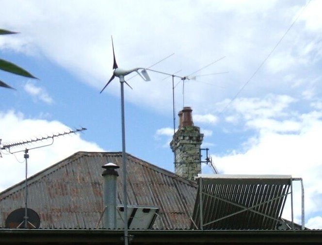
Air X facing north. Unfortunately, the location provided
poor output.
Later comments I'd seen on the Air X implied that they never fully charged the batteries. I was suspicious of the charge voltage being limited to 13.8V, although it is adjustable. Air X seem to have faded away, replaced by numerous cheaper Chinese look-alikes.
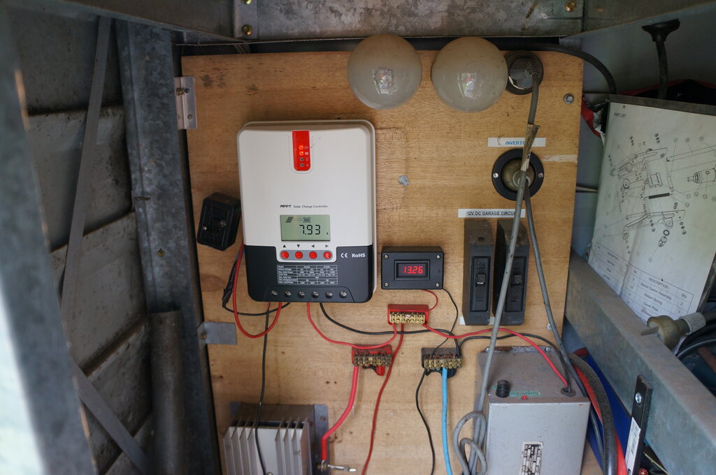
MPPT controller installed. It works well.
While the homemade charge controller worked
well, I upgraded it to a commercially made MPPT (Maximum Power Point Tracking)
type. The reason for so doing is greater efficiency. A solar panel is a
constant current source, with an open circuit voltage somewhat higher than
the battery it's designed to charge. 12V solar panels might have a typical
open circuit voltage of 18 or 20V. What this means in practice is that
you're not getting maximum power transfer, unless the battery voltage increased
to the solar panel's open circuit voltage. This obviously will never happen,
since a fully charged 12V battery, when cycle charged, is around 14.4V.
In recent years, the MPPT charger has
become popular. This contains a switchmode regulator to efficiently drop
the solar panel open circuit voltage to that of the battery. In other words,
the solar panel is operated under its most efficient condition, despite
the battery being of lower voltage. In simple terms, the solar panel 'sees'
the battery as being 18V, and maximum power transfer takes place. Also,
as the solar panel output varies during the day, the charger compensates
for this by loading the panel to whatever voltage will produce the most
power.
These controllers also have an equalisation
feature, which charges the battery up to 15V, say once a month. Because
the battery cells are all charged in series, there exists the possibility
of some cells receiving more or less charge, depending on the condition
of those cells, since the charge current is the same through all of them.
For example, some cells might get to 2.2V and others to 2.4V. Equalising
the cells involves applying a higher charge voltage for a short period.
A further feature, which I haven't used,
is an under voltage cutout, which disconnects the battery from the load,
should the voltage get too low. Drawing current from a lead acid battery
once the voltage has dropped to 1.8V per cell permanently damages it. Two
reasons I don't use this feature is because I have a mains standby charger,
and also the risk of completely losing power (e.g. for alarm clock) is
undesirable.
Another feature also allows for switching
on a load at night - obviously for a lighting set up. As with all these
microprocessor type controllers, various data is available from the display.
The controller senses temperature and adjusts charge voltage to suit, since
the optimum charge voltage is temperature dependent.
However, the most useful feature is that
you can use much higher voltage solar panels. Household panels used for
240V grid feed in are now very inexpensive second hand. Typically, these
are around 36V. With the MPPT charger, these can be used for a 12V system.
Indeed, I have three 36V 250W panels in
parallel feeding the 12V system in the shed.
The controller I use is one of many available on eBay. It works very well, except for one thing. It radiates a lot of RFI throughout part of the MW band. This is not surprising, given the switchmode controller, the current it is switching, and the length of the cable between the solar panels and the controller. Some attempts at filtering have helped, but more investigation needs to be done. At least at night there is no problem.
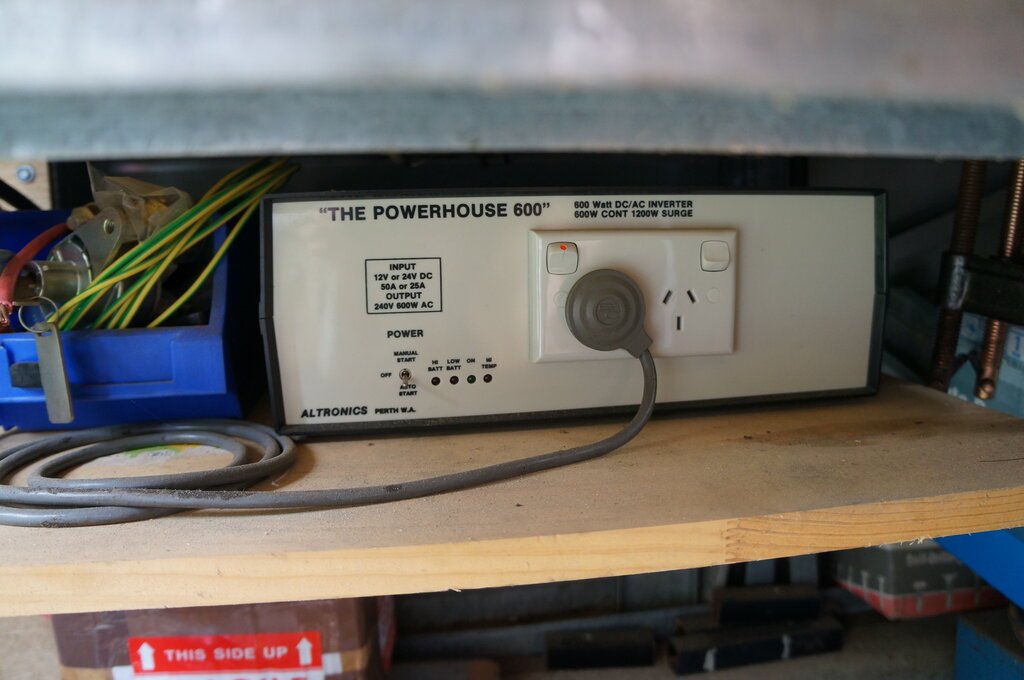
Inverter now 600W.
I've also changed the 300W inverter for a 600W type; this time an Altronics kit which I got at an HRSA auction.
First thing evident is that my choice of
wiring gauge paid off. Voltage drop is not a problem. In retrospect, I
should have used a thicker feed for the light circuit as there is a slight
dimming when more than one light is turned on. However, very rarely is
a light on in more than one room, and it's the change in brightness that
makes it obvious, not that the light is actually dim and unusable.
The solar panels work well. With the original
set up with only 120W of panels, I had a fan pulling 7A all day and still
had plenty of charge left that night. In fact one can be a little careless
about leaving lights on.
And the wind generator? Well, to be honest,
it was useless where it was. Being so close to the house resulted in it
turning out of the wind when it picked up speed. It would have to be moved
further away and raised higher. Even so, the solar panels provide sufficient
current and the wind generator isn't really needed. With the abundance
of sun where I live, I would not even consider a wind generator again.
I definitely recommend AGM batteries. These have not only lasted longer than wet lead acid types, but they are maintenance free, and the problem of acid all over the terminals and the surface of the batteries is largely eliminated. Since I first built this system, Li-Ion batteries have become firmly entrenched in alternative energy systems. It is possible I will use them for future replacements, provided the cost comes down to that of AGM types, and something can be done about the fire risk.
The key things in an alternative energy
system are; 1) suitable wiring thickness, 2) more charge capacity than
needed, 3) more battery capacity than needed, and, 4) lights and
appliances as good as their mains counterparts.
As for the typical solar panel and car
battery bodge with speaker flex and car bulbs, forget it!