In a solar electrical system, the battery
voltage is constantly varying. At night with low charge, the batteries
might get down to 11V. In the day time with the batteries coming up to
full charge, the voltage might get up to 14.4V.
While this is all normal for the batteries,
a problem arises in that any loads connected to the batteries will see
this excess voltage when the batteries are charging. It is of course problematic
only during the day time and loads are in use.
This project was prompted by finding an
inverter too hot to touch after it had been running all afternoon on a
sunny day. While many 12V appliances will tolerate up to 13.8V, 14.4V is
pushing the limit too far. Valve equipment and vibrator inverters should,
in any case, be run at closer to 12V.
What was needed was a regulator between the batteries and house feed, to limit the maximum voltage the loads would see. Allowing for voltage drop in the wiring, it was decided that 13V would be the optimum limit.
Initial ideas centred on a voltage sensitive
relay, that when the voltage became excessive, would switch in some high
current diodes in series with the house feed. The idea of course is that
silicon diodes have a defined voltage drop of about 700mV, depending on
current. So, when the battery voltage rose to 14.4V, two diode drops would
restore this to 13V.
However, the limitation with this scheme
was there was no regulation as such. That is to say, the voltage could
be at 14.2V for several hours, and the loads would be exposed to this,
because this is below the switching threshold.
Conversely, if the diodes were switched in, the load voltage could be excessively low before the relay switched them out again. In short, this concept was not suited to a slowly rising and falling supply voltage.
High Current Mosfet.
What was needed was a conventional linear
regulator. A challenge in a 12V solar electrical system is that voltage
drop must be minimised between the batteries and the loads. While at 14.4V,
some voltage drop is obviously desirable, the problem is when the batteries
are not being charged, and have fallen to, say, 12V. The regulator must
now be invisible, because any voltage lost across it will now be very obvious.
Essentially, we need a regulator with
an extremely low saturation voltage. Furthermore, the current rating needs
to be very high as it's supplying the entire house. In my system, there
are two 15A power circuits and two 15A light circuits. So, before the breakers
trip, we have to allow for 60A.
This kind of current is too much for conventional
power transistors, especially if virtually no saturation voltage is to
be obtained.
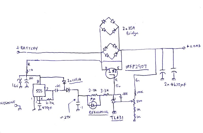
The answer is to use a power Mosfet. These have extremely low on resistances, and these days, very high current types are available; commonly used for motor speed control and such applications. After a bit of searching on eBay, I found type IRFP2907. With only 4.5 milliohms when saturated, this would be perfect. In fact, it would probably have less voltage drop than a mechanical switch! The maximum voltage is 75V, which in a 14.4V system gives a huge leeway in terms of the possibility of it breaking down. Most importantly was a current rating of 209A!
It would appear that in normal use, this Mosfet would be indestructable, even if all four circuits were short circuited, and before the breakers tripped.
The circuit is loosely based on one I happened to see on the internet. A Mosfet actually makes a very good linear regulator, despite them seldom being used for this purpose. They are easy to drive due to the high resistance gate, and as mentioned previously, have an extremely low saturation voltage.
The circuit here operates the Mosfet as
a source follower. This is equivalent to an emitter follower in the bipolar
transistor world. However, the gate voltage needs to be higher than the
source voltage by at least a few volts for saturation to occur. Therefore,
the gate supply has to be higher than the supply input voltage.
Here, a 555 in astable mode oscillates
at a high frequency, and with a half wave voltage doubler, something approaching
twice the supply voltage is obtained across the .1uF filter condenser.
Regulation is achieved by a TL431 which functions as an adjustable shunt regulator. A portion of the output voltage is fed into the reference terminal of the TL431, and if the output voltage exceeds 13V, the cathode voltage is pulled down, reducing the Mosfet's gate voltage, and thus its drain voltage. In this regard, the circuit performs in a perfectly normal way.
In series with the 29V supply to the TL431 load resistor, is a LED to show if the circuit is regulating. While ever the TL431 draws current, the circuit is regulating, and thus current flows through the LED. When battery voltage drops below 13V, the TL431 is no longer conducting, the LED no longer illuminates, and full gate voltage is applied to the Mosfet, saturating it. The voltage drop across the regulator circuit is now insignificant. With 5A flowing, about 50mV drop was measured.
The 555 oscillator is protected against high voltage by means of a 15V zener diode and 10R resistor. It's possible with inductive loads on the system for high voltage spikes to be present. Also is the possibility of the battery being disconnected or going open circuit. In this situation, the regulator would be exposed to up to the full open circuit voltage of the solar panels. This will be in excess of the 18V maximum suppy voltage for the 555.
A fail safe circuit is also provided. This
is the purpose of the two 35A bridge rectifiers. If a fault in the regulator
failed prevents the Mosfet conducting, the house would lose supply. The
rectifiers are connected so each pair of diodes are in series, allowing
for a 1.5V drop. In theory, with four pairs of diodes, the total current
carrying capacity should be 120A. Again, this is much higher than necessary.
If the Mosfet fails to conduct, the house
voltage will fall to 1.5V below the battery voltage; i.e., 10.5V when the
batteries are not being charged. This is sufficient to prevent having to
reset clocks, etc., and lights will still function to a useable degree.
Of course, having this permanent 1.5V
maximum voltage drop across the Mosfet, it means that when the circuit
is regulating normally, should the battery voltage rise above 14.5V, then
so the house supply will start rising above 13V. However, this will only
come about if the solar panel charge regulator fails.
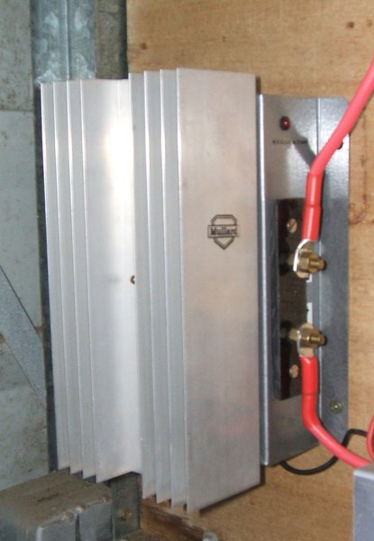
The regulator was built on a chassis made
of zinc sheet. The largest heatsink I could find accomodated the bridge
rectifiers and Mosfet. Normally, the heatsink runs barely warm. The continuous
drain of my 12V system is about 2A, so with about 1.5V dropped, that equates
to 3W. It should also be pointed out that even under high loading, the
heatsink still won't run very warm. With a 10A load, and the supply at
14.5V, that's only 15W of dissipation.
My solar panels are limited to about 20A
charge current, so under very high load, the voltage will fall below 14.5V
anyway, again reducing dissipation in the Mosfet. In larger systems, some
thought would need to be given to the maximum loads used, and the maximum
charge current available.