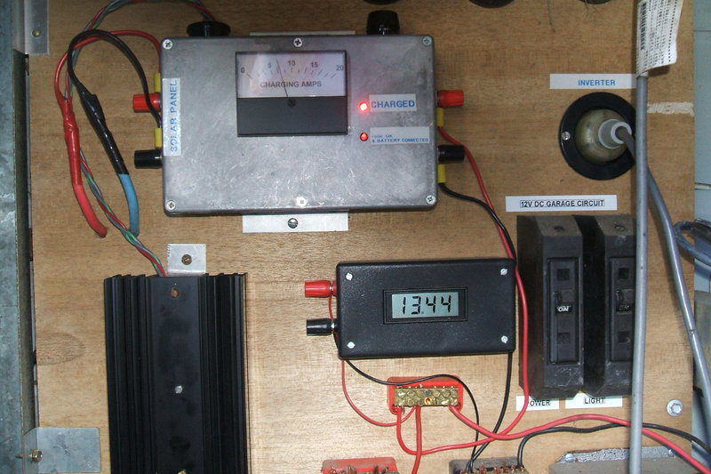
Charge controller with ammeter at top. Under left is the Mosfet heatsink. At right is the battery voltmeter.
Charge controller with ammeter at top. Under left is the Mosfet
heatsink. At right is the battery voltmeter.
This charge controller started life when
I first implemented my 12V
solar electrical system.
It was initially a simple voltage switch
type of regulator. That is, the solar panels feed the batteries directly
until the battery voltage reaches a preset level; usually around 14V. At
this point, a relay disconnected the solar panels, preventing any further
voltage rise (and thus overcharge). Of course, the voltage would start
to fall again, and at a lower preset voltage, around 13V, the relay would
connect again. The charger would cycle continuously like this while ever
the panel voltage reached 14V.
However, learning about the charge requirements of deep cycle batteries indicated this wasn't really the best way to charge them. I got nine years out of my first set of new batteries, which is pretty good, considering the simplicity of the charger. Now, on the next lot of batteries which are sealed AGM types, I was prompted to make improvements. The previous flooded lead acid batteries could tolerate overcharge better, in that distilled water would need to be added every so often. Sealed lead acid types are less tolerant (and more expensive).
The preferred way to charge is to first charge up to the cycle voltage (14.3V) and then maintain a float voltage (13.5V). With the charger in its original form, the fact that it kept cycling to 14.3V even after this voltage had initially been reached, suggests overcharging may have been occurring.
Aside from that, the charger worked very well in that the voltage sense circuit was reliable and accurate, and no reliability problems occurred except for the fuse holder being inadequate. This was a 3AG type but the constant 20A was too much, and fuses failed frequently from overheating contacts. A 5AG type was substituted which solved that problem.
It seemed the existing regulator could be used, just by adding a simple linear regulator to achieve the float function. As the float voltage is higher than the switch on voltage (13V), the charger would automatically stay in float mode once full charge had been reached. This proved to be correct, and the resulting design worked perfectly.
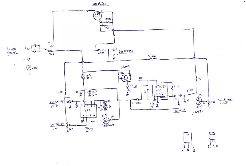
The charger comprises two sections. 1)
the voltage sensitive switch, and 2) the float regulator.
The voltage sensitive switch.
The solar panel connects to the battery
via a cutout diode, and the normally closed contacts of the relay. A 20A
ammeter completes the circuit, and a 20A fuse provides protection in case
of a wiring short circuit. At this point, current flows from the solar
panels into the battery, provided of course the panel voltage is higher
than the battery. The battery voltage begins to rise.
A voltage sensitive switch is based around
the comparators in a 555 IC. The voltage reference is two series connected
LED's connected to pin 5. This provides 3.6V.
When the input to pin 2 falls below half
the reference voltage (1.8V), pin 3 goes high. When the input to pin 6
rises above the reference voltage, pin 3 goes low.
By means of two 10K trimpots, the inputs at pins 2 and 6 can be adjusted to cause switching to occur at the required battery voltages. Assume the battery is at 12V. This is below the 13V switch on threshold. Pin 3 is thus high. Because the relay driver transistor is a PNP type, no base current flows. The Charge LED is not illuminated, and the relay coil is not actuated. Current from the panel flows through the N.C. relay contacts, and the battery charges.
When the battery reaches 14.3V, pin 6 reaches the 3.6V reference voltage. Pin 3 goes low. Current now flows from the base of the BD140 transistor, through the 1K, and the Charge LED, into pin 3 of the 555. The Charge LED lights, and the relay coil is activated. This disconnects the panel from the battery, stopping further charging.
The battery voltage starts to fall, and soon the voltage at pin 2 reaches 1.8V. This makes pin 3 go high again and the relay switches off, reconnecting the panel to the battery. Once again, charging recommences.
The supply to the 555 at pin 8 is protected by a 15V 5W zener diode in case the battery is open circuit or not connected. Under this condition, full open circuit voltage from the solar panel is available, which exceeds the 555 rating. The open circuit voltage of the panel can be over 20V. Should the zener conduct, a small light bulb limits the current. It's a small 12V type with a cold resistance of 12 ohms. The advantage of using a light bulb is that as the input voltage rises, the current will automatically self regulate to a degree. The 555 and relay circuit is powered from the battery at all times.
The relay is a SPDT 30A horn relay. The cutout diodes are a large dual Schottky type as used in switch mode power supplies. This drops less voltage than a silicon type, and runs cooler as a result. It means more power goes into the battery and less is turned into heat. The trimpots are multi-turn types. The setting is critical. An improvement could be made by using lower value types; e.g.. 500R with appropriate resistors in series with the ends of the elements, to centre the optimum settings. Note that the trimpots are fed from after the fuse to obtain a more accurate measurement of the battery voltage (the fuse drops some voltage, dependent on current).
Float Voltage Regulator.
Up to this point, the charger works as
a normal voltage sensitive switch type, and can be used as such if the
limitations of this method of charging are taken into account.
With the addition of some extra circuitry
to the original charger, it is possible to include float charging.
As before, when a discharged battery is
fed current from the solar panel, its voltage rises. Again, when the 14.3V
threshold is reached, the relay is actuated. The solar panel now connects
to the N.O contacts, which feed the battery via a Mosfet. The Mosfet is
operated in its linear mode as a voltage regulator, whose output is set
to the float voltage (13.5V).
This part of the circuit has a lot in
common with the
house regulator, and uses the same Mosfet; a type IRFP2907.
Because the Mosfet gate voltage needs
to be higher than the supply, a 555 operates as an oscillator and by means
of a half wave voltage doubler, provides about twice the supply voltage
at the .1uF filter condenser. This voltage feeds a TL431 adjustable reference
via a 3.3K resistor. A sample of the battery voltage is fed into the reference
pin via a 5K multi-turn pot. The cathode of the TL431 feeds the Mosfet
gate, and the source voltage becomes a few volts less than this. If the
battery voltage rises above 13.5V, the cathode voltage of the TL431 falls,
reducing the Mosfet gate voltage, and thus thus the drain voltage.
The Mosfet must be mounted on a reasonably
large heatsink.
The battery is now maintained at 13.5V indefinitely, as long as the panel voltage remains above 13.5V. This it will do as long as the sun is shining, and the panel charge current is greater than that drawn by the loads running off the system. Because the battery is held at 13.5V, the 13V threshold is not activated and the charger does not cycle.
At the end of the day when the sun stops shining, the battery voltage will start to fall. The Mosfet will saturate minimising any charge loss. Eventually, the 13V threshold will be reached, and the relay will reconnect the N.C contacts, until the next day when the batteries reach 14.3V again.
Over voltage protection is provided for the second 555. The existing 15V 5W zener diode is used by means of a 1N4004 diode. If pin 8 should rise to above 15V, the 1N4004 will conduct and its cathode voltage will be limited by the zener. Current limiting is by a 10R resistor. Note that the 2nd 555 operates only when the relay coil is actuated. This saves a small amount of power. Because the battery voltage is now regulated, so is the 555 supply, not that it really needs to be. However, it was found that with an unregulated supply the frequency of the 555 varies, which can cause RFI. This was found with the initial design of the house regulator and was problematic, until the 555 was fed from the regulated supply.
Note that the cycle and float voltages specified are those recommended for my batteries and may differ for other types.