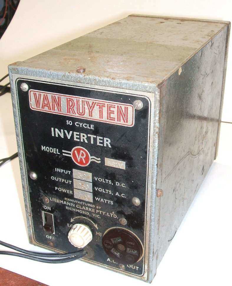
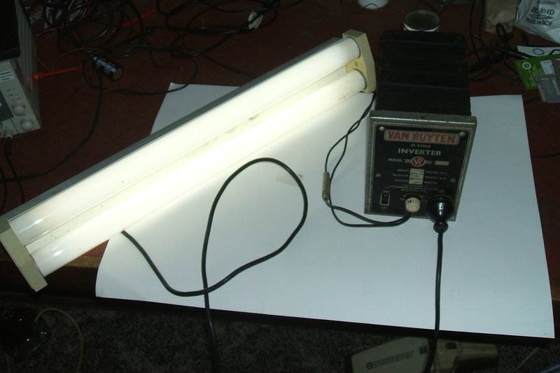
This inverter came to me for repair from a fellow HRSA member who is an enthusiast for 32V lighting plants and their accessories. Previously, I had repaired this AWA solid state inverter for him. The Van Ruyten vibrator inverters were popular, and a 12V 100W model in my collection is described here.
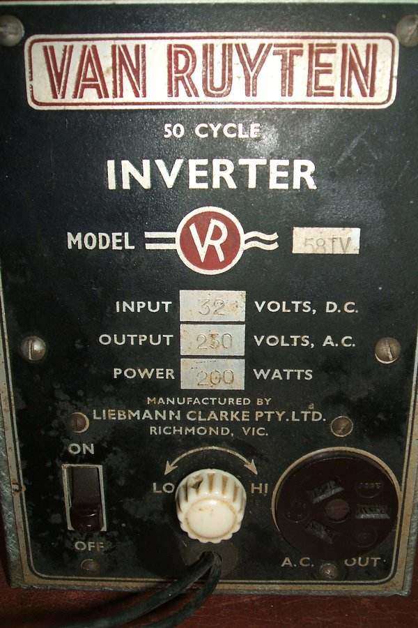
The 58TV is a 32V model, with an output of 230V 50c/s at 200W. The power rating and the "TV" designation in the model number perhaps suggests the inverter was intended to power television receivers. 230V was the standard mains supply in Victoria where this inverter was manufactured. There were many areas outside the cities reliant on 32V lighting plants which could receive TV signals, so there was a market for 32V television sets, and inverters to operate conventional 240V sets. Ferris manufactured 32V sets, but for other brands, an inverter had to be used.
This 58TV was obviously well used. Along
with it came a box containing three extra vibrators and the suggestion
that some were faulty or unknown in condition.
Two 100W transformers are connected in
series to obtain the 200W rating. This is a better method than connecting
transformers in parallel because series connection will guarantee equal
current sharing in the windings. Needless to say, the inverter is rather
heavy!
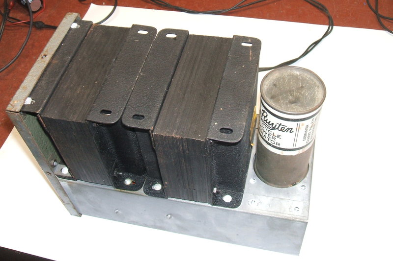
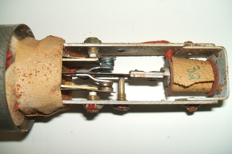
Above chassis has only the transformers and vibrator visible.
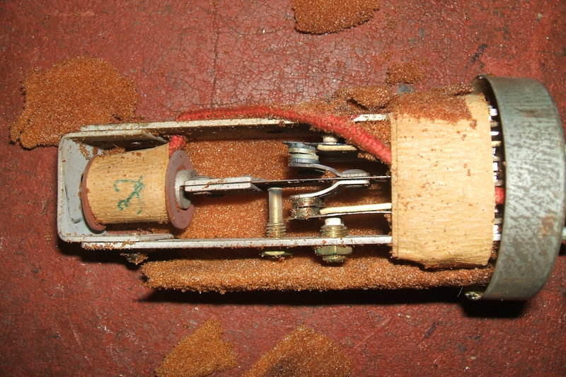
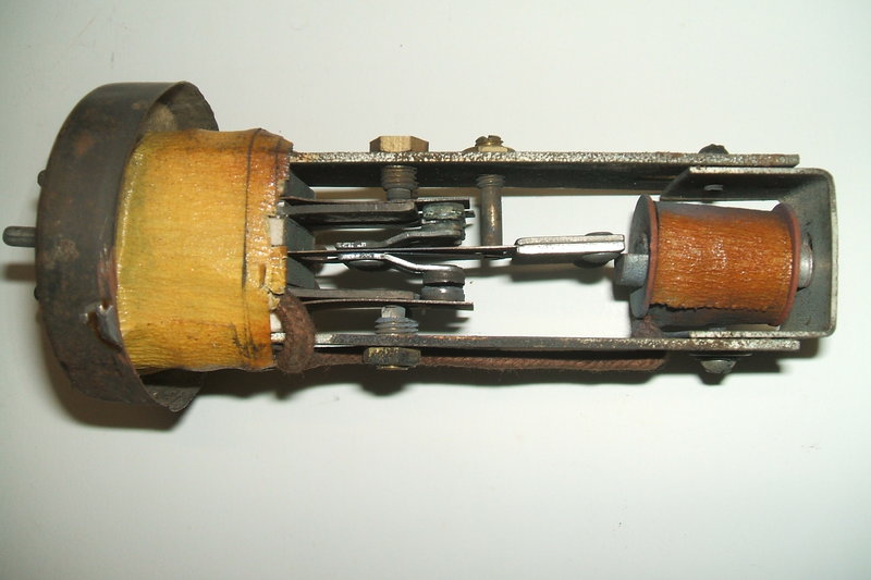
As per the 12V model, a large UX-5 based vibrator is used, which appears to be of ATR (American Radio & Television) design. The vibrator is identical to the 12V type except for the drive coil. It is a dual-interrupter type with two sets of primary switching contacts connected in parallel inside the vibrator. The vibrator is a series drive type with a separate contact for the drive coil. The vibrator is labelled as being made by Liebmann Clarke Pty. Ltd. in Richmond, Victoria. It has no type number, except for the voltage rating.
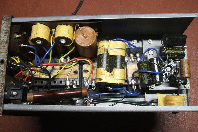
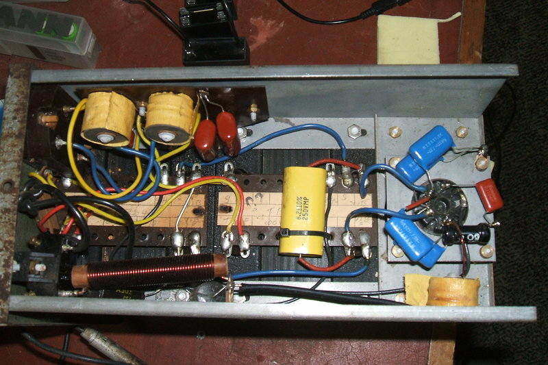
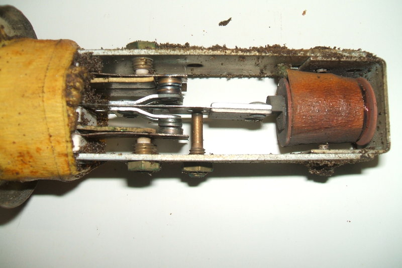
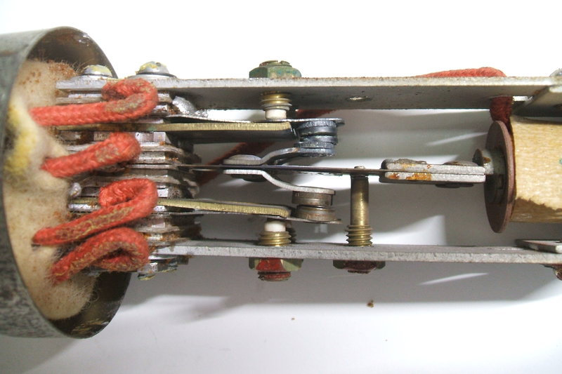
Under the chassis with original components.
Transformers.
The most unusual thing perhaps is the
two series connected transformers. These are both Trimax type TP3640, rated
at 100W for 50 cycles.
It is unclear if there is a 100W model
using just one TP3640. Are these just 32V transformers connected in series?
Given that the primary voltage is halved when two are in series, the secondary
voltage would also be halved (i.e. 115V). But, because the secondaries
are in series, the final output is 230V. Or are they actually 16V transformers
with 115V secondaries? Either way the circuit would work, but it's possible
the regulation would be poorer if they were 32V types - this being because
the turns per volt ratio would be more than optimum. One could test the
transformers individually at both voltages - if they saturated at 32V,
it would indicate they were most likely 16V types.
Conveniently, the terminals for the transformers
are labelled which made tracing the circuit relatively easy. The
start, finish, tapping, and shield connections are all identified.
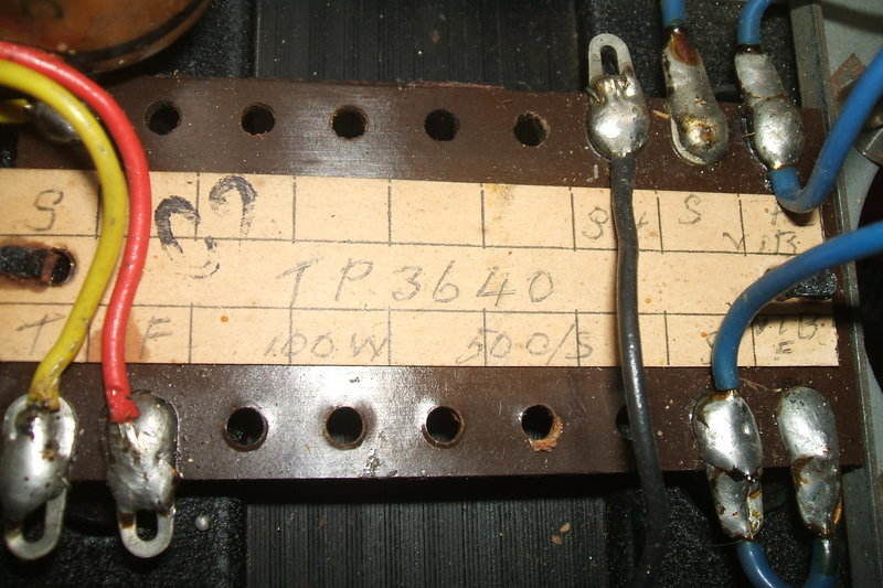
Transformer connections are clearly labelled.
In view of the power rating, a high - low switch is provided which selects the full secondary, or a tapping thereof. This is necessary because regulation is not perfect, and also to allow for variations in the supply voltage.
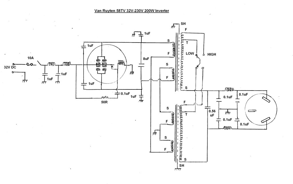
Output Circuit.
This consists of a secondary buffer (0.56uF
600V) and a balanced pi-filter with two chokes and four 0.1uF condensers.
These condensers also add an extra 0.1uF to the secondary buffer. The earth
pin on the output socket was not connected to anything.
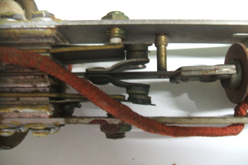
Primary Circuit.
This is quite conventional for this kind
of circuit. The vibrator reed is fed with 32V and this switches alternately
to either side of the transformer primary. The centre-tap is earthed. This
is the reverse of car radio practice where the C.T. is the supply, and
the vibrator contacts switch either side of the primary to earth.
The main timing capacitance is 8uF, which
consists of four parallel 2uF capacitors. For inverters operating above
12V, it becomes practical to have most or all of the timing capacitance
across the primary, which is electrically the best place for it. Additionally,
there are four 1uF capacitors; two from either side of the primary to earth,
and two across the vibrator contacts. These latter four are for RFI and
spark suppression, but will also add to the primary buffer capacitance.
The vibrator drive coil contact also requires
a spark suppression circuit. This consists of a 0.1uF and 50R across the
contacts. The 50R limits the capacitor discharge current when the contact
closes. Oak radio vibrators, although series drive, do not require this
circuit as they use a patented short circuited secondary winding on the
drive coil, which slows the rate of flux collapse when the contact opens.
Input filtering for the 32V DC supply is
provided by two chokes and a pair of 1uF condensers. A normal domestic
tumbler switch turns the inverter on or off. An inline 10A fuse provides
protection from overload.
As the inverter uses a non synchronous
vibrator, and there are no polarised components, it does not matter which
way round the inverter is connected to the 32V supply, except for the matter
of earthing. One side of the supply connects to the inverter chassis and
case, and this should be the earthy side of the supply for best RFI suppression
and to prevent short circuits.
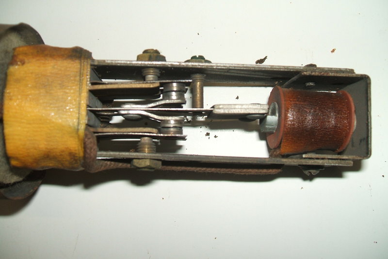
New capacitors installed.
The primary timing capacitcance was a bundle
of four parallel connected 2uF AEE Microcaps rated at 300V. I replaced
this with a single 8.2uF polypropylene 250V type. This was an expensive
capacitor, but is ideally suited to the pulse current it has to carry,
as well as being neater than four individual capacitors. The rest of the
capacitors were replaced with ordinary polyester types.
Experience has taught me that the choice
of timing capacitance is not always as good as it should be in the case
of DC-AC inverters, so before simply replacing the 0.56uF secondary capacitor
with the same, I checked the waveform.
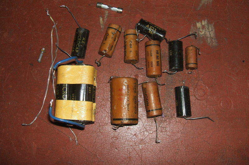
Unreliable leaky paper capacitors and a blown fuse were replaced.
Out of the four vibrators supplied, one looked reasonable enough for testing without repair. At this point I was curious to see what the waveform would be. This was observed across the primary timing condenser, since this is what the vibrator contacts see. Tests were done with no load, a 100W incandescent bulb (resistive load), and a 40W fluorescent lamp with no phase correction (low power factor inductive load).
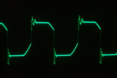
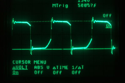
No load waveform. The short slope indicates excess timing capacitance.
As mentioned in the other DC-AC inverter articles on this site, buffer (timing) capacitance for a general purpose inverter is difficult to choose, and usually ends up being a compromise. The problem is that the load may be capacitive, resistive, inductive, or only draw current at the voltage peaks. This variation in load affects how the timing capacitance works, which subsequently determines the timing of current flow vs. when the vibrator contacts close and open. And, this ultimately determines vibrator life.
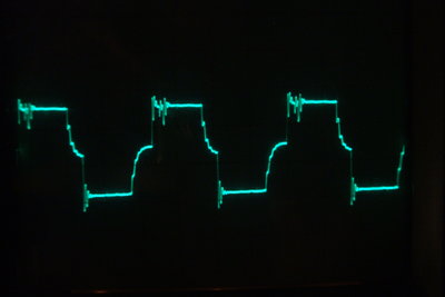
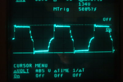
Loaded by a 100W incandescent bulb, the waveform is as expected
with the buffer capacitance now appearing to be inadequate. Contact bounce
is visible - the contacts had not been cleaned at this stage.
If the load is resistive, as in the case
of an incandescent light bulb, the timing capacitance is effectively reduced
because current in the load, and thus the primary circuit, is always flowing,
and the timing capacitance is discharged faster than normal.
The loading prevents destructive overshoot,
so transformer insulation is not at risk, and excessive contact sparking
does not occur. However, because the timing circuit is no longer operative,
the vibrator contacts are carrying more current than the ideal situation
at the point of closing and opening. With an ideal timing circuit, current
flows only after the contacts have closed, and stops just before they open.
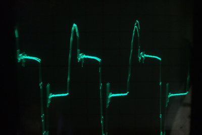
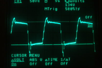
With a low power fluorescent lamp, the buffer capacitance was clearly
inadequate with undesirable overshoot appearing.
If the load is inductive, as with a fluorescent
lamp which is not power factor corrected, or an induction motor, the timing
capacitance is cancelled out to some degree, and destructive overshoot
appears on the waveform, as does arcing at the vibrator contacts. This
is shown here quite clearly.
Purely capacitive loads are unlikely to
be used with an inverter of this kind. The only common instance with domestic
appliances is where a capacitor is used as a voltage dropper. The effect
of using a capacitive load is that the timing capacitance is increased,
with an increase in primary current.
Inadequate timing capacitance is much more damaging than too much, so given the range of loads the inverter may be used with, the compromise is to provide just enough capacitance for the inductive loads likely to be used. This unfortunately results in an increase in current consumption with other loads, and is particularly evident with no load, or very low loading. Higher loads tend to swamp this out. Therefore, an inverter like this should not be used for small loads to obtain best efficiency.
I thought it worthwhile to connect the output socket earth pin to the chassis. Even though it is not required for safety since the output is balanced, it's a good idea to improve RFI suppression, where the equipment powered is fed with a three core cable.
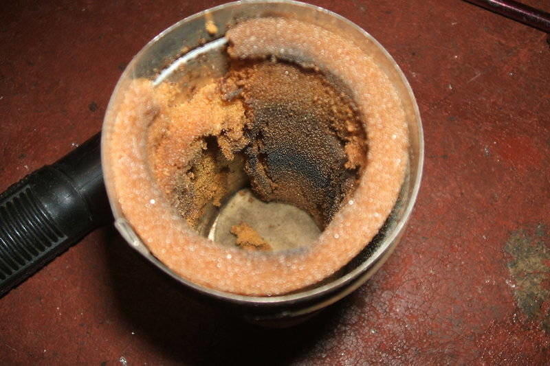
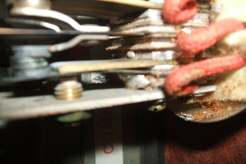
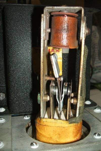
Decomposed acoustic insulation.
Foam rubber crumbling apart. Note the misalignment of the upper
set of contacts.
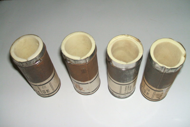
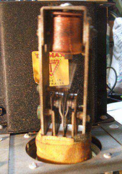
Cans re-lined with modern foam rubber.
Restoring the vibrators was the most time consuming part of the job. Some of them had the contacts in obvious misalignment, as well as being badly damaged. One vibrator had short circuited contacts. Then was the matter of contact timing. Not only do the contacts have to be set for the right duty cycle, but also both sets of contacts have to be timed to make contact simultaneously. It was determined that the VR vibrators operate with a 70% duty cycle. Effectively, this means an on time for each contact of 7ms, and an off time of 3ms.
Vibrator 1.
The first vibrator was in reasonable condition and just needed a physical clean. Both contacts have a 6.9ms duty cycle.
Vibrator 2.
Likewise, the second vibrator needed cleaning. It has a duty cycle of 7.1ms on one side and 7.4ms on the other.
Vibrator 3.
The third vibrator was in very poor condition.
I noticed while connected to the test
panel that vibration seemed restricted and one set of power contacts
were sparking - even though nothing was connected to them!
Note the upper contacts - the tungsten contact has been welded off
centre on the lower side contact arm. The lower contacts are also misaligned.
Looking at the other set of contacts, the excessive misalignment
is obvious on the lower set. They were actually touching!
A lump of solder was shorting between the frame and one set of power
contacts. It was quite difficult to remove. A smaller lump of solder is
visible on the adjacent side towards the centre.
The strange performance turned out the be a lump of solder stuck between the frame and one of the power contacts, effectively turning the vibrator into a shunt drive type, which it was not designed to perform as. Once this was removed, normal vibration was returned. Next, the stack bolts had to be loosened and the contacts re-aligned. One of the tungsten contacts had been welded off centre to its support arm. Nothing could be done about this, but the corresponding contact had enough adjustment to be aligned with it. Once all that was done, the contacts were cleaned and the duty cycle adjusted. It turned out well with an equal 7ms per contact duty cycle. However, once reinstalled in the can, vibration seemed weak. This was because the reed starting voltage was too low. The adjustment for the reed contact is a compromise between starting voltage and sufficiently vigorous vibration. It is pointless having the reed start vibrating at say 10V when there is no way the inverter would be used on such a low voltage. A starting voltage of about 20 gives sufficient vibration with the can in place.
Vibrator 4.
Severely burned contact indicates incorrect operating conditions.

Part of the contact has eroded away.
The fourth vibrator had the worst contact damage. All I could do is clean it up as best as possible. Duty cycle was 7.4ms and 7.2ms.
Despite vibrators 3 and 4 being badly damaged, they did restore OK and performance is good. The question of how these vibrators were assembled has me intrigued. There is no way the contacts could have moved out of adjustment like they had - they had clearly been used like that for the previous life of these vibrators - the wear marks make this obvious. My guess is that whoever assembled them found their job boring and just didn't care. Human nature being what it is - just imagine a bored apprentice assembling vibrators all day. The fact is the vibrator will work misaligned, but will just have a short life. And as long as any lumps of solder aren't actually touching anything at the time of testing, the vibrator is sealed up and sent out. I have never seen such poor quality control in vibrator assembly, except with some Ferrocart types. And, if I am not mistaken, it does appear that the Van Ruyten and Ferrocart vibrators were assembled by the same company; i.e. Radio Corporation. Luckily, the VR vibrator is of good design, and if set up properly there should be no problems with it. Unfortunately, the result of careless manufacture only provides negative comments about vibrator reliability from the naysayers.
There is also always the problem of unsuitable loads being plugged into an inverter. This probably causes more vibrator damage than anything else. Many treat the output socket of an inverter as though it was a domestic power point, with the ability to supply 10A and with no concern for power factor.
As can be seen, a perfect duty cycle was not obtained for all of the vibrators. Because of the time consuming nature of adjustment, the labour cost would start to become uneconomic for the owner, if perfection was to be obtained. Nevertheless, the outcome was acceptable.
High speed photography shows the vibrator in action at the instant
when contact is made. The human eye sees operation as shown at right.
As mentioned previously, these vibrators are dual-interrupter types. So, how does one adjust each set so they close and open at the same time as each other? In the case of vibrators with separate connections to each contact, such as the Oak dual- interrupter types, one can use an oscilloscope. But, with the VR type this is not possible. My method is to adjust one set of contacts for correct operation, and then bring in the adjustment of the parallel contacts so they spark at the same time as the first set. To get the spark, the contacts are connected across the output of a 30V 2A current limited power supply and the reed moved by hand. It isn't terribly scientific, but it must be remembered that over the life of the vibrator it is impossible to retain perfect adjustment anyway. This is why the current rating of such vibrators is simply not just the double of one set of contacts; the rating is somewhat less.
I used a double 20W fluorescent lamp for the tests. This is electrically the same as a single 40W lamp in terms of current and power factor, since the two tubes are operated in series with a 40W choke.
Double 20W fluorescent lamp provides an inductive load for testing.
It was found that 2uF of timing capacitance
gave a very good waveform, and the inverter operated with good efficiency,
but on no load the current draw at 32V was more than desirable. 1.5uF was
an improvement for no load operation, and still acceptable. Better still
was 1uF. There is some overshoot, but not of a destructive level, and vibrator
sparking is not problematic. A desk fan also provided acceptable operation
with this value. On that basis, two parallel 0.47uF 630V polyester types
were substituted for the original 0.56uF. It was decided not use an X2
type 250V AC capacitor as the value of these tends to decrease over time
when connected across AC.
It is still preferable that fluorescent
lamps be fitted with a phase correcting condenser where possible. Certainly,
this is important if fluorescent lamps of more than 40W are used. This
of course is not applicable to fluorescent lamps with an electronic ballast,
as these do not present an inductive load.
| Buffer | 0.56uF | 2uF | 1uF |
| No load input | 600mA | 1.2A | 800mA |
| 40W fluorescent (LPF) | 3A | 1.5A | 1.7A |
| 100W incandescent | 3.2A | 3.4A | 3.4A |
No load with 1uF buffer. Slope is noticeably short which indicates
excess capacitance.
100W lamp load with 1uF buffer. Ringing is due to transformer leakage
inductance.
40W fluorescent lamp (LPF) with 1uF buffer. Capacitance is less
than ideal, but not low enough to cause vibrator sparking.

Van Ruyten operating an AWA D65 television set. Current draw at
32V is 5.2A.
For valve television use, the Van Ruyten, or any other vibrator inverter is not ideal, because of the output waveform having a reduced peak to peak voltage. The B+ supply is determined by the peak supply voltage. In the case of the 240V AC mains supply, this being sinusoidal provides a peak voltage of 340. A 240Vrms square wave however provides a peak of only 240V. The output of a typical vibrator inverter has a peak voltage somewhere in between these values. With the inverter running an AWA D65 TV set, the output was 230Vrms with a peak of 260V. The AWA D65 is a typical mid 1960's valve set with a solid state voltage doubling rectifier power supply.
Had the 230Vrms been a sine wave, the peak
would be 322V. Effectively, the B+ rail voltage is reduced by 20%.
(There were some vibrator inverters made
in the U.S. by Electronic Laboratories and Cornell Dubilier Electronics
which did provide a sine wave output).
The set worked quite well, but a slight
lack of picture width due to the lower B+ supply was evident. It is quite
possible that there is enough internal adjustment in the set to compensate
for this, but this was not investigated. Pleasingly, there was no beat
pattern evident in the picture because of the 50 cycle output of the Van
Ruyten. This is in contrast to the solid
state AWA inverter with its 60 cycle output.
| Load | Input Current @ 32V | Output (Low) | Output (High) |
| 15W | 1.1A | 253V | 291V |
| 60W | 2.2A | 230V | 260V |
| 100W | 3.2A | 212V | 238V |
| 150W | 5.3A | 205V | 226V |
| 200W | 6.9A | 191V | 208V |
| AWA TV set | 5.2A | not measured | 230V |
A range of loads were measured to determine efficiency and regulation. Except for the TV set, these were incandescent lamps. The output rms voltage was measured with the output switch in both high and low positions. Input was maintained at 32V at the supply cable. Considering the simplicity of the inverter, regulation is quite good. As is typical, efficiency is greater with higher powered loads.
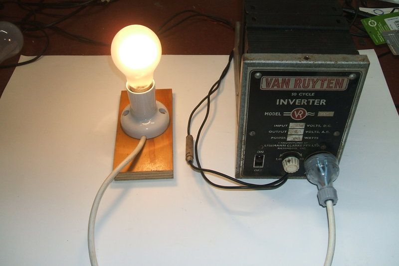
100W incandescent lamp is an ideal load.
In summary, provided the user is aware of the limitations, the Van Ruyten 58TV works very well, and as long as suitable loads are used, and excessive input voltages are avoided, vibrator life should be very long.