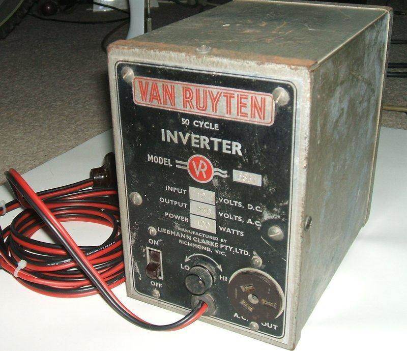
This inverter is another example of the
few Australian made high power 50 cycle types that existed in the pre-solid
state era. The origin of the name Van Ruyten appears to be from a 1930's
trademark of Tilbury & Lewis, a radio manufacturer in Richmond, a suburb
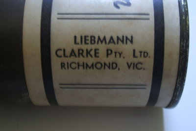
of Melbourne. At some point the name was used by Liebmann Clarke Pty. Ltd,
also of Richmond. Whether or not the premises were the same is not known.
I have seen a more recent vibrator inverter
than this one, of Liebmann Clarke manufacture, but without the Van Ruyten
name. It does appear that as time went on Van Ruyten specialised more in
inverters and less in radio.
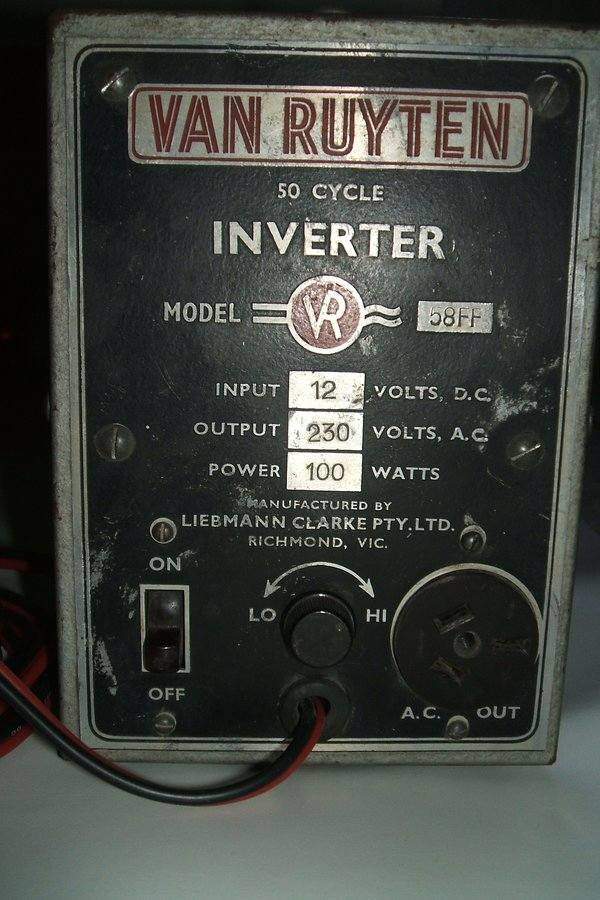
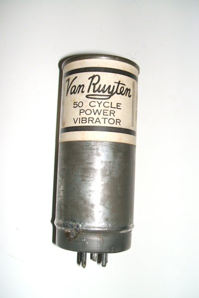
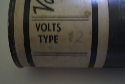
Made in Victoria, the output is 230V, not the later Australia wide standard of 240V. For its output power of 100W, this inverter is surprisingly compact. Most of the size and weight is due to the transformer.
I have not been able to put a year on its manufacture, however it does use polyester condensers everywhere except for the timing (buffer) capacitor. The smaller values are the Philips type introduced in the early 1960's, and the larger ones are a PCB mounted type, known as "greencaps". They look like they're late 1960's / early 1970's, and appear to be of Japanese origin. The wiring is all modern PVC. It would certainly appear to be of the last generation of vibrator inverter. There is a "473" on the paper timing capacitor which could mean April 1973.
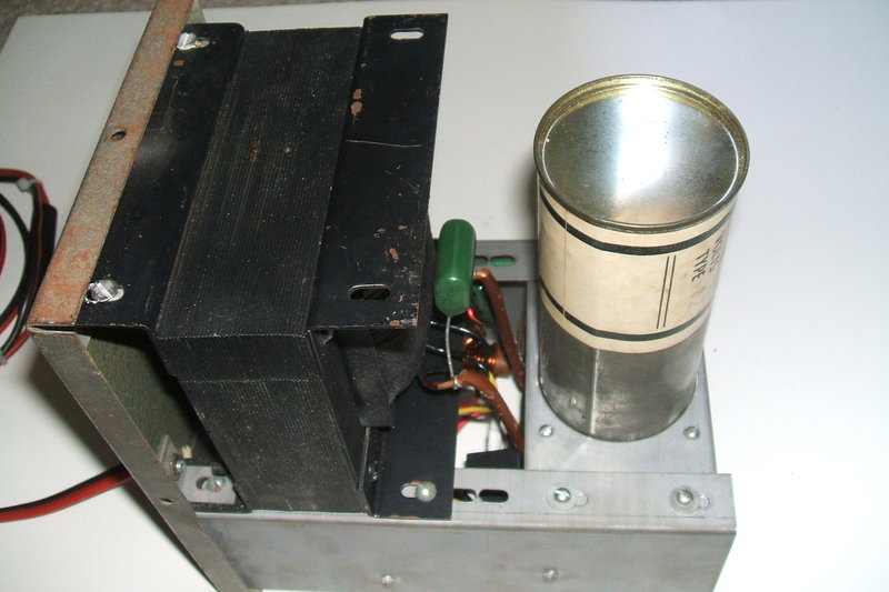
Underneath view with new 3uF timing condenser installed.
How Much did they Cost?
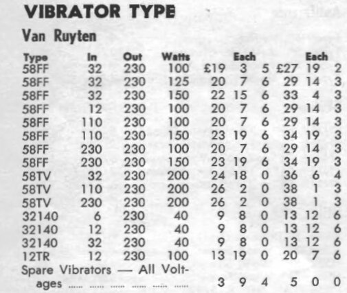
From the 1961 Radio Parts catalog. The 12V model 58FF described
here cost the equivalent of $700 today!
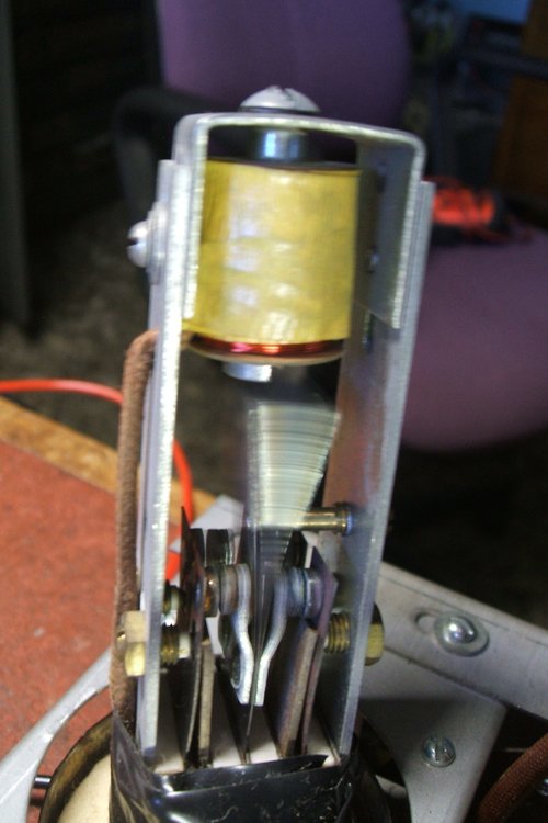
The Vibrator
The vibrator is quite a lot larger than
the typical radio type. It is 120mm tall by 50mm diameter. The origins
are unknown, but as it is 50 cycle and not a modified 60 cycle type, it
could suggest local manufacture. However, it appears to be a copy of an
ATR design.
This vibrator has also been used in Glenradio
inverters. See the Glenradio
100W inverter article for more.
Just because it has a Van Ruyten label,
it does not necessarily mean the company made its own vibrators. There
is also a 32V version of this vibrator.
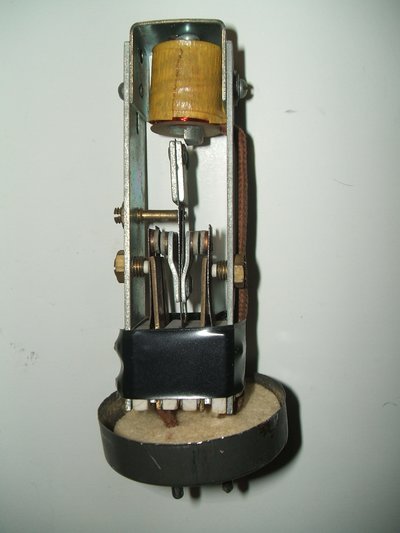
The vibrator is of the dual interrupter
type, but with the connections between contacts on each side made internally.
It is not therefore possible to use it with current sharing circuits, such
as those using two transformer primaries. The contacts are somewhat larger
than those of a typical radio vibrator in view of the much higher current
rating.
While extra paralleled contacts would
appear to double the current rating of the vibrator, this is in actual
fact not so. It is impossible to ensure each set of contacts open and close
at exactly the same time for any length of time. It is at the closing and
opening of the contacts when they are under the most stress, not when they're
actually closed.
This vibrator uses the series drive method for the driving coil. Apart from the extremely long life provided by doing so, there are two reasons why series drive is preferable for an inverter like this. Firstly, because of the more powerful driving coil, the driving current is higher than a radio vibrator. This means coil resistance is also lower. The effect of this is the unbalance in the transformer primary circuit becomes noticeable. Secondly, shunt drive vibrators can be problematic in starting, depending on loading - which can be quite variable for a general purpose AC inverter.
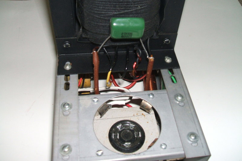
Vibrator fits a UY-5 socket. The 2uF primary buffer is visible connected
across the primary winding.
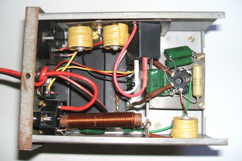
The Circuit
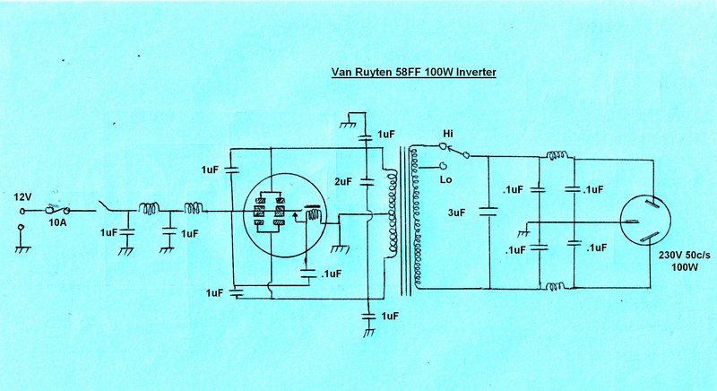
The design is conventional, although with
a slight departure from the usual practice of having the vibrator reed
earthed, and the supply fed to the transformer centre tap. Here, the centre
tap is earthed, and the reed switches the 12V to either side of the primary.
This is the second inverter I have seen that takes this approach, the other
being the Cornell
Dubilier 12A4.
The 12V DC input is filtered for RF by
the usual chokes and condensers. As the condensers are non polarised, input
polarity is not important, except where the inverter is used with an earthed
supply. The inverter case should obviously be connected to the earthed
side of the supply to prevent possible short circuits.
Four 1uF condensers, two from each contact
set to earth, and another two from each contact set to the 12V supply provide
interference suppression. The 2uF across the primary is insufficient to
function completely as a timing condenser, although it would make some
contribution to the overall capacitance required. It would appear to be
more for RF suppression.
The vibrator driving coil has a .1uF across
its contacts, which is essential for spark suppression. A resistor in series
with this condenser would seem to be desirable to limit the capacitor discharge
current when the contacts close. Out of curiosity, I tried running the
vibrator without the condenser and there was a continuous arc across the
contacts. With the .1uF connected, this disappeared completely.
Oak vibrators, although series drive,
do not require an external arc suppression circuit for their driving coils.
This is because of their patented design using an additional short circuited
winding wound with resistance wire, which slows down the rate of magnetic
flux collapse when the contacts open.
Turning now to the secondary circuit, this
is completely conventional, with a high/low switch selecting one of two
tappings on the transformer. Following this is the timing condenser and
a balanced pi filter to reducing RF radiated from the output.
Interestingly, the timing condenser is
connected after the switch, which means the reflected value of buffer capacitance
varies depending on the switch setting. In the "Hi" position there will
be more capacitance than when set to "Lo". However, in practice the value
of buffer capacitance is not as critical as some texts make out - the important
point being that it is never insufficient.
As original to the inverter, the timing capacitance was .56uF. This was found to be completely inadequate as will be described shortly.
Getting it working.
The previous owner had replaced the 12V
supply cable with a length of modern orange four core flex with pairs of
conductors paralleled. The wire gauge looked a bit inadequate for minimal
voltage drop with 10A flowing. Additionally, the original in line fuse
holder had not been retained, thus removing any overload protection.
I used suitable heavy duty figure eight
cable, with a good quality bakelite in line fuse holder with a 10A fuse,
and terminated it with a two pin polarised plug
The next point of call was the timing condenser. This was a paper .56uF type, which for an inverter like this, seemed to be a value lower than one would normally use. To cut a long story short, I found that it indeed it was. Not surprisingly, during testing this condenser failed with excessive leakage.
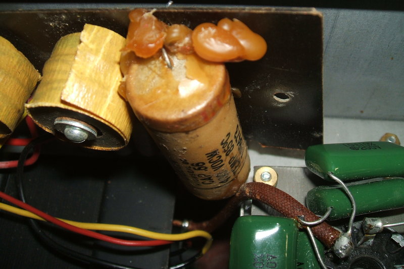
An example of why paper timing condensers need to be replaced.
New Timing Condenser.
Time to have a look at the waveforms and
see what was going on. The standard procedure is to connect a CRO across
the transformer primary, for this is the waveform the vibrator contacts
see. Because one side of the CRO input is earthed, it means the DC supply
must be floating. (The differential inputs of a dual trace CRO can be used
instead).
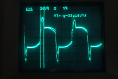
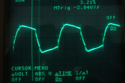
Waveforms with 0.56uF timing capacitor. Left is unloaded; right
is with a 100W incandescent bulb.
As can be seen in the above waveform, there is excessive overshoot. Indeed, there was some arcing at the vibrator contacts. When the inverter was loaded with an incandescent 100W light bulb, the overshoot was eliminated and the arcing stopped, as expected. Clearly, the timing capacitance is inadequate. I can only assume the inverter was mostly run with sufficient load, for the vibrator to have survived this long. Now, to find out what value of timing capacitance would be suitable.
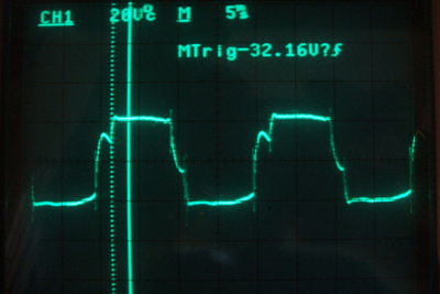
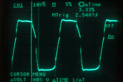
2uF timing condenser, no load.
It didn't take long with a selection of high voltage capacitors to determine that 2uF was the ideal value. No load current consumption on the 12V supply dropped from 4A with the .56uF, to 1.6A with 2uF. As can be seen above, the waveform is much more like it should be. If the inverter was only ever to be used with completely resistive loads, the buffer capacitance could be left at 2uF, but in real world practice it needs to be higher to cater for inductive loads.
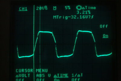
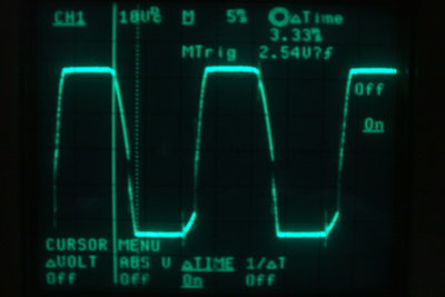
3uF timing condenser, no load at left; with 60W incandescent bulb
load at right.
I used a selection of fluorescent lamps
(20W rapid start [high power factor], double 20W switch start [low power
factor], 15W switch start [low power factor]), and a fan with induction
motor for the tests.
2uF was barely adequate with the L.P.F
loads. In fact, with the 15W lamp, the AC voltage was excessive; around
290V. The optimum capacitance with the 15W lamp was 4uF.
However, the fan and double 20W lamp allowed
a 3uF capacitance with no arcing.
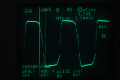
3uF timing with double 20W fluorescent lamp (LPF) at left, and laptop
computer power supply at right.
Grossly excessive timing capacitance is
not desirable, which is why we don't simply install ,say, a 10uF capacitor.
When taken to excess, the current consumption becomes excessive, and the
contacts are liable to arc. Additionally, the capacitor is not correctly
doing its job of reversing the primary voltage at the time when the current
is at a minimum; i.e., when the contacts close and open.
Vibrators used in AC inverters may therefore
be operating under less desirable conditions than those in a DC-DC converter.
Finally, I tested the inverter feeding
a switch mode power supply for a computer. This gave the expected result
of more than optimum timing capacitance being present. Note the steep tilt
as the rising edge commences. The difference with a switchmode power supply
of course is that it draws power only at the voltage peaks of the supply
waveform. The buffer capacitance is not discharged between voltage peaks
as it is when a resistive load is connected.
In summary, for a simple AC inverter like
this, the capacitance must never be below that which is the correct value
for no load. Yet, this value will be found to be insufficient for inductive
loads, such as fluorescent lamps and induction motors. Therefore capacitance
must be added. However, this will then be excess with no load and resistive
loads.
So, a compromise has to be made to increase
the capacitance only by the amount necessary for correct operation with
the inductive loads likely to be used.
In the end, I selected 3uF over 4uF. No
load current consumption is about 2.2A. This is largely swamped out when
the inverter is under load.
Vibrator in action. No arcing visible.
Performance results are as follows. The
12.6V supply was maintained at the plug pins of the supply cable. Of course,
with supply cable resistance, the actual voltage at the transformer primary
will drop under load, and this is reflected in the results.
| Load | Input Current (A)@12.6V | Switch | Output Voltage (Vrms) |
| No load | 2.25 | Low | 270 |
| 2.85 | High | 290 | |
| 60W incandescent | 6.7 | Low | 227 |
| 7.5 | High | 242 | |
| 100W incandescent | 9.3 | Low | 199 |
| >10A | High | 210 | |
| 2x20W fluoro (LPF) | 5.1 | Low | 232 |
| 5.8 | High | 248 | |
| 20W fluoro (HPF) | 4.5 | Low | 232 |
| 4.9 | High | 250 |
The efficiency isn't startling, with 63%
when running the 60W bulb, which is entirely resistive.
The double 20W fluorescent lamp actually
consumes 46W because of ballast losses, and has a power factor of .52.
When powered from this inverter, at 232V, input power at 12.6V is 64W,
meaning an efficiency of 72%.
With the single 20W fluorescent lamp,
this already contains a phase correction capacitor, so has high power factor,
and thus appears largely resistive as a load. It draws 32W with a PF of
.8 at 235V. Input power with the inverter at 12.6V is 57W. Efficiency is
then 56%. Despite this, it would be much better to run this lamp than the
60W bulb because of the fluorescent tube being a more efficient light source.
We can see the effect of the value of
the timing condenser favouring the low power factor inductive load.