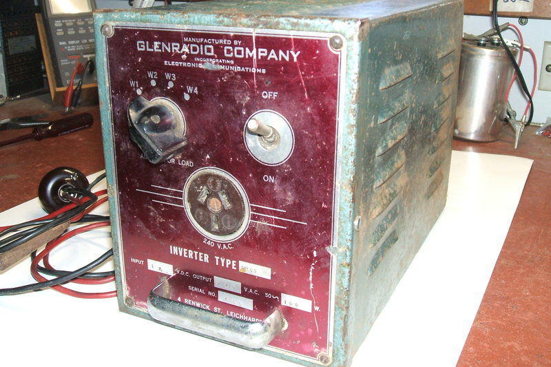
This inverter was bought at a swap meet
in the early 2000's. Of 1950's manufacture, it in some ways resembles the
Van
Ruyten inverter described here, and uses the same Van Ruyten
dual interrupter 50 cycle vibrator.
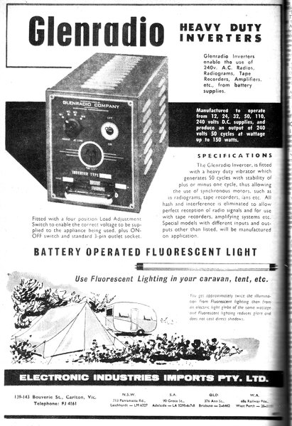
Glenradio appears to be a Melbourne based
company, with branches interstate. This particular inverter was made at
their Sydney branch, at 4 Renwick St, Leichhardt. One of their small shaver
inverters is described here.
As can be seen above, it has had a reasonable
amount of use, but despite that, it was in good electrical condition. It
was actually not necessary to replace any parts! Nevertheless, a few things
did need attention.
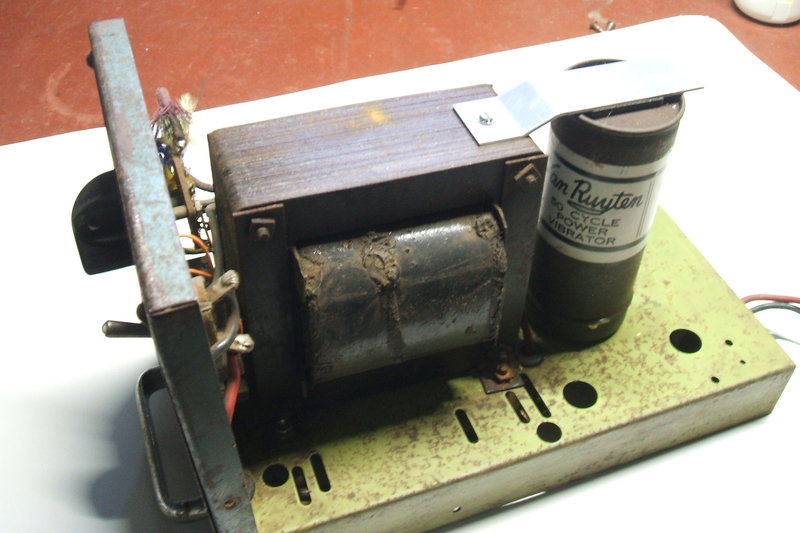
Above chassis view. The vibrator hold down clamp was missing and
had to be fabricated.
The acoustic insulation in the vibrator can had disintegrated and needed replacement. I used thin sponge rubber sheet cut from a camping ground mat. It was then discovered that the vibrator was intermittent, in that tilting the inverter to one side would stop it. This turned out to be the driving coil wire having fractured, and was easily repaired.
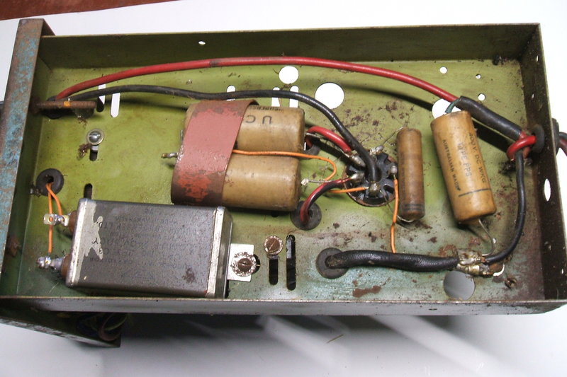
Under chassis view shows utmost simplicty. There is a backyard manufacture
appearance about the construction, yet Glenradio was a well known company.
While the inverter looks nice from the outside, internally it shows cost cutting and an almost slap-dash quality of construction. There is nothing to support the chassis inside the case, except for the front panel. With the heavy power transformer, this means all the weight is concentrated on where the front panel attaches to the chassis. At some time, one of the power transformer mounting screws had come undone and was lost. This only made the whole thing even more flimsy. When I replaced it, I noticed the chassis was now warped. It turned out the mounting feet of the transformer were not all even. Washers had to be packed under the highest foot to fix this. Once done, the chassis was sufficiently rigid.
One noteable aspect of cost cutting is
the .5uF condenser connected to the 12V input. As can be seen from the
above photo, it is merely spliced into the supply lead with no tagstrip
or other chassis mounted terminal. The consequence of this is that as the
supply cable is moved, so does the capacitor. Eventually, one of the capacitor
leads could fail from the constant mechanical movement.
What looks like a random piece of scrap
metal picked off the floor has been used to secure the pair of 2uF condensers
connected to the vibrator socket. At least they have been secured!
It was obvious that there had once been a strap to secure the vibrator in its socket. This was absent when I got the inverter, and it turned out to be very necessary. Without it, the vibrator could fall out of the socket, and the can of the vibrator being able to freely vibrate also caused excessive noise. Rather crudely, a hole had been drilled into the top of the transformer laminations to secure the strap. I constructed another strap out of aluminium with a piece of foam rubber between it and the top of the vibrator, and found a suitable self tapping screw that fitted the hole.
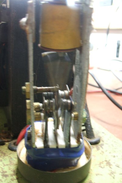
The Vibrator.
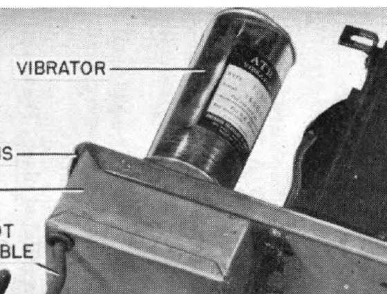
Vibrator as used by ATR.
The origin of the Van Ruyten vibrator appears to be from ATR (American Television & Radio). ATR was a prominent inverter manufacturer in the U.S.. Whether or not Van Ruyten simply copied the design for manufacture in Australia, or if they were made by ATR for 50 cycles and imported, is not known.
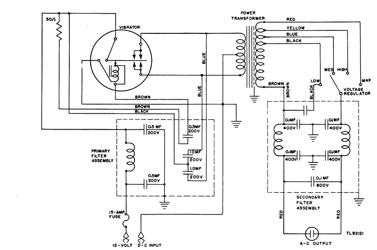
Circuit of the ATR TM11-2519 inverter.
The ATR TM11-2519 is a WW2 military inverter,
providing 100W output. It is clear that the vibrator is the same type,
and operates with the transformer centre tap earthed. Noteable is the proper
RC network across the vibrator drive coil contacts; this being a 50R resistor
in series with a .5uF condenser. With no resistor as in the Van Ruyten
and Glenradio, the drive contacts carry the full discharge current of the
associated capacitor when the contacts close. Also noteable is that most
of the buffer capacitance is permanently connected to one secondary tapping,
and is not switched.
The Circuit.
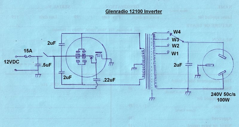
The design of this is certainly minimalist.
It would be harder to imagine a more simple but practical 100W inverter.
Unlike the Van Ruyten, there is not one RF choke to be seen. There is no
output filtering except for that provided by the buffer condenser.
As with the Van Ruyten, the vibrator switches
the 12V supply to either side of the primary winding and the centre tap
is earthed. The driving coil contact has a .22uF spark supression condenser,
whereas the Van Ruyten uses .1uF.
2uF condensers are connected across the
vibrator power contacts for spark suppression. While there is a small amount
of buffer capacitance also provided by these condensers, most of the buffer
capacitance is provided by another 2uF, this time across the transformer
secondary.
Like the Van Ruyten, there is an output
load switch selecting the appropriate secondary tapping. Here, there are
four positions instead of the VR's two. The buffer condenser is connected
after the switch, and as expected, the reflected buffer capacitance as
seen at the transformer primary varies depending on the switch setting.
The Glenradio has an unbalanced output
with one side of the socket earthed.
An inline 15A fuse protects the wiring
in case of an excessive overload or shorted vibrator contacts. Surprisingly,
it was still present when I got the inverter. I terminated the supply cable
with a two pin polarised plug to make easy connection to my car or house
12V electrical systems.
From Radio, Television & Hobbies, March 1959.
Testing the Glenradio.
Despite the cost cutting construction,
the performance was good. The usual selection of incandescent and fluorescent
lamp loads were tested.
As seems to be usual for this type of
inverter, the buffer condenser value is higher than the ideal, in order
to cope with inductive loads.
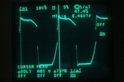
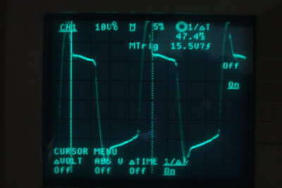
No load vibrator waveform.
It was noted that the vibrator frequency is slightly low, at just over 47c/s. The waveform also shows a degree of non symmetry, most likely caused by one set of contacts being further away from the reed than the other. The vibrator design allows for easy adjustment, but it was not felt necessary for now.
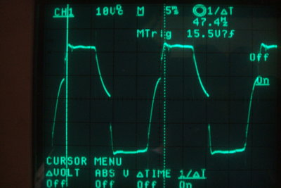
60W incandescent lamp load at left. 40W low power factor fluorescent
lamp load, at right.
With a purely resistive load, as in the
form of a 60W incandescent light bulb, the waveform is as expected. The
effect of the lamp discharging the buffer capacitance in between contact
closures can be seen.
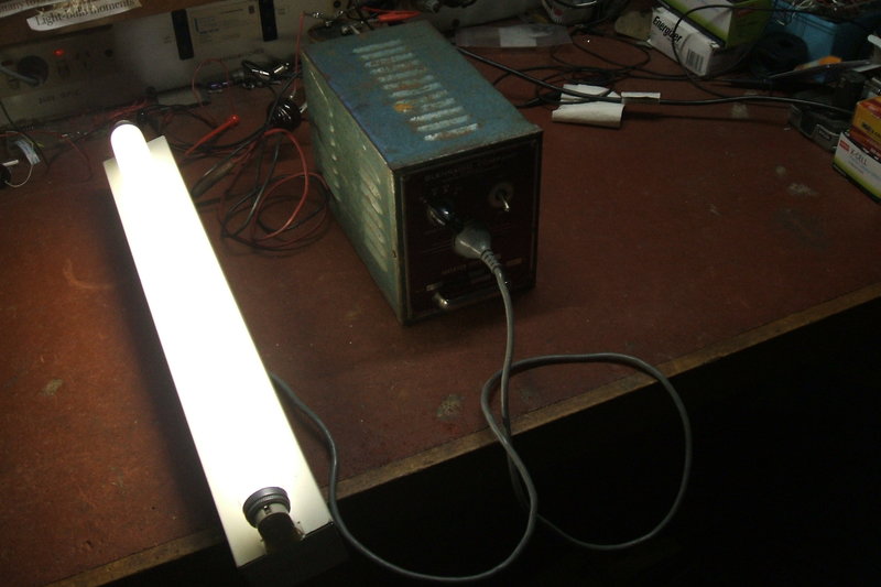
When a 40W low power factor fluorescent
lamp was connected, some overshoot was visible. This indicates insufficient
buffer capacitance. Despite this, sparking at the vibrator contacts was
virtually non existant. This would be the limit of low power factor loads
I'd be happy running off this inverter.
No sparking when running a low power factor fluorescent lamp.
Performance
With the various loads connected, and
12.6V at the two pin plug, the following resuslts were obtained at each
of the output settings, W1 to W4.
Current values in brackets are for the
12.6V supply.
| Load | W1 | W2 | W3 | W4 |
| 40W incandescent | 219V (4.3A) | 236V (4.7A) | 251V (5.2A) | 265V (5.8A) |
| 60W incandescent | 207V (5.3A) | 221V (5.9A) | 236V (6.5A) | 247V (7.1A) |
| 100W incandescent | 191V (8A) | 202V (8.7A) | 213V (9.7A) | 226 (>10A) |
| 20W fluorescent HPF | 219V (3.8A) | 233V (4.1A) | 248V (4.6A) | 265V (5A) |
| 40W fluorescent LPF | 225V (4.2A) | 244V (4.9A) | 265V (5.9A) | 283V (6.9A) |
| No load current 12.6V | 2.15A | 2.4A | 2.8A | 3.15A |
The effect of excessive buffer capacitance
can clearly be seen, with minimum current at the W1 setting. As mentioned
elsewhere, it would be possible to reduce the no load current further,
but the inverter would be restricted to powering purely resistive loads
only.
Using the 60W load as a guide to efficiency,
we can see that current draw at 12.6V is 6.5A for the optimum output setting
(W3). This equates to 82W input power, and thus an efficiency of 73%. This
is somewhat better than the Van Ruyten inverter, but note that the VR has
a higher value of buffer capacitance, compared to the ideal, than the Glenradio.
Not surprisingly, the 20W HPF fluorescent
lamp is a poor choice of load with regards to efficiency. As it already
contains a phase correction condenser, the over all buffer capacitance
is much higher than optimum. At the W2 setting, input power is 52W, which
is an efficiency of 62%, given that the lamp including ballast losses draws
32W with a PF of .8.
The 40W LPF fluorescent lamp is more efficient
as a load. With ballast losses it draws 46W at 235V. When powered from
the Glenradio on the W2 setting, input current at 12.6V is 62W. Efficiency
is 74%.
Glenradio inverter powering a high power factor 20W fluorescent
lamp.
A 15W low power factor fluorescent lamp
was also tested. However, the voltage was grossly excessive, proably due
to a resonance effect with the ballast and the buffer condenser. The ballast
would have somewhat more inductance than that of the 20W or 40W lamps tested.
In any case, such a low power lamp is
not recommended from an efficiency point of view.
The important thing to realise is that
inverters do not provide the same type of output as the reticulated supply
mains, and some thought needs to be given when deciding to power an appliance
from an inverter.

Note that Electronic Industries Imports was also the origin of Ferrocart
vibrators. This suggests some kind of connection between Glenradio and
Astor.