This inverter is not part of my collection but belongs to a fellow HRSA member who asked if I could repair it. As vintage inverters are one of my specialties, I thought it would be an interesting exercise to get it going. I had seen this model before, so gathered it was popular at the time, but now I had the chance to see what was inside.
AWA created two inverter models for running
TV sets from 32V DC supplies. Until the end of the 1960's, perhaps even
into the 1970's, 32V DC supplies were common in rural areas of Australia
with no reticulated mains supply. In their basic form, a single cylinder
engine drove a generator which charged a bank of 16 two volt cells. A wind
generator was sometimes used instead of the engine.
With perhaps the exception of refrigerators,
all the common household appliances were available in 32V. Radios, toasters,
electric drills, fans, vacuum cleaners, etc. could all be bought. 32V light
bulbs with the standard B22 bayonet base were also freely available.
When television came to Australia in 1956,
there were still many localities with no mains power which were within
receiving distance of the capital city TV stations. And, when the rural
TV services started in the early 1960's there were even more potential
viewers with no mains supply.
Obviously, there was a market for 32V
television sets. One manufacturer, Ferris, did make a 32V TV set which
used a vibrator power supply.
It was of course possible to use a sufficiently
heavy duty inverter to run a normal 240V television set from the 32V supply.
At the time this was either a vibrator inverter or a rotary inverter.
By the early 1960's, transistor technology was such that high power solid state inverters were now becoming practical. AWA did not make 32V televisions, but instead provided an inverter which allowed a conventional 240V set to be used on a 32V supply.
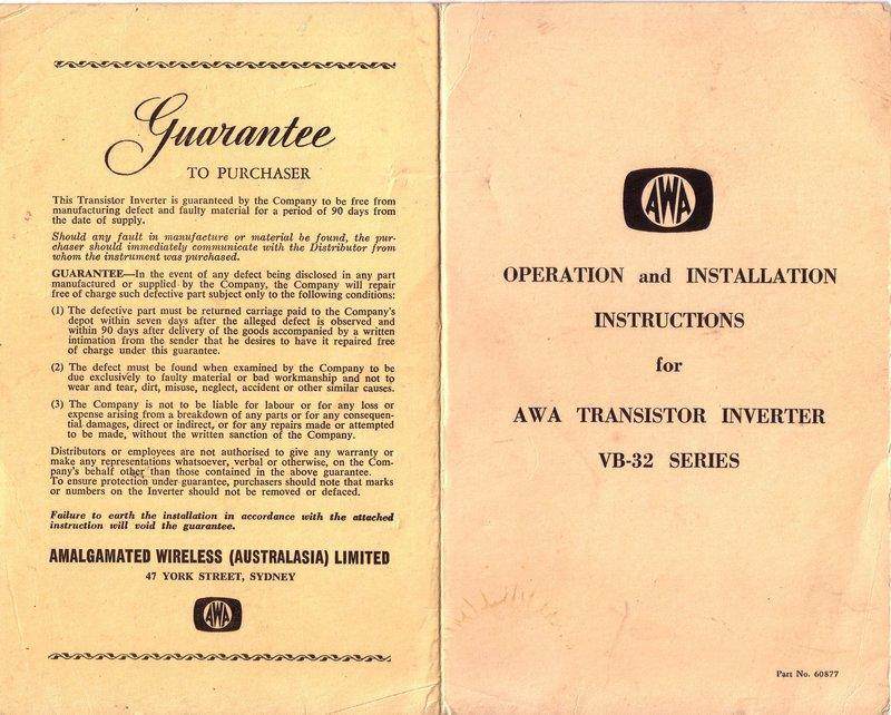
Instructions for the VB-32A.
AWA made two such inverters, the VC-32
and VB-32QA. Both these models are very similar, with the exception of
the output transformer and associated circuitry.
The VC-32 requires some modification to
the TV set, in that it provides separate heater and B+ supplies which are
fed to the set via a multiway cable. The existing power transformer inside
the set is disconnected, and the wires from the inverter fed to the relevant
supply points. The VC-32 is designed for sets that use a voltage doubling
power supply. That is, those sets with a transformer secondary of around
115V, as well as the usual 6.3V heater winding. The 115V is fed into a
full wave voltage doubling circuit to provide the 250V B+. This design
became standard in Australia from around 1959, when silicon rectifier diodes
started to appear. It made for a smaller (cheaper) power transformer because
the secondary only required a quarter of the number of turns, compared
to a full wave valve power supply.
Not all sets however, use a voltage doubling rectifier, and for these, the VB-32QA was available. It provides 240V AC output which drives the TV set in the normal way with no modifications.
Given the VC-32 manual is dated November 1963, and the VB-32QA is dated July 1963, it would appear that the VB-32QA was the earlier of the two models. This seems odd at first, because surely just plugging in an unmodified TV to the inverter is more desirable than having to modify a set by disconnecting numerous transformer leads, and then connecting multiple wires to different points in the set.
However, on closer inspection, the VC-32 method is actually more efficient because one power transformer (the one in the set) is eliminated along with all its losses. In the case of sets using valve rectifiers, it was essential to use the VB-32QA. Indeed, the nominal input current for the VC-32 is 6A, compared to 8.5A for the VB-32QA.
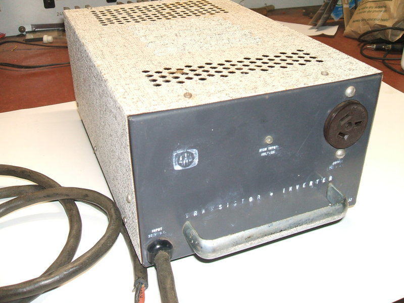
The VB-32QA Inverter.
The inverter is constructed on a steel
chassis with a Marvi-Plate lid with a typical 1960's pattern printed on
it. The rear of the cabinet actually consists of the output transistor
heatsinks. On the front is the 240V output socket, over voltage and reverse
polarity warning light, and a chrome plated handle. A short length of two
core rubber flex emerges from the front panel via a cord grip grommet for
the 32V supply. Four rubber feet are provided beneath the cabinet.
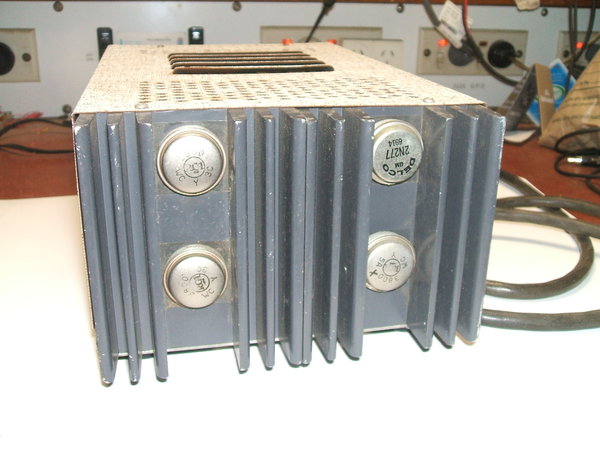
Rear panel shows heatsinks and the four 2N277 / 3800 power transistors.
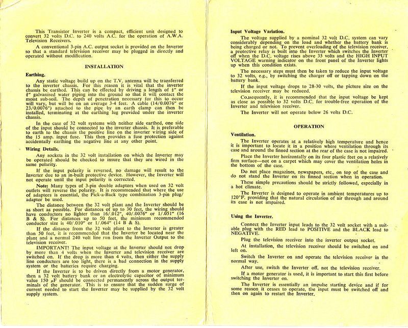
Specifications are for an output power
of 180W at 240V AC with an input current of 8.5A at 32V DC. Output frequency
is 60-65c/s and depends on loading and supply voltage. The choice of output
frequency is interesting, and was perhaps chosen for more efficient transformer
operation. A potential problem is that unless the B+ filtering in the TV
is particularly good, a 10c/s weave will be observed in the picture which
is scanning at 50 fields per second.
An over-voltage and reverse polarity protection
circuit disable the inverter, should the supply connection polarity or
voltage input be likely to damage the inverter or television set.
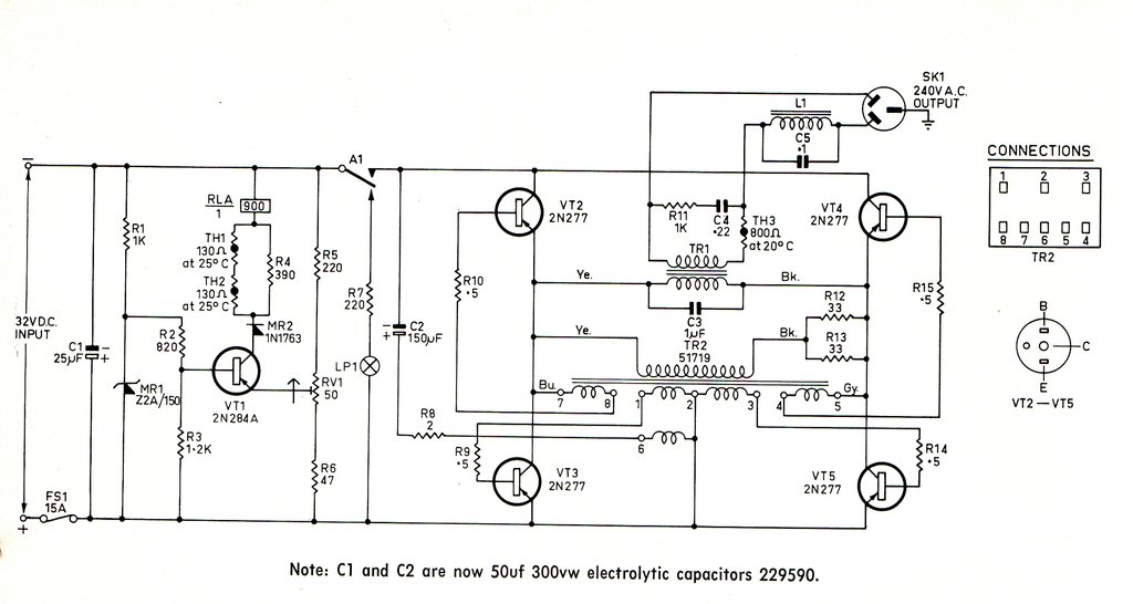
Self Oscillating Design.
The inverter is of the self oscillating
type whereby feedback to cause oscillation is provided by the oscillator
transformer. Another AWA self oscillating inverter has been described here.
Unlike most inverters, the VB-32QA (and VC32) use an H-bridge to drive
the step-up transformer.
This simplifies the transformer in that
only a single primary winding is required. The trade-off is that four transistors
are required instead of two, as is the case with a centre-tapped primary
winding.
TR1 is the step-up transformer. It can
be seen that when VT2 and VT5 conduct, the primary winding will be supplied
with 32V, with negative on the yellow wire, and positive on the blue wire.
Now, when VT2 and VT5 switch off, and then VT3 and VT4 switch on, the transformer
is again supplied with 32V. However, now the yellow wire is positive, and
the blue wire is negative. Hence, 32V AC (64V peak to peak) is applied
to the primary.
In order to drive the transistor bases,
TR2 provides the low impedance drive required. It also provides the isolation
required for each transistor base. By connecting TR2's primary to the primary
of the output transformer out of phase, it can be seen that positive feedback
exists, and thus the circuit oscillates.
However, like all self oscillating transformer
circuits, some means must be provided to start the oscillation. Up to this
point, when the inverter was first switched on, nothing would happen. One
of the transistors must be given a kick to cause the positive feedback
process to begin.
Here, C2 and R8 provide a starting pulse
which is fed into a winding of TR2. When the inverter is first powered
up, the charging current of C2 flows via R8 into the winding between pin
6 and 2. This causes a pulse to appear at each of the transistor bases.
Because of slight differences in each of the transistors, one of the transistors
will always switch on before the others. And so, with one transistor pulsed
into conduction, the circuit starts oscillating. C2 has no further effect
and merely remains charged at 32V for the remaining time the inverter is
powered up.
Output Circuit.
A square wave output appears at the secondary
of TR1. This is fine for running loads like incandescent lamps or soldering
irons, which care nothing of the waveform. For television use there is
a problem. With a square wave, the rms and peak values are the same. So
in the case of a 240V square wave inverter, the output is 240V rms, and
the peak value is also 240V. With a sinusoidal supply, like that of the
mains supply, the peak is the rms multiplied by the square root of two;
i.e. 340V.
Where a capacitor input rectifier circuit
is used in an appliance, the filter capacitor charges to the peak of the
supply. Assume our TV set has a power transformer with a 250V secondary
winding. In the normal way, fed from the mains supply, the first filter
capacitor would charge to about 350V. Now, when this same TV set is fed
from a square wave supply, the first filter capacitor charges to only 250V.
Thus, we see a considerable loss of B+ voltage, and the TV would not perform
at its best, with one obvious fault being a shrunken picture.
What if we make the inverter produce a
peak voltage of 340V, so the set thought it was running off a 240V sine
wave? Yes, the first filter capacitor would charge to the correct voltage,
and the B+ would be correct. The problem now is that the valve heaters
would be grossly over run as they are heated by the rms value and not the
peak.
The above illustrates a very real limitation
with square wave inverters, and why they are not always an acceptable substitute
for the mains supply.
So, how does the VB-32QA get around this
problem? Effectively, the inverter does actually provide a 340V peak, but
the rms is reduced to 240V by the filter consisting of L1 and C5.
The waveform is converted into what AWA
call a "modified square wave". That is, the square wave does indeed have
the correct peak voltage, but the duty cycle is reduced so the rms is also
correct. In the modern day, inexpensive solid state inverters do exactly
the same thing, so that electronic loads work correctly, but the means
of obtaining this waveform is quite different.
A thermistor, TH3, is in series with the output to provide a soft start. Heavily loaded, as with a TV set full of cold valve heaters, a self oscillating inverter may sometimes have difficulty starting. This is because excess loading deprives the transistors of sufficient base current to start switching.
C3, C4, and R11 also provide waveshaping, but mainly for the switching transistors so they are not exposed to excessive voltage spikes. R9, R10, R14, and R15 limit the base current and accommodate slightly different base characteristics for individual transistors. The transistors themselves are an early germanium power type, 2N277, or 3800.
Over-Voltage and Reverse Polarity
Protection.
At this point, the circuitry just described
could be connected to 32V DC and would work as intended. In the real world,
there is a good chance that the "32V" might not be exactly that. Being
solid state, the inverter is polarity conscious. Should the inverter be
connected with incorrect polarity, it will certainly not work, and the
transistors may be destroyed.
It is easy to imagine that with a typical
32V installation not much regard might be given to polarity. Lights, motor
driven and heating appliances do not care about polarity. Only when we
get to the radio does it begin to matter. A temporary application of reverse
polarity here is unlikely to do any damage, as the valves simply do not
conduct at all. The only at risk components are the filter electrolytic
capacitors.
It is an unfortunate situation that standard 240V plugs of the three flat pin type were used in many 32V installations. Even today, working displays of vintage 32V equipment often use 240V connectors. This is especially undesirable considering a proper plug for 32V was (and still is) widely available (Clipsal 482/32). The VB-32QA manual acknowledges the use of 240V plugs used on 32V, and also the use of the type of three pin double adaptor which reverses polarity. Hence, there's a very likely risk the inverter will be fed with reverse polarity.
The next risk to the inverter (and TV set)
is excess input voltage. If the batteries are being charged, the voltage
is likely to be well in excess of 32V. As it is, the charge voltage of
a 32V bank of batteries is at least 37V. This will be even higher if the
batteries are in poor condition or the charge current is higher than it
should be. Keep in mind that many such installations were used and maintained
by those with a poor understanding of things electrical. With excess input
voltage to the inverter, there is a real risk that transistor voltages
will be exceeded causing breakdown. Assuming the transistors stand up to
this, the TV set will have its valve heaters over-run and the B+ will be
excessive.
To prevent this, the VB-32QA also has
an over-voltage circuit which prevents the inverter operating above 36V.
The manual recommends tapping the inverter supply further down the battery
bank if the batteries must be charged while the inverter is in use.
The reverse polarity and over-voltage protection
is performed by RLA/1. The N.O. contacts of this relay switch the 32V supply
to the inverter if polarity is correct and supply is under 36V. If supply
is not correct, the supply is diverted to a warning lamp via the N.C. contacts.
This is a 12V 2.2W MES bulb in series with R7.
The relay will not operate when polarity
is incorrect because of diode MR2 in series with the relay coil. Thus,
the warning lamp also indicates incorrect polarity, although the front
panel label only mentions "High Input Voltage".
The over-voltage sensing circuit is based
around zener diode MR1 which provides a reference voltage, immune to supply
voltage variations.
Transistor VT1 conducts when the base
voltage is less than the emitter voltage. This is the same as saying the
transistor conducts when the emitter voltage is greater than the base voltage
(note the transistor is PNP). Emitter voltage is taken from an adjustable
voltage divider (set by RV1) which is fed from the 32V supply. When the
voltage exceeds 36V, the voltage at the wiper of RV1 is greater than the
base of VT1. The transistor conducts, and the relay coil pulls in, shutting
off the inverter and activating the warning light.
Surprisingly, there is no power switch on the inverter. Non technical users are likely to switch off the television with its own power switch, leaving the inverter running. This draws about 2A from the 32V supply with no load and will needlessly drain the batteries. While it does make a slight buzzing sound when running, this might not always be noticed, especially if the inverter is located away from the television.
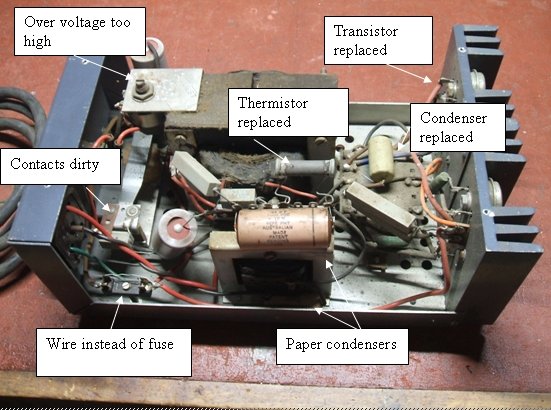
Things noticed when the inverter was examined and tested.
It was noted there was some variation with the service manual. The temperature compensation components for the over voltage protection circuit were not present. These are R4, TH1 and TH2. The service manual mentions these not being present in early versions. However, C1 and C2 were 50uF 300V types which are apparently fitted to later versions. The unusually high voltage rating is interesting. For C1, it could be that a 300V rated electrolytic will withstand reverse polarity better than the original 65V type. For C2, this would not be an issue, so the reason for the voltage increase is not clear. It could simply be that the higher voltage type was chosen because it is physically much larger, and copes better with the ripple current. This too would apply to C1.
Transistors OK.
With a 30V bench supply connected, the
inverter burst into oscillation. This was fortunate, because I was concerned
about faulty output transistors. There are undoubtedly stocks of 2N277's
around, but they will only get harder to get as time goes on. While there
are many modern silicon power transistors that could be used, the heatsink
would have to be re-drilled to fit their newer packages. Also is the concern
that the base drive might not be sufficient for silicon types.
First thing to do was to replace both C3 and C4 with polypropylene 250VAC types. Leaving paper types here is a recipe for future problems. If the leakage of C4 became excessive, then R11 would burn out. If C3 broke down, the inverter would produce excessive rms output voltage.
Next, the piece of "fuse" wire was removed and a 15A fuse inserted. The inverter was connected to a couple of paralleled 30V 3A bench supplies and was able to run a 100W light bulb without any problem. It was noted that under low load the output voltage was excessive. 300V was recorded with a 60W bulb, with 32V input. It was necessary to drop the supply to around 25V to get the bulb voltage down to 240V. No doubt, with the higher loading of a TV set, which is what the inverter is designed to run, the voltage would be closer to 240V, especially allowing for voltage drop in the supply. This kind of poor regulation is quite normal with inverters of this type. To compensate for this, it is usual to provide a selection of tappings on the output transformer (see the other high powered inverters described elsewhere on this site). As the VB-32QA is designed for one specific load only, it was not necessary to provide this feature.
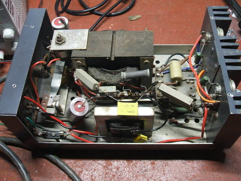
Inverter with parts replaced. Note the two yellow capacitors.
Over-Voltage Circuit
The over-voltage protection circuit was
then tested. No doubt due to component drift (the resistors here are carbon
IRC types), it was found that about 41V was required to trip it. Adjustment
of RV1 returned this to the specified 36V. When the circuit was activated
it was noted that the warning light was intermittent. This simply required
a clean of the relay contacts. Even so, there is little spring tension
on the relay contacts, so the long term reliability is questionable. Furthermore,
as the warning light would be (should be) seldom activated, there will
be no "electrical cleaning" of the N.C. contacts.
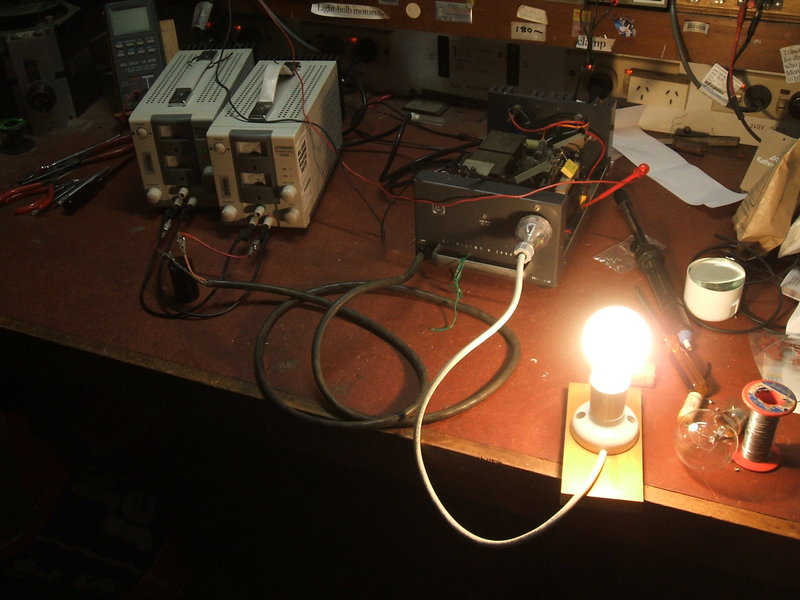
Inverter operating a 100W incandescent lamp.
| Input Current at 32V | Output Voltage | Input for 240V output | |
| No Load | 2.1A | 365V | 20V |
| 15W | 3A | 332V | 23V |
| 60W | 4.9A | 295V | 25V |
| 100W | 6.5A | 270V | 27V |
| 175W | 9.3A | 253V | 30V |
| AWA TV | 8A | 253V | not measured |
| Healing TV | 8.8A | 243V | 30V |
It can be seen from this table that the
inverter produces excess output voltage at anything less than full load.
The reason for the "television only" specification should now be clear.
Having said that, the inverter can be
used to power other resistive loads of less than 180W, provided the input
voltage is adjusted as necessary.
For instance, a valve mantel radio, drawing
about 40W, would be suitable, provided the inverter was fed with 24V. It
would be wise to actually measure the AC output under load when setting
the input voltage - this table is only a guide.
Any loads which are frequency critical
could be problematic due to the 60c/s output. For example, gramophone motors
will run fast.
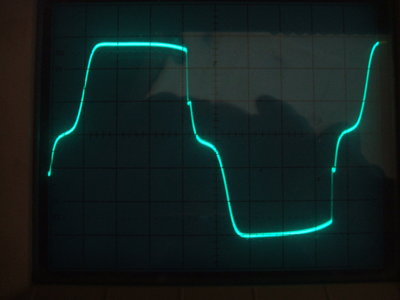
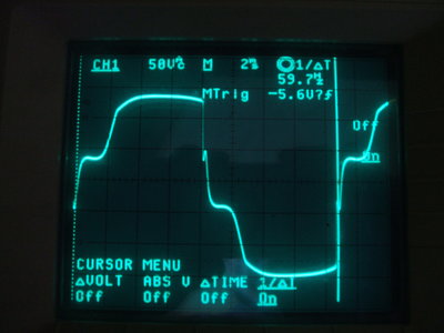
Output waveforms; left for incandescent lamps and right for the
Healing TV set.
Results with the television loads were
interesting. The AWA set is a 23" 110 degree D65 model, with a 34 series
chassis. It dates from around 1964 and uses a voltage doubling rectifier.
It is in fact just the kind of set that the VC-32 was intended for. The
Healing is a 17" 70 degree set from 1956 and uses a conventional valve
rectifier.
Output frequency of the inverter was 60c/s.
A 10c/s modulation of the picture brightness was quite noticeable on the
AWA set and detracts from the entertainment quality. This was much less
evident with the Healing.
The output frequency of the inverter was
noticeably high when the sets were first switched on. Input current was
over 10A with cold valve heaters. This is typical of self oscillating inverters
where an increase in load increases the output frequency.
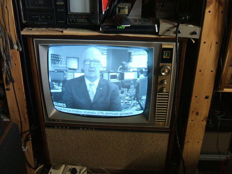
The VB-32QA operating an AWA 34 series TV set. The beat between
the field frequency and inverter frequency was evident but is not visible
in this photo.
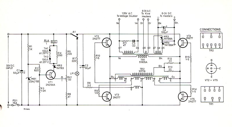
For the sake of completeness, the circuit
of the VC-32 is shown above. As can be seen, it is the same as the VB-32QA
except for TR1 and associated secondary circuitry. The transistor base
resistors have been increased to 1.5 ohms. The 1uF across the output transformer
primary is also not present.
It is a curious thing as to why the valve
heaters are fed from DC. If anything, the voltage drop across the rectifier
diodes would detract from efficiency. Given the valve heaters are all indirectly
heated, there is no need for the DC supply. With about 8A of heater current,
the 150uF filter condenser would have little effect. Interestingly, the
picture tube heater is fed from AC.