AWA 1H60668 12-240V 40W Inverter.
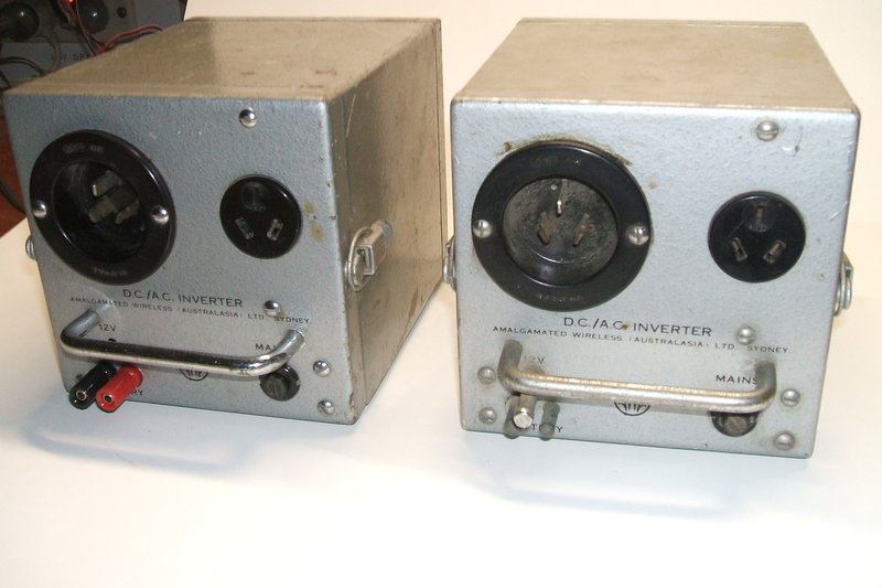
This pair of inverters was purchased off
ebay from a seller in Tasmania. It is not clear what exactly they were
intended to power. The 1H60668 is clearly not something for ordinary domestic
use. The battery connector is a type that was used with AWA Carphone power
supplies. The ebay seller unfortunately did not send the documentation
with the inverters shown in the ad, although he insisted that he had done
so. All I had were the ebay photos of part of the documentation. Sometime
later, I discovered the inverter was shown in AWA's "Mobile Radio-Telephone"
catalog from the mid 1960's. Alas, it is still not clear what it is meant
to be used for, and is merely listed amongst other two way radio equipment.
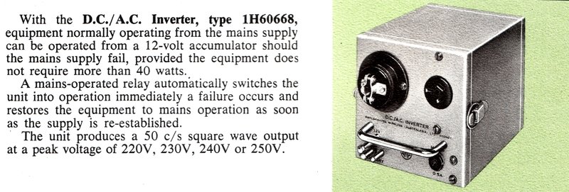
From the AWA Mobile Radio-Telephone catalog.
It was known that output was 40W at 250V
50c/s, from this and the ebay documentation, and that the input is 12V.
Perhaps the most unusual aspect is the
inclusion of a mains input socket. Normally the mains input feeds the output
socket, but when the mains power is not present, the inverter switches
on, and the output socket is switched over to the inverter's output transformer.
In this regard, it actually functions as an uninterruptable power supply.
No on/off power switching is provided which supports the UPS intention.
However, there is no facility for battery charging when mains power
is present.
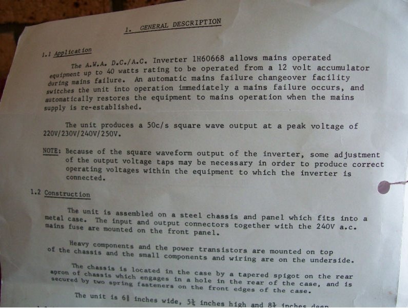
All I have of the instructions.
The inverter is built on a steel chassis
which clips into the enclosure, in the same way as the AWA Carphone power
supplies. It was obvious by the presence of more than one transformer,
and only two transistors, that it was a self oscillating design. It appears
to be from the mid 1960's, given the components used.
The Circuit.
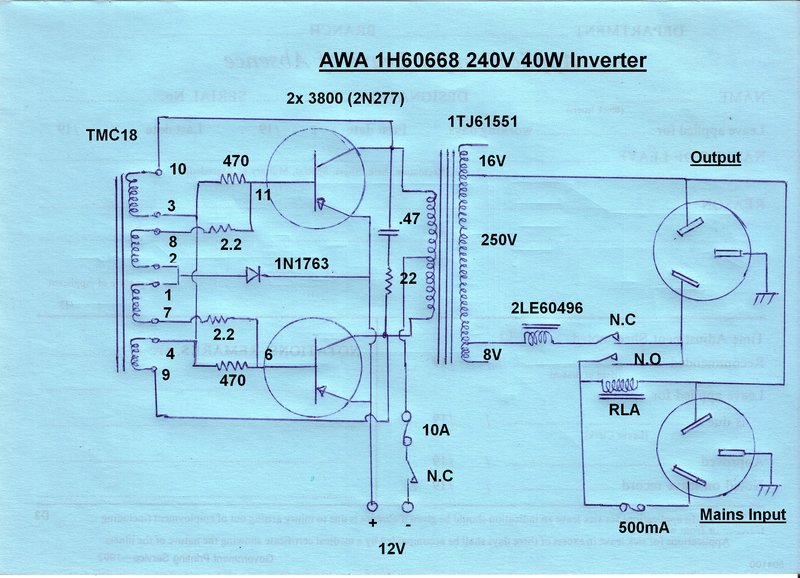
Electrically, there is nothing particularly
unusual about the design. With the exception of the changeover contactor
and mains input socket, it is just like the first generation solid state
inverters that were popular in the U.S. during the 1960's.
Oscillation occurs by virtue of the feedback
from the output transformer to the smaller oscillator transformer which
drives the transistor bases.
The 470 ohm resistors provide a small
amount of forward bias so the transistors conduct enough to get the oscillation
started. Because of slight differences in the transistors, and other component
tolerances, one transistor will always start conducting before the other.
In theory, with perfect components, this kind of inverter would actually
not work!
The 2.2 ohm resistors limit the base current
and allow for slightly different transistor characteristics. The 1N1763
diode prevents the opposite transistor, to that which is conducting, being
fed with reverse base voltage.
The oscillator transformer is unusually
not made by AWA, but rather by TMC, which is the Telephone Manufacturing
Company, an organisation that was involved with Pye at one time. This was
the most difficult part of the circuit to trace out, but it had to be done.
Two of the transformer tags, pins 6 and 11 are merely used as tie points.
The transformer housing is reminiscent of the popular Rola "Isocore" design.
Between the transistor collectors is an
RC network to suppress switching spikes. A limitation of self oscillating
inverters is that output frequency depends on the load and supply voltage.
Indeed, as the tests showed, this inverter showed some variation. It would
be thus unsuitable for frequency critical loads such as timers or clocks.
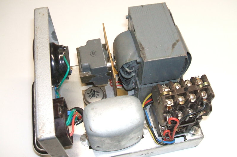
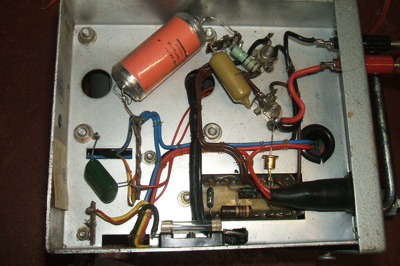
Chassis view. At bottom left is the oscillator transformer. To its
right is the mains contactor.
The transformer primary is driven in the
usual way by alternate switching of the transistors. Protection is via
a 10A fuse but this is too high to protect the transformer from overload.
It would likely only ever blow if a transistor short circuited. No specific
reverse polarity protection is provided. The transistors are a long obsolete
PNP germanium type, RCA type 3800. This is equivalent to 2N277 and
rated at 50V 25A, which is more than enough for this small inverter!
These transistors were also used in AWA's
32V television inverters.
The transformer secondary is tapped, and
according to the literature, provides either 220, 230, 240, or 250V. Why
this selection of voltages needs to be provided is not clear, when any
40W or smaller load is not likely to be particularly voltage sensitive
anyway. The documentation does mention these voltages being peak, which
is correct for a square wave. The rms is the same in this case.
There is a 240V contactor which does the
changeover function. When the mains is applied, the coil pulls in the contacts,
disconnecting the 12V supply and the transformer secondary, but connecting
the input socket to the output. A 500mA fuse protects the mains wiring,
but is not used when the inverter is operating.
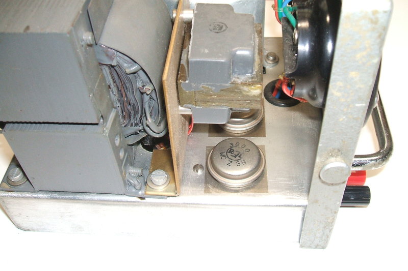
A view of the transistors and output choke.
A small choke is included in the output
from the transformer to smooth the waveform.
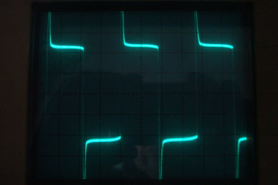
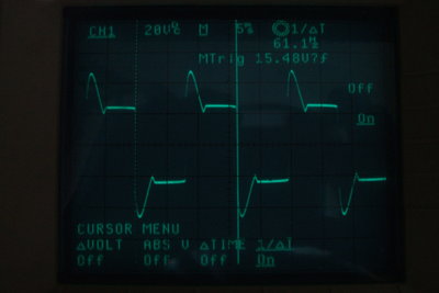
The effectiveness of the choke is clear. These waveforms show the
input and output sides of the choke with a 40W resistive load.
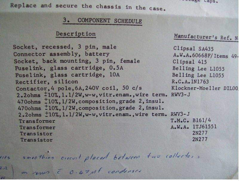
Parts list. Note the had written addition referring to the RC network
between the transistor collectors.
Bodgie Mods.
Present in both inverters were some capacitors
which didn't quite look as they were put there by AWA. Closer investigation
showed quite a dangerous arrangement with them. Inverter s/n 94 had a .47uF
630V Styroseal capacitor connected between the mains neutral and the chassis.
Additionally, there was another .47uF,
this time a greencap, from the live side of the transformer secondary to
the chassis.
When operating off the DC supply, with
no mains connected to the input socket, this simply results in a balanced
output. However, with the mains connected it is a potentially dangerous
situation. Depending on the mains polarity, which incidentally was not
standardised when this inverter was made, what is intended as the neutral
could be the live! The reactance of the .47uF capacitor is low enough to
provide a nasty shock if there is no earth connection to the chassis. Worse
still is if the capacitor should break down. If the contactor had been
wired with double pole switching, then it could have been possible to get
away with the scheme - but it wasn't.
The large red capacitor and the greencap at the bottom left were
added by a previous owner.
Inverter s/n 99 had only one capacitor
added; this time a decrepit wax dipped paper type of .22uF, again between
neutral and chassis. Even more likely is a breakdown with this type of
capacitor.
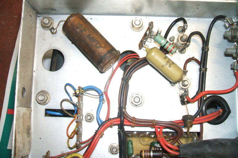
In this inverter, an old wax paper capacitor has been added. The
blue wires are connected to the mains.
Such capacitors would have been added to
round off the waveform to reduce RFI, which suggests the inverters were
used to power radio receivers of some sort. I removed them and tested the
inverter with an HMV mid 1960's valve radio, and found no RFI problems.
It was necessary to earth the 12V supply however, otherwise a buzzing could
be heard through the radio.
What is visible of the parts list does
not show if there were other capacitors on the output side of the transformer,
and by the hand written mention of the "smoothing circuit placed between
two collectors" it seems the 22R and .47uF network was a later modification.
It, however, appears to be a legitimate update to the design by AWA.
In order to use one of the inverters, and
seeing as the two round pin polarised connector would never likely to appear,
I installed binding posts for the 12V input.
Performance.
Testing was done with 12.6V at the input
terminals, and with no load, 15W and 40W incandescent lamp loads.
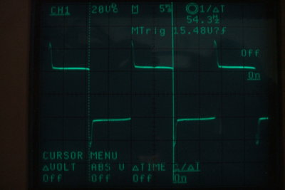
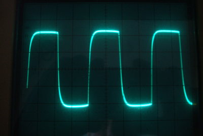
Frequency variation under load. These waveforms were taken between
the transistor collectors.
With the 40W load, frequency was 54.3Hz
and under no load it increased to 61.1Hz.
| Load |
Input Current |
Output Volts |
Efficiency |
| 0 |
530mA |
289V |
0% |
| 15W |
1.75A |
254V |
68% |
| 40W |
3.7A |
216V |
86% |
As can be seen from the above table, efficiency
improves considerably at full load. Regulation is adequate for the loads
likely to be used. Very low power loads (under 15W) are likely to be those
where the supply is rectified to provide DC, and so the apparently excessive
AC output voltage would actually be to their advantage.
Home