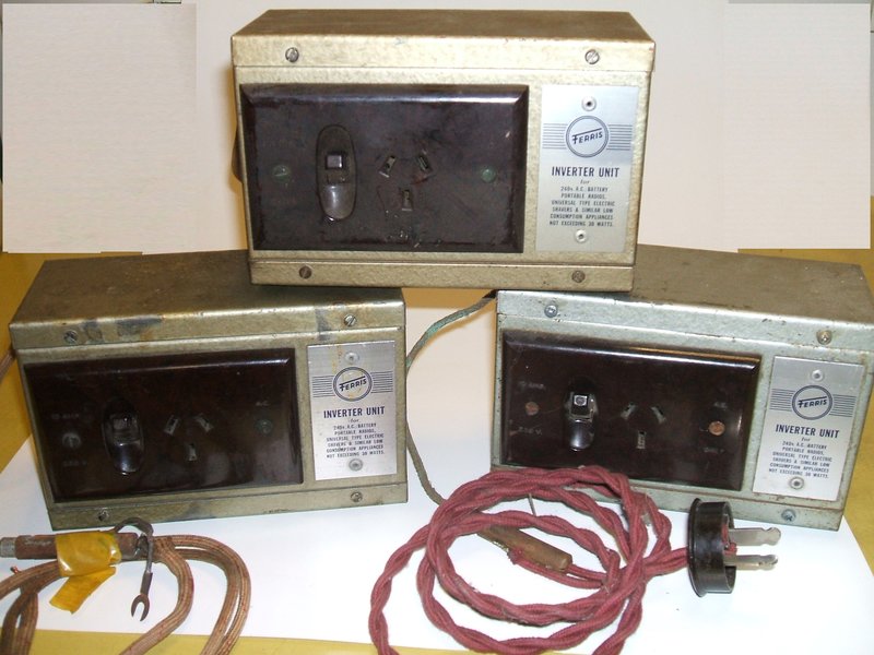
My collection of Ferris inverters. The unit on the right is used on my home lighting plant and is fitted with a two pin polarised plug.
My collection of Ferris inverters. The unit on the right is used
on my home lighting plant and is fitted with a two pin polarised plug.
Ferris are most well known for a series of portable car radios; radios which could operate off the car electrical system, but then be taken out of the car and used at home on the mains supply. These radios had brackets to mount them in the car, and had a battery input connection, as well as a connection for 240V AC. The first, and best known of these was the post-war model 74. However, a much later set was actually a conventional mains/ dry battery portable, which was also designed to be used in a car by virtue of the extensive shielding and a socket to connect the set to a car aerial. This was the model 106 which is described here. So that the dry batteries in the radio did not have to be used in the car, a companion 240V AC inverter was available. The M106 would be plugged into this just the way it would be at home.
The Inverter.
It was available for 6,12, or 32V supplies.
32V was of course a common home lighting plant voltage, while 6 and 12V
models were available for car use. The inverter design is completely conventional,
using a 6 pin MSP/Oak non
synchronous vibrator. Output power rating is 240V 30W. Because of the
vibrator type used, the output frequency is 100c/s. This increase in frequency
is acceptable for the small valve radios intended to be used, because if
anything, their power transformer will operate more efficiently, as will
the B+ filtering circuit. Of course, resistive loads such as soldering
irons and incandescent lamps do not care about supply frequency.
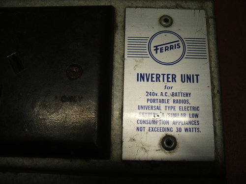
Front panel details.
The inverter is constructed in a steel
box with a conventional flush mounted power point on the front. The power
point has been modified so that the switch controls the DC input. For all
practical purposes, using the inverter is just like plugging in an appliance
at home. While it was introduced to power the 106, the inverter is advertised
as being suitable for certain other appliances up to 30W.
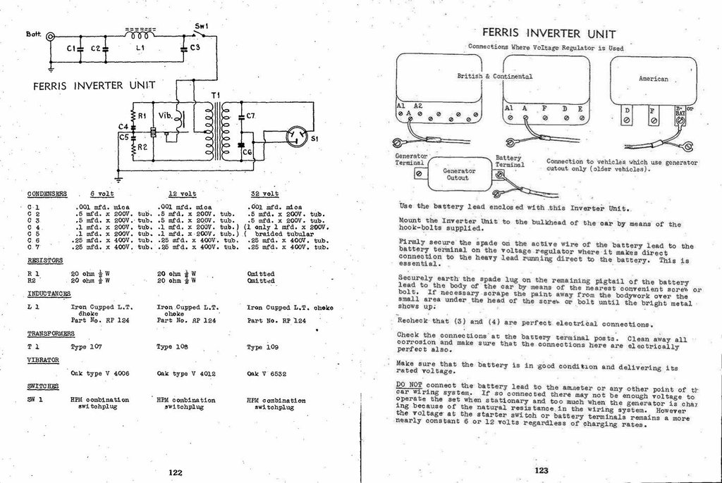
The battery cable is screened and includes
a shielded fuse holder. C1 and C2 provide input filtering, along with L1
and C3.
R1, R2, C4, and C5 provide RFI suppression
for the vibrator contacts. C4 and C5 are 0.1uF. The 20R series resistors
limit the capacitor discharge current when the vibrator contacts make,
otherwise the capacitors would simply be shorted out having just been fully
charged. A sudden discharge current would flow causing RFI.
C6 and C7 , each 0.25uF, make up the buffer
capacitance, being 0.125uF in total. The output is balanced, with the common
connection of the two buffer capacitors earthed. The 106 radio has a three
core power cable, so that when plugged into the inverter, the radio is
earthed to the car body.
The circuit for the three different voltages
is essentially the same, with the main difference being the transformer
primary voltage, and the vibrator driving coil voltage being altered to
suit.
However, for the 32V model, some of the
buffer capacitance is connected across the primary winding. In this model,
there is also a 1uF primary buffer, and the components C4, C5, R1 and R2
are omitted. With the higher input voltage, it becomes practical to include
buffer capacitance across the primary, which is actually the most desirable
location because imperfect primary to secondary coupling does not interfere
with correct buffer operation.
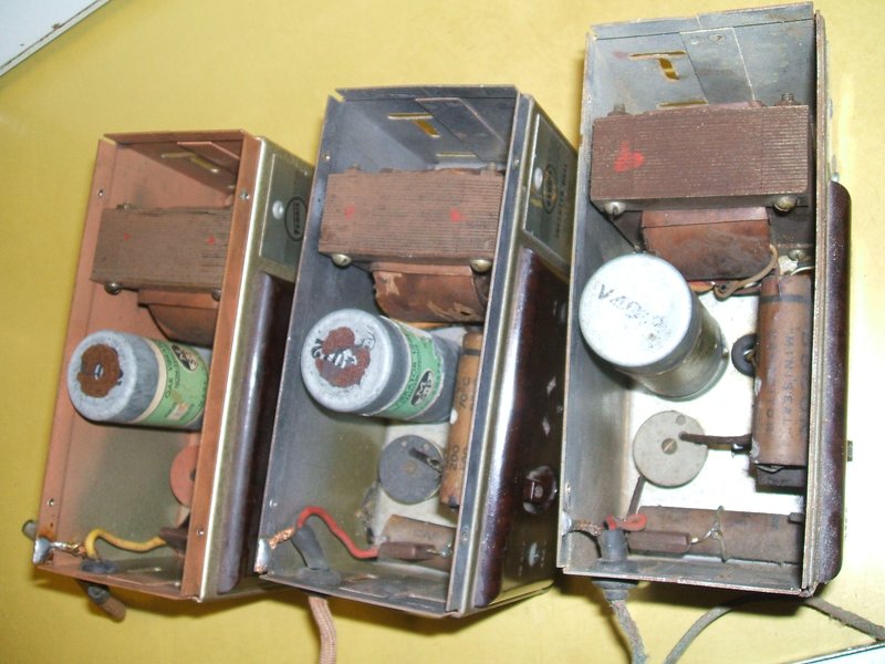
Here we can see the transformer, vibrator, and DC input filtering
components.
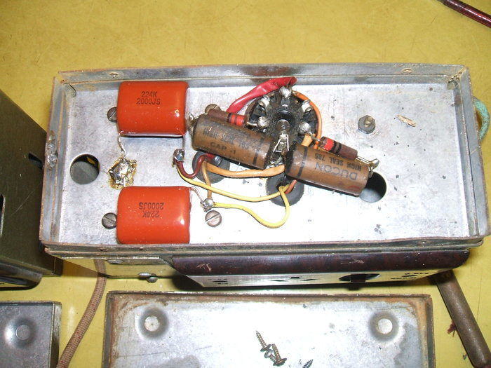
This inverter has been restored and is in regular use. 0.22uF 2000V
polyester capacitors were used to replace C6 & C7.
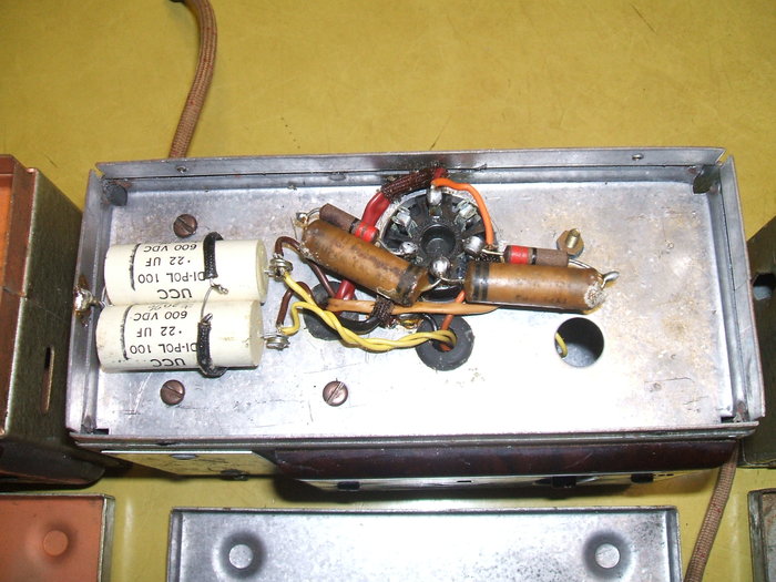
This one has also been restored, but is is missing the fuse holder
and battery cable.
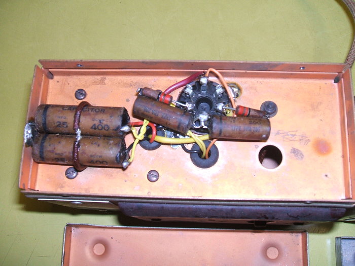
Interestingly, this inverter has been copper plated while the others
are not. As can be seen, the buffer capacitors are original. They will
have to be replaced before use.
Restoration.
I found two of these inverters at car
swap meets, and the third came from the Wyong amateur radio swap. I paid
between $5 and $20 for them. All three are 12V models and use a V4012 vibrator.
Restoration is very easy. Basically all
that needs doing is to replace the 0.25uF buffer capacitors and cleaning
the vibrator contacts if necessary. See
the vibrator notes here. The primary capacitors do not need replacement
as any leakage cannot cause harm. Depending on how the inverter is to be
used, a suitable power lead and plug may need to be attached. For the unit
I have in use, a I fitted it with period cloth covered twisted flex and
a bakelite two pin plug for the house 12V supply. It is most important
to see that the supply is fused. The value of this fuse is not specified,
but 5A is a suitable choice for the 12V model.
Performance.
Provided the 12V supply is earthed, RFI
is a non issue. For the last 14 years, I have been using one of these inverters
to power a Breville portable valve radio with a clip-on mains power supply.
This power supply was designed for the radio and uses a 6X5 rectifier for
the 90V B+ and a selenium recitifier for the 1.5V A supply.
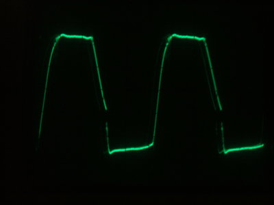
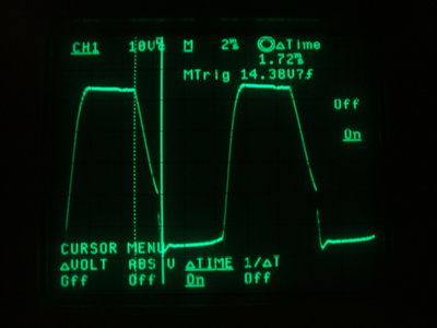
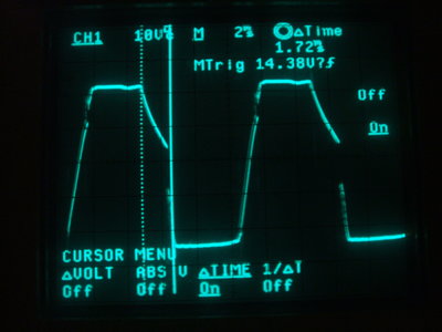
No load. The second waveform shows vibrator dead time.
Waveforms were taken from across the entire
transformer primary. This is the standard method. Of course, the 12V supply
to the inverter must be floating because the CRO has one side of its input
earthed. The voltage at the pins of the 12V plug was kept at 12.6V for
the tests.
The no load waveform is of the correct
shape, with sufficient but not excessive buffer capacitance. Note that
the dead time of the vibrator is about 1.72ms. It should be closer to 1ms.
However, given the inverter has been operating a radio over the last 14
years, this is acceptable wear and would only require a slight adjustment.
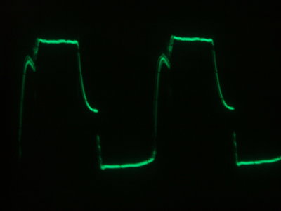
From left to right: 15W load, 30W load, 11W CFL.
Under load, the waveforms are also as expected.
A resistive load of incandescent lamps were used. The waveform shapes for
both 15W and 30W loading are identical, although the amplitude is of course
higher at the lower loading. It can be seen that for AC inverters, a resistive
load discharges the buffer capacitance very quickly during the vibrator
dead time.
The result is the buffer capacitance actually
has little effect. Under these conditions, it is the loading of the inverter
that prevent the destructive high voltage overshoots, which would otherwise
occur with no, or insufficient, buffer capacitance. So, either way there
is no contact sparking. However, a problem is that the buffer capacitor
now is no longer able to reverse the transformer primary voltage at the
correct point, meaning the vibrator contacts now carry the full current
when they open and close. With a properly operating buffer circuit, the
primary current flows just after the contacts close, not when they're starting
to close. This is obviously kinder to the contacts. From this, it can be
imagined that an AC inverter will have a shorter life from the vibrator
compared to a DC-DC converter. That may well be, but as this particular
inverter has been regularly operating a valve radio for 14 years, it serves
as an interesting life test. I think we can say all is well, and in practice
it isn't something to worry too much about!
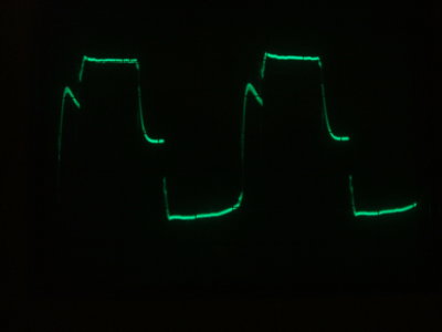
The third waveform is with the inverter powering a Philips 11W compact fluorescent lamp. Here, the mains input is rectified inside the lamp to create a DC supply of the mains voltage peak. As a result of this, the inverter is actually operating along the lines of a DC-DC converter, as is the usual situation with a vibrator supply in a radio. The buffer capacitor works properly therefore. However, notice the slope is actually steeper and for a shorter time than the unloaded waveform. This is indicitave off too much buffer capacitance. It could well be there is a mains filter capacitor across the AC input of the lamp, adding to the buffer capacitance.
It should be obvious from all these waveforms that the type of load has a considerable effect on the operation of a vibrator inverter, and some loads will in theory cause a shorter vibrator life than others. It is not sufficient just to state, for example, "30W maximum loading" and to assume any appliance of less than 30W is suitable.
Furthermore, as the output is a square
wave and at 100c/s, not all appliances are suitable, even if they are 30W
or less. Resistive loads such as incandescent lamps or soldering irons
are ideal, as are switch mode power supplies, such as USB and phone chargers.
These rectify the mains input so only draw current at the peaks of the
voltage. Compact fluorescent lamps of the electronic ballast type are also
usually suitable loads as these rectify the incoming mains.
Some LED lamps or other devices that incorporate
a capacitive dropper should not be used because they present a low, leading
power factor, which adds to the buffer capacitance of the inverter output.
This is harmful to the vibrator. Also, the reactance of the dropper capacitor
will be much less on 100c/s, causing a much greater current to flow than
at 50c/s.
Likewise, inductive loads are unsuitable
because connecting these effectively subtracts from the ideal buffer capacitance.
Also, such loads like induction motors and fluorescent lamps with iron
cored chokes are frequency dependent, and will not function correctly at
the higher frequency.
In short, the load should be kept to incandescent
lamps, soldering irons, small valve radios, and solid state electronic
devices.
| Load | Input Current 12.6V | Output Voltage |
| No load | 420mA | 273V |
| 15W incandescent | 1.7A | 238V |
| 30W incandescent | 2.85A | 207V |
| 11W CFL | 1.3A | 246V |
The above table shows the various output voltages with different loads. Regulation is not perfect of course, and no doubt the connecting leads, fuse holder, and fuse would all contribute to resistance in the supply line. Nevertheless, results are very good for this type of inverter. Note the excellent efficiency.
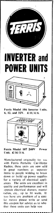
This ad appeared in RTV&H for November 1957. It appears
Ferris was getting rid of excess stock, which would not be surprising given
that transistor portables were starting to appear, making valve portables
obsolete.