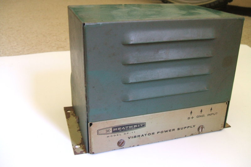
The Heathkit GP-11 was another in the line
of modular vibrator power supplies, except it was available in kit form.
It was also of the last generation of DC-DC vibrator power supplies.
The manual is dated 1961, and unlike Heatkit's
earlier VP-1-12 and VP-1-6 vibrator power supplies, the GP-11 uses silicon
rectifiers.
Like the other American vibrator power
supplies described on this site, this particular example was purchased
on eBay. Given the cult following of Heathkit, there was more bidding compared
to other vibrator equipment I've bought. Nevertheless, I only paid $27
Aussie for it.
Heathkit's vibrator power supplies were designed to be used with their CB and amateur band transceiver kits, but of course were also suitable for all the usual applications. Indeed, the power supply arrived in a Heathkit box which once contained a CB-1, 27 MHz transceiver kit. Also inside the box were two microphones, and AC power cables for the CB-1, and a few other small parts. Given that the GP-11 had a power cable connected to it with the octal socket used for the CB-1 power input, it would be safe to say this is what it powered.
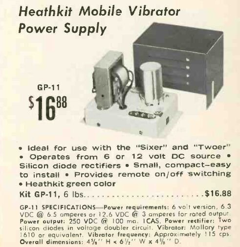
From the Heathkit 1966 catalog.
Features.
The GP-11 has the convenient feature of
being suitable for both 6 and 12 volt inputs. Output is 250V at 100mA.
However, that 100mA is an intermittent rating defined as "Intermittent
Commercial or Amateur Service". When used with a transceiver, it is only
during transmissions that full current is drawn from the power supply;
most of the time the transceiver is in receive mode, drawing less current.
Judging from the design, I would estimate
the continuous current rating to be about 70mA.
By 1961, silicon rectifier technology
was well established, and it was obviously more efficient to use solid
state diodes than a valve rectifier. The power supply also runs cooler
which is all to the good. While a synchronous vibrator would provide the
same efficiency as using silicon diodes, one loses the convenience of a
non polarised input, unless a reversible type is used. Besides, synchronous
vibrators were no longer popular by this time.
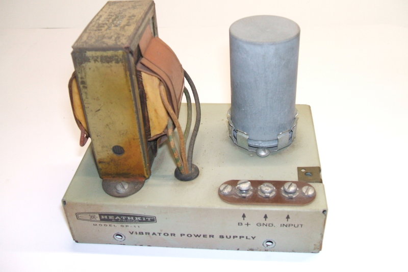
Input and output connections are conveniently made to the terminal
strip on the chassis.
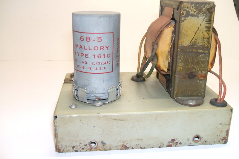
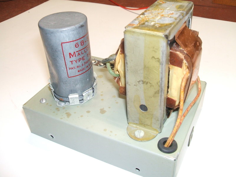
The vibrator is a Mallory 1610, which is of their last generation.
Despite all four pins of the vibrator socket
being used, the Mallory 1610 is in fact a shunt drive type. How it differs
from the conventional kind is that the connection to the drive coil, that
would normally go to one of the contacts (pin 2), comes out to pin 4. The
1610 driving coil suits 6V circuits, but by connecting a resistor in series,
it can also be used on 12V.
Thus, we see a 43R resistor in series
with the drive coil when the circuit is wired for 12V operation. For 6V,
the 43R is bridged out and the vibrator works in the conventional way.
It is interesting to note that an "ordinary"
four pin shunt driver vibrator could be used as a direct plug in replacement
with no modification. The reed connects to pin 1 and the contacts are pins
2 and 3, and so the vibrator would function. Pin 4 is not connected, so
the 43R (or bridging link) would have no effect. Of course, the vibrator
has to be a 12V type if the GP-11 is wired for 12V. And, as mentioned previously,
the reed (pin 1) must not connect to the can, but this seems to
be the situation for most four pin shunt drive types.
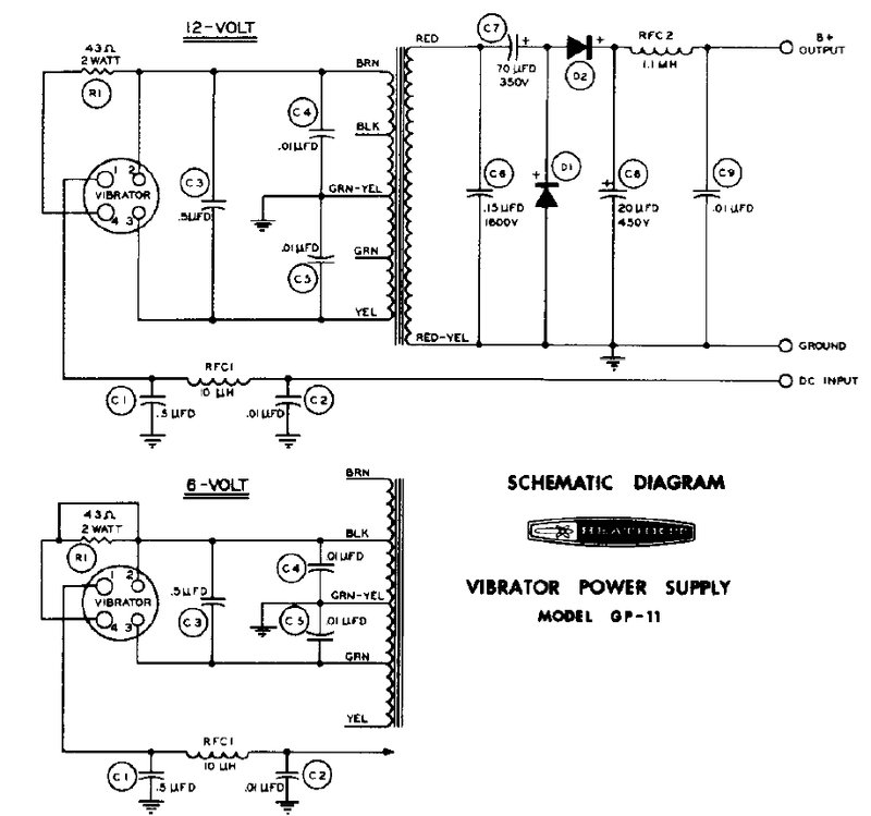
Aside from bridging, or not bridging, the driving coil series resistor, the other step taken to convert from 6V to 12V (or vice versa) is to connect the vibrator contacts to the appropriate transformer primary tappings.
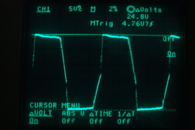
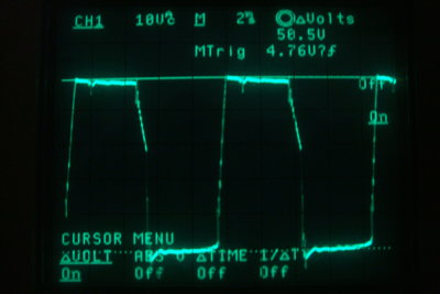
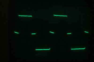
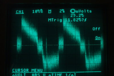
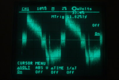
These waveforms are taken across the vibrator contacts for 6V operation
(left), and 12V operation (right). Effective buffer capacitance is increased
when 12V operation is implemented.
Interestingly, this is another vibrator circuit in which the primary centre tap is earthed and the vibrator reed switches the 12V supply to either side of the primary winding. This seems to be a not uncommon practice with DC-AC inverters, but this is the first time I've seen it used in a radio type circuit. Electrically, of course, it is the same as the conventional circuit, where the supply is fed to the centre tap, and either side is switched to earth. However, it would preclude the use of a vibrator where the reed connection is connected to the can.
The usual RFI suppression components are fitted. The DC input feeds the vibrator via a pi filter comprised of a .01uF ceramic condenser, a 10uH choke, and a .5uF paper condenser. Two additional .01uF ceramic condensers bypass the vibrator contacts. Across the primary is a .5uF paper condenser. Its value is too low to have a significant effect on transformer tuning, especially for 6V operation, and primarily functions as an RF suppressor. A condenser here does cause some ringing, but this is harmless. If desired, the ringing can be reduced by connecting a damping resistor in series with the condenser.
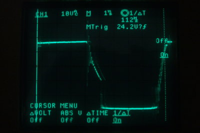
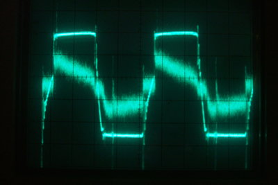
Note the ringing on the downward slope caused by the .5uF primary
condenser. This ringing becomes visible when the power supply is loaded;
in this case with a 15W light bulb. Note the 112 Hz operating frequency.
Across the secondary of the transformer
is the usual buffer condenser; the purpose of which tunes the transformer,
so that when the contacts open and close the voltage across them is at
a minimum, and therefore no sparking occurs. Surprisingly, in the description
of operation, the manual makes absolutely no reference to this component.
The .15uF value is higher than usually
seen in a radio type circuit, but here the transformer secondary is only
130V. In the more common circuit, where the condenser is connected across
a 500V winding (250-0-250V), the value is smaller by the square of the
turns ratio.
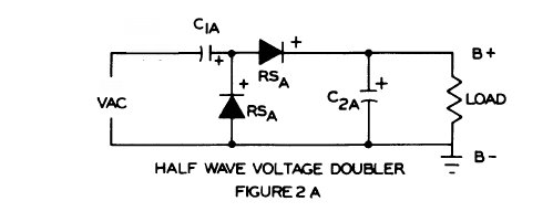
Rectification is by means of a voltage doubling rectifier. This scheme has the advantage of requiring half the number of secondary turns than if a bridge rectifier was used, or a quarter of the number of turns, if a full wave centre tap rectifier was used (such as a valve or contacts of a synchronous vibrator). Furthermore, a low secondary voltage means much less stress on the buffer condenser, and less insulation stress with the transformer.
Somewhat strangely, the voltage doubler is a half wave type. This is not the best way to load a vibrator as the the current draw on the positive and negative peaks is not even. The use of this type of doubler is something that intrigued about the GP-11, and was one reason I wanted to obtain one, so I could investigate its performance..
B+ RF filtering is achieved by a 1.1mH RF choke and .01uF ceramic condenser. Additional filtering for DC ripple is likely to be required in the equipment powered, especially if it is RF or audio related.
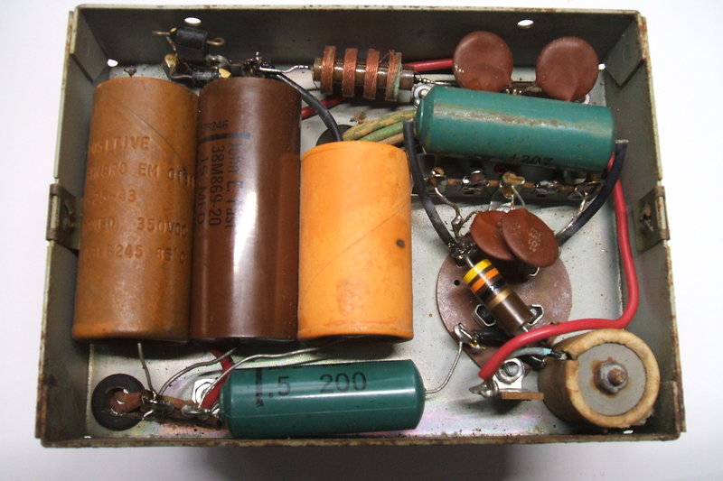
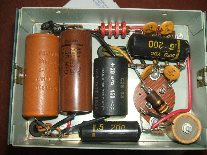
Under the chassis. Note the 1.1mH RF choke at the top. Some corrosion
is visible. The .15uF buffer is between the two electrolytics.
Internally, the construction had a professional
finish, so either a very experienced constructor assembled it, or it was
pre-assembled by Heathkit. The first thing to do was reform the two electrolytic
condensers. To do this, I removed the vibrator and connected AC from a
14V transformer, via a 36W light bulb, to the primary connections of the
transformer in the GP-11. The 14V transformer was fed from a Variac. The
DC output was monitored, and over several hours the voltage increased,
while at the same time the primary current dropped, as evident by dimming
of the bulb.
Eventually, the voltage stabilised with
no further increase. This indicated reforming was now complete. Just to
check the condensers had sufficient capacity, a 240V 15W bulb was connected
across the DC output. It lit up as it should.
At this point I discovered the 1.1mH RF
choke was open circuit. A closer look revealed green corrosion at both
ends of the winding. This, and the corroded bottom plate made me wonder
if this GP-11 had been used in a marine environment. Anyway, one end of
the choke was easily fixed by peeling off the few turns of corroded wire
and re-terminating it.
Because of the direction of the winding,
dealing with the other end was not so simple. Not being able to rewind
a honeycomb winding, I simply bypassed the corroded winding.
There are four pie sections in this choke.
Now there are only three in circuit. For this application, the reduction
in inductance is trivial.
The buffer condenser is interesting. It
is oil filled. That no doubt means it's also a paper type. The physical
size is unusually large, but then I noted the 1600V rating. Such a voltage
rating is normally used with 500V C.T. type secondaries, and is overkill
with only 130V. My guess is that whoever designed the GP-11 had it drummed
into his head that buffer condensers must always be at least 1600V, without
thinking about the operating conditions of this particular circuit.
However, it does mean that working well
under its rated voltage, it will be more reliable. During my tests, it
did not get warm at all. I did notice some of the oil has leaked out -
it was visible on the side of one of the electrolytics.
With the secondary circuit all happy, it was time to turn to the vibrator. Not surprisingly, the contacts had insulating film built up on them from years of disuse. Seeing as the drive coil could be run isolated from the contacts, I took a lazy way out to get the vibrator working. I connected the drive coil to a function generator and fed it with a square wave. Despite the rated operating frequency being around 115 Hz, I found the reed vibrated best at 46 Hz. Across the contacts I connected a 30V current limited bench supply. Eventually, the film started to burn through as evident by an increase in current. At this point the vibrator could work on its own, so I connected it to my test panel and ran it for several hours to clean the contacts.
Vibrator run into a resistive load to check the contacts.
Results were good and we now had reliable
operation with clean contacts. Now it was time to plug the vibrator back
into the GP-11 and power it up.
I don't know why, but silly me had just
assumed it had been wired for 12V operation. Well, the 15W bulb used for
the DC load lit up much brighter than it should! Sure enough when I looked
closely, the 43R had a bridging wire across it which confirmed it was 6V.
On 6V operation it worked as it should, with 276V into the 240V 15W (60mA)
bulb, with the input at 6.3V.
As I already have two 6V-only vibrator
power supplies, I felt it would be much more useful to convert the GP-11
to 12V. The bridging wire across the 43R was removed, and the transformer
tappings changed over to 12V. With an input of 12.6V, the output was 281V
into the 15W bulb.
As shown previously, I took waveforms
across the primary for both voltages, as I was curious to see if changing
the tappings had any effect on the effective buffer capacitance. It does
indeed look as though that the buffer capacitance is more than necessary
when set up for 12V. However, the .5uF is now across the entire primary
and it will have more of an effect.
Meanwhile, no problems were caused by the original buffer condenser, so I have left it in situ. If I should put this supply into normal use, I will investigate its condition further. Chances are that it could be left in use, operating at a fraction of its voltage. With a plastic case and immersed in oil, moisture entry should be less of a problem than the cheap wax dipped types.
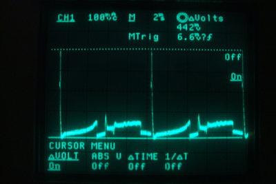
This shows the primary current with no loading. The high amplitude
spikes are caused by the buffer condenser charging. Current here is about
4.4A peak. Increasing the buffer capacitance increases this substantially,
which is one reason it is not desirable to use more buffer capacitance
than required.
More importantly, it is undesirable with vibrator circuits because it causes an unbalanced operation. According to vibrator literature, this causes transfer of contact material and eventual pitting and locking together of contacts. Evidently, Heathkit did not consult with Mallory during the design work.
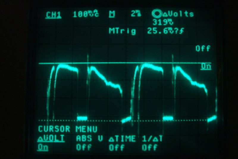
I measured the current waveform at the
doubler input; i.e., in series with the 70uF condenser. As suspected, the
loading was asymmetrical.
On the negative cycle peak current is 292mA (charging the 70uF),
and on the positive peak it's 334mA (charging the 20uF and powering the
load). Third waveform shows the timing relative to the primary voltage.
This shows the primary current when the GP-11 was loaded with the
15W bulb. Note the asymmetrical waveform. No current flow occurs when the
reed is between contacts. Note that every second "dead" period has a slope.
This is because the driving coil is in circuit at this point.
What had me curious is why Heathkit did not use a full wave doubler. There would be no difference in cost as there are still two diodes and two condensers, and the transformer secondary does not need one side earthed.
With the full wave, or symmetrical voltage doubler, there are effectively two half wave rectified supplies in series. We can see that the upper diode and C1B forms a simple half wave supply, with C1B charging to the peak of the input voltage on the positive cycle. Likewise, the lower diode and C2B form another half wave supply, and C2B charges only on the negative cycle. Because the positive and negative supply are connected in series, thus doubling the peak of the input voltage, the current they both provide is the same. Therefore, the input current is symmetrical. Output ripple is twice the supply frequency (which is easier to filter), and regulation is improved.
Seeing as it was a simple matter to try out, I connected a couple of 1N4007 diodes and 47uF 350V electrolytics together in a full wave doubling circuit. I disconnected the existing half wave doubler and patched in my experimental circuit. Not surprisingly, we now had a much better input current waveform:
It would be tempting to convert the GP-11 to the full wave circuit, but I am loathe to modify commercially made circuits. It wouldn't be a proper GP-11 then! Certainly, if one is building a new vibrator power supply, the full wave circuit should be used for best vibrator operating conditions.
The GP-11 is shown powering a 240V 15W incandescent bulb from a
12V DC supply.
My overall impression of the GP-11 is it's
a nicely designed unit. It's very compact and efficient. The design of
the 1610 vibrator is such that no mechanical vibration is evident; only
the buzzing sound. Had silicon diodes been available in the days of valve
car radios, it's fairly certain to say they would have been used, and in
doubling type rectifier circuits.
By the time the GP-11 was developed, it
was only two way radio equipment that was still using DC-DC vibrator power
supplies (in the U.S.).
My main criticism is that the rectifier
is half wave, where with the same components, a full wave circuit could
have been used. Another criticism is the lack of a fuse. While the manual
shows how to connect a fuse in the supply line, you can bet most users
didn't bother. It would have been a simple matter to include a 3AG fuse
mounted on the chassis of the GP-11. I might seem to have an obsession
with fusing vibrator power supplies, but we must remember that vibrator
transformers, and vibrators are no longer made.
This second GP-11 appeared to never have been used.
This second unit was purchased because of the excellent cosmetic condition it looked to be in. Luckily, the eBay seller agreed to post to Australia. I always appreciate it when U.S. eBay members will do that. The postage cost was quite high, but these days that's unavoidable.
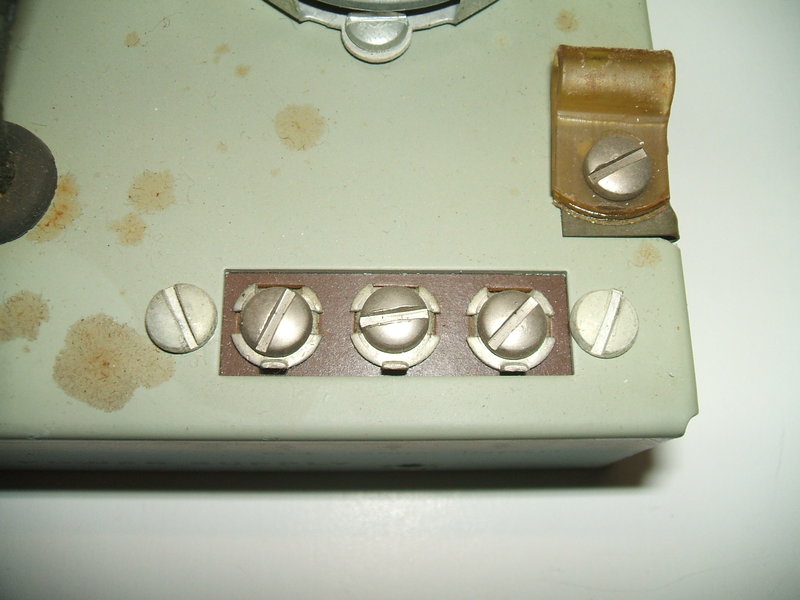
Terminal strip on wrong side of chassis. The possibility of a short
circuit is obvious.
Upon receiving it a couple of weeks later, I observed that it looked as though it had never been used. It had been very well constructed, but one thing stood out, and that was the terminal strip. The terminals were ever so close to short circuiting against the chassis. It was surprising to see this, and when I checked with my other GP-11, it was obvious what the problem was - the terminal strip should be above the chassis, not below it. On that basis, I suspect this unit was constructed as a kit and not commercially made up. Despite that, the construction was perfect and the soldering was of factory quality.
It was a simple matter to replace the terminal strip on the top side of the chassis. It was noticed the vibrator can had dents in it, and also a curious dent in the cover for the power supply - which looked like it was from the transformer. My guess is that all the parts were stored inside the lid before construction, and it was dropped. Looking at the eBay ad more closely, I could see that both the vibrator and lid dents were there before, so it was nothing to do with postage.
Unlike the first unit, this one had only been made for 12V.
Some of the condensers are of a different style to the first unit.
Getting it going was straightforward. After
my experience with the first unit, I didn't bother replacing any condensers.
Of course, the vibrator did not start which was expected, given it's a
shunt drive type. Repeated application of 12V didn't get it going, even
though the reed could be heard to be swinging. Evidently, the back emf
wasn't enough to break down the tungsten oxide on the contacts. With the
vibrator removed from the power supply, I tried with 30V but current limited
to 500mA. It still didn't start. Because I was lazy and didn't want to
get out my high voltage contact cleaning kit, I put the vibrator back in
the power supply and now applied 30V at 500mA to the input. The idea here
was to use the transformer primary inductance to create a higher back emf,
to break down the oxide. It worked virtually straight away. The 500mA limit
on the power supply prevents anything bad happening once the vibrator starts.
Of course, the 30V should not be applied continuously, because at 500mA
this will overheat the drive coil. Rather, it should be done in bursts
until it starts.
Once started, the input current rapidly
dropped as the long disused electrolytic condensers reformed. Idling current
was about 500mA. The waveform was checked and found to be identical to
the first unit. A 15W 240V incandescent bulb caused a draw of 2A on the
12V input. Next, an 11W CFL was tried and it drew 1.5A.
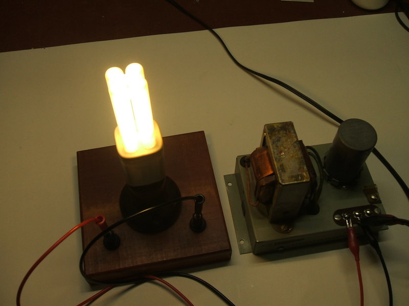
My second Heathkit GP-11 powering a 240V 11W CFL from 12V DC. Input
current is about 1.5A.