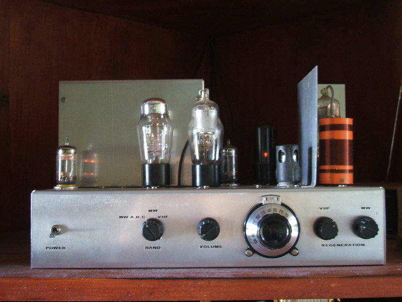
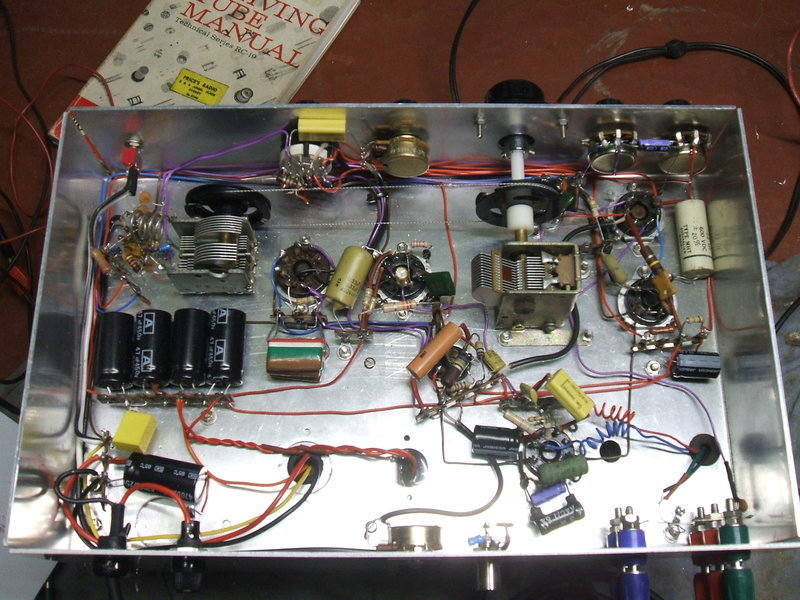
Valves fron left to right: 12AT7, 6H6, 6J7, 12AU7, 6V6, 6AK5, 6J7.
Valves fron left to right: 12AT7, 6H6, 6J7, 12AU7, 6V6, 6AK5, 6J7.
This receiver started its life originally
as a mains operated set using my newly designed 6CM5 audio amplifier circuit,
back in 2006. It is described here.
In 2010, I converted it to run off the
12V house supply. This entailed the mains transformer and rectifier being
replaced by a vibrator power supply, and the 6CM5 amplifier was replaced
with a conventional 6V6 design, in the interest of lower power consumption.
At the end of 2015, automatic regeneration control was installed.
The New Circuit.
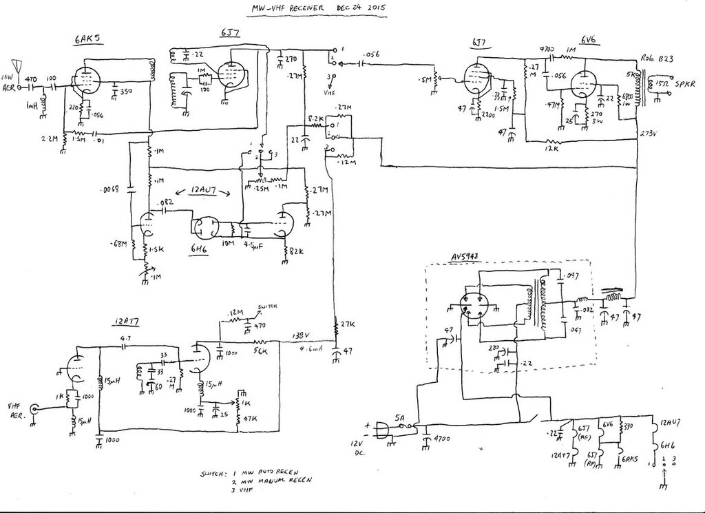
VHF receiver.
This remains unchanged from the original
receiver, and uses the design shown here.
In view of more recent developments, I will eventually replace the 12AT7
cathode choke for the detector with the homemade version which provides
stronger oscillation. The regeneration control will be converted to a rheostat
type, rather than a voltage divider, to provide what is essentially automatic
regeneration control, and I will experiment with increasing the plate load
resistor to obtain higher audio output, as was described here.
MW receiver.
Initially, when the receiver was converted
to 12V, this was left as is. However, with developments with my automatic
regeneration control and future plans to incorporate this, an RF amplifier
was added in 2012. This was done to eliminate aerial loading effects on
the tuned circuit, and makes regeneration adjustment more consistent across
the band. The RF amplifier uses a 6AK5 running at a lot less than its full
plate voltage rating. The input is untuned. It is described here.
The detector, using a 6J7, is unchanged. It's based on that used in the Tiny Tim II circuit. and uses the same coil data. For this circuit, the regeneration is controlled by adjusting the screen grid voltage.
Audio Amplifier.
The original 6J7 voltage amplifier was
left as is, but the 6CM5 and 6CG7 were removed. In their place went a 6V6.
The problem with using a 6CM5 on a battery supply is that it draws 1.2A
heater current, and yet provides no more output power than a "proper" audio
output valve which draws 450-900mA. On a solar supply, I wasn't enthused
about this very poor efficiency, and so a 6V6 was used instead.
This simplified things as the 6CG7 driver
stage was no longer required, saving another 600mA.
Power Supply.
Of course, the most major change in the
conversion was with the power supply itself. The previous mains power transformer
and 5AS4 rectifier were removed, and a vibrator power supply installed.
This uses an MSP/Oak split
reed type, AV5948. It, along with the transformer came from an AWA
Carphone power supply. The split reed aspect is not required in this circuit,
so a normal synchronous type could be used instead. Output is about 270V.
For shielding, both for RF and acoustic
noise, the vibrator supply was mounted on a subchassis and built into a
separate box mounted on the radio chassis. I discovered how critical bypass
condenser earthing is when I built this supply, because moving the earth
point around the sub chassis could make the RFI come and go. The condenrsers
ended up being earthed somewhere near the middle of the sub chassis. It
proves that not all earths are the same! The power supply is completely
interference free.
Among the virtues of series
driven vibrators, power switching can be done by simply switching the
low current reed, rather than the whole vibrator/transformer combination.
This means the radio's power switch only switches the valve heaters and
vibrator reed, so does not have to be of particularly high current.
The valve heaters are wired in series
and series/parallel pairs to enable 12.6V operation.
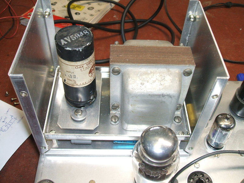
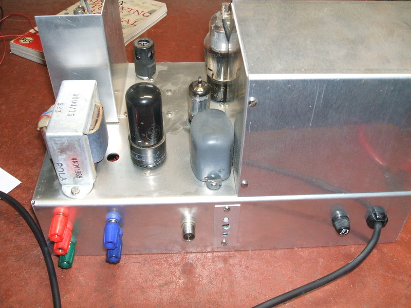
Inside the vibrator power supply. The vibrator socket is mounted
on grommets to reduce acoustic noise.
Adding Automatic Regeneration.
With the success of my automatic regeneration
control circuits described elsewhere, this receiver was an ideal candidate
to have such a circuit installed. Being battery operated, with the batteries
charged from solar panels, there is not surprisingly a considerable fluctuation
with supply voltage. Typically, this might vary from 11V at night to a
little over 14V on a sunny day. A problem with this receiver in its original
12V form was that the regeneration would vary with supply voltage. So,
if the regeneration control was set in the morning before the battery voltage
increased, by afternoon it would be too much. Thus, the regeneration control
was having to be frequently reset.
I had given considerable thought as to
which of my two ARC circuits would suit this receiver. Foremost was avoiding
increasing the current drain by as much as possible. This didn't include
installing solid state diodes either. Also, thought was given as to how
both circuits behave.
The circuit described here
was not considered suitable in its present form because when the regeneration
is switched from manual to automatic, the 1uF condenser does not charge
immediately. In that time the receiver will oscillate and thus be unpleasant
to listen to. This circuit is best suited to a receiver where there is
no manual control.
So, it was decided to use the one described
here.
One of the valves would have to be a double diode such as a 6AL5 or 6H6.
This meant having an extra 300mA heater consumption, and would allow another
300mA valve heater to be connected in series. Any more valves and I'd be
uncomfortable about power consumption. As it is, the ARC circuit requires
three extra triodes as well as the double diode.
One of the triodes is the screen grid
control, and the other two are simply to obtain sufficient audio voltage
to operate the circuit.
If the extra valve was to be a 12AX7,
there is still one triode's worth of gain short. I solved this one by reflexing.
A further refinement to the circuit would be to switch off the 12AX7 and
6AL5 heaters when the regeneration was set to manual, so the radio could
be run on minimum power if necessary.
Because I had one and it looked pretty,
I used a glass G style 6H6 for the double diode. Initially I used a 12AX7
for the control valve, but found that contact potential was problematic
because of the high value of grid resistor, so changed it for a 12AU7.
The option of external audio input was
deleted as I'd never used this in the original receiver. This allowed the
extra switch position to be used for the ARC instead.
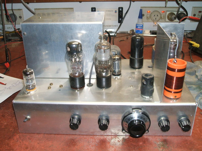
View of receiver before front panel was labelled.
How the Automatic Regeneration Control
works.
The 6AK5 RF amplifier was modified to
function as a reflex amplifier to get the first bit of audio gain. The
audio from the 6J7 plate feeds the grid of the 6AK5 via a voltage divider
consisting of 1.5M and 2.2M resistors. The reason for this attenuation
is that if a reflex amplifier is pushed too far, strange instability issues
arise. As this valve also works as an RF amplifier, grid voltage controls
its gain. So, if the gird voltage is modulated high enough, then the RF
gain will fluctuate also, creating a feedback effect.
For reflex operation, the 100pF aerial
coupling condenser will pass the MW signals, but is not sufficient to bypass
the audio being fed into the grid. The 1mH choke is necessary to provide
a low impedance path to earth, below MW frequencies, otherwise 50c/s hum
enters the 6AK5 grid. The 470pF simply isolates any DC present on the aerial
from damaging the choke (e.g. if the aerial wire was touched to 12V). It
also provides extra high pass filtering.
The 6AK5 functions as a triode as far as
its role as an audio amplifier is concerned. The 100K dropping resistor
then functions as the plate load across which the audio is developed. It
is bypassed with 330pF; sufficient for RF, but not audio.
As the 6AK5 is used here, it has very
useful gain for audio, but the operating conditions mean it is not a hi-fi
amplification stage. Thus, it feeds only the ARC circuit.
From the 6AK5, the amplified audio now proceeds to the next stage, one triode of a 12AU7. The gain of this is adjustable with a cathode rheostat. A conventional volume control arrangement could have been used, but I had lots of preset 100K pots which suit this kind of circuit rather well.
At this point, the audio signal is now
strong enough to be converted to a DC voltage, proportional to the audio
level. The 6H6 is a voltage doubling rectifier which feeds a load consisting
of a 10M and 4.5uF time constant. The audio earth return for the 6H6 is
via the .22uF condenser in the 6J7 screen grid circuit, when the regeneration
control is switched to automatic.
The voltage across the 10M becomes more
negative as the audio level increases. This voltage controls the other
12AU7 triode which simply functions as a voltage controlled resistor. It
can be seen that as the grid to cathode voltage becomes more negative,
the triode conducts less, and less voltage appears across the 82K. As the
voltage across the 82K feeds the 6J7 screen grid, the regeneration is reduced.
If the signal, and therefore the audio, is weak, then the reverse happens
and the triode conducts more, increasing the amount of regeneration.
The condenser in the time constant circuit
is chosen to be just long enough so that ordinary speech and music does
not cause the regeneration voltage to fluctuate. If the time constant is
too long, there is excessive delay in the regeneration adjusting itself
when tuning into another station.
One problem I had was in that using a
12AX7 for the triode valve, I found that the range of control was not as
it should be. This turned out to be because of a permanent negative grid
voltage. Not surprisingly, because of the 10M resistor, contact potential
was creating an intial bias. Useful for an audio amplifier, but not here.
As the 12AU7 has a lower gain, I assumed this would be less of a problem,
and so it turned out to be. Presumably, the different operating conditions
of the 6J7 against the 6BL8 in the original circuit account for the 12AX7
being successful there, but not in this circuit.
ARC Lockout.
The next problem took more experimenting
to deal with. As mentioned in the other articles about ARC, certain detector
valves do not work well with the circuit. This is because when oscillating,
they do not create sufficient audio to actuate the ARC. In effect, the
circuit suffers from ARC lockout. The regeneration voltage keeps rising
and as a result the audio voltage becomes less and less, creating a run
away effect. With valves like 6BX6 and 6BL8, gain is high enough for the
detector to start squegging as soon as it starts oscillating. This provides
a very high audio voltage which immediately throttles the ARC circuit back.
But, the 6J7 does not squeg. I tried a 6SH7 instead, but it too did not
squeg. Interesting, as a 6SH7 in the Minivox
circuit does squeg. I put this down to the difference in aerial coils;
the Minivox having a higher gain commercially made type. So, it appears
the aerial coil design as well as the detector valve type needs to be considered.
The practical effect of this problem was
that when the receiver was switched on, the 12AX7 control triode warmed
up faster than the 6J7, 6AK5, and 6H6 circuit. Regeneration was excessive,
and because of reduced audio, when the other valves did warm up, they couldn't
control it. One temporary way around this was to switch to manual regeneration
and let the 12AX7 cathode cool until the other valves had warmed up. Of
course, that defeats the whole purpose of ARC. Ideas such as relays operating
in the B+ circuit when the other valves had warmed up were contemplated,
but I really wanted to avoid that if possible.
I was able to overcome the problem simply
by restricting the control range of the ARC circuit. And here, the 82K
resistor is most important - it may have to be altered in clones of this
circuit.
Observing the required regeneration voltages
when manually adjusted, it was clear that the maximum 6J7 screen grid voltage
was about 30V; this at the low frequency end of the band. By restricting
the ARC to provide no more than 30V at any time, it meant that the 6J7
still provided enough audio output to activate the ARC under all conditions.
In practice this has worked perfectly.
In the ten months that this receiver has
been in use, not once has it been necessary to use the manual regeneration
control. This includes listening to 2ZB from Wellington NZ at night.
Adjustments.
With the receiver tuned to the low end
of the band (550Kc/s), measure the screen grid of the 6J7 at the .22uF
condenser. Find out what voltage it needs to commence oscillation.
Next, short the plate of the 12AU7 audio
amp (junction of .082uF and 100K) to earth. This deprives the ARC detector
of signal, and will pass maximum current through the control triode of
the 12AU7. Now, alter the 82K if necessary so that the voltage at the .22uF
is the same as what was recorded before.
By this means, it can be seen that the
maximum regeneration voltage is available, but no more.
Finally, a weak station is tuned
in with the receiver set to manual regeneration (I use 2LT which is about
60km distant, but directional away from me). Then the receiver is set to
ARC and the 100K preset adjusted until oscillation just dies away and audio
is clear and free from distortion.
It will then be found that as the receiver
is tuned across the band, the regeneration will adjust itself to each station.
Back of chassis shows terminals and ARC preset. One of the red terminals
is the 6J7 screen grid condenser, and can be connected to a high impedance
meter to show relative signal strength. Panel was labelled after this photo
was taken.
Noise limiter.
During development of this circuit, it
was noticed that a noise limited signal was available at the 12AU7 audio
amp plate. This comes about because of the following 6H6 with its RC load.
The 6H6 draws current on the peaks of the audio as the 4.5uF charges, which
thus clips the signal at this point, and is self adjusting. Due to the
non hi-fi characteristics of the audio at this point, it is not actually
recommended that the signal here be used, but it does illustrate a concept
which I hope to develop further.
Signal strength meter.
As the regeneration level is a function
of audio level, and thus proportional to signal strength, a meter connected
to the .22uF screen grid condenser can show relative signal strength. The
meter needs to have a high resistance of course, otherwise the regeneration
circuit will be excessively loaded. Suitably biassed, it might be possible
to use a magic eye indicator, but with the extra heater current required,
I have not experimented with this. Some success was obtained with a 100uA
moving coil meter in series with the 12AU7 control triode plate, but the
reverse operation looked unnatural. The current increases with weak signals
rather than decreases, requiring some kind of inverting stage to give a
more familiar operation.