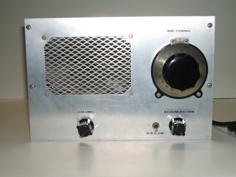
This regenerative receiver adjusts regeneration automatically and thus can be used by anyone; the user only needing to adjust tuning and volume.
This regenerative receiver adjusts regeneration automatically
and thus can be used by anyone; the user only needing to adjust tuning
and volume.
Background.
Regenerative receivers have the advantage
of simplicity with good performance, and for the last 25 or so years have
been a large part of my means for listening to medium wave transmissions.
And, they are probably one of my most built projects. However, while this
is all very well with someone who understands the principles of regeneration,
and more importantly, how to control it, the problem is with non technical
operators.
Briefly, the concept of a regenerative
receiver is to cause a controlled amount of positive feedback in a tuned
circuit which increases gain and Q considerably. The tuned circuit may
be part of an RF amplifier or the detector. Regeneration makes it possible
with just one tuned circuit to obtain sensitivity and selectivity similar
to a superhet. Having said that, there are plenty of poor designs around
that give regenerative receivers a bad name.
The key to obtaining optimum performance
is in the amount of feedback. Too little, and sensitivity is poor; too
much and oscillation occurs which obliterates the signal. The level of
feedback must be adjusted to the point just before oscillation occurs.
So, regenerative receivers have a control for this adjustment.
Because the performance of the tuned circuit
varies across the band, it means that the regeneration has to be adjusted
each time another station is tuned in.
These variations are caused by such things
as aerial loading and the LC ratio of the tuned circuit. Furthermore, supply
voltage variations will affect the level of feedback.
Experience has shown it is impossible
for non technical users to optimally adjust regeneration controls, with
the results invariably being frustrating squeals emanating from the receiver.
This is one reason regenerative receivers
were quickly replaced with TRF's and superhets in the late 1920's
and early 1930's. After this, they were relegated to the realms of the
technically minded constructor, with many magazine projects right through
to the end of the valve era, by which time building radios at home was
a declining hobby.
Regenerative receiver
improvements.
First, it needs to be pointed out that
the basic regenerative receiver can be improved to lessen the amount of
regeneration adjustment required.
To eliminate aerial loading effects, a
simple RF amplifier can be placed between the aerial and tuned circuit
where feedback takes place. The B+ supply can be regulated to eliminate
changes in battery or mains voltage affecting regeneration. However, regeneration
still has to be adjusted as the receiver is tuned from one end of the band
to the other because of the LC ratio. My thoughts were, if a human can
know where to set the control, then why not some kind of electronic circuit
doing the adjustment instead?
Fortuitous construction
mistake.
The first regenerative receiver I built
was during 1984, based on an Electronics Australia design (Three Band Three).
It used a 6BL8 pentode as a regenerative detector, the triode being a following
audio amplifier to drive a speaker or headphones. Beyond this point, I
deviated from their circuit and used a 6BM8 for audio output instead of
a 6AQ5. I didn't realise it until many years after, but an accidental misreading
of a capacitor value during construction made the circuit perform slightly
different to that, had I used the correct value.
And, it was because of this I could see
how regeneration could be made automatic.
Instead of using 100pF for the grid capacitor,
I had used 1000pF. In as far as general performance went, it didn't make
a lot of difference. Regeneration was as smooth as it should be, the sound
was good, and sensitivity down to the noise level. What happened when the
regeneration control was advanced further than it should be, was another
thing. In normal regenerative receivers, RF oscillation occurs and a beat
is heard against station carriers, as the receiver is tuned across the
band. Between stations, not a lot is heard. If the receiver is oscillating
and tuned right on the carrier, a form of direct conversion occurs, and
it isn't always evident the detector is oscillating.
Because of the increase in grid capacitor
value in my set, and that a high gain TV valve was being used as the detector,
what happened as well was a fierce audio oscillation. This was simply because
of the grid time constant increased to the point where the detector was
squegging at an audio rate.
So, to sum up, a loud whistle was heard
if the regeneration was advanced beyond the optimum point, whether a station
was tuned or not.
The concept of automatic
regeneration control.
The whistle was far louder than the ordinary
program level, so it seemed to me that if one was to rectify it, then a
DC voltage would be produced in proportion. As the whistle got louder,
then the DC would increase, and vice versa. The increasing level of DC
could then be used to back off the regeneration.
In early 1985 I started experimenting.
To get DC proportional to the whistle level just entailed a germanium diode
and filter capacitor, taking signal from the audio amp before the volume
control. How to control the regeneration with DC? Well, one could do as
in any voltage controlled amplifier and feed the negative going DC into
the grid of the detector, via a high value resistor so as not to shunt
the RF to earth. A control of sorts was indeed possible, but it wasn't
as good as I'd have liked. Looking back I can easily see why - the grid
to cathode circuit is used as a diode in a grid leak detector. By negatively
biassing the grid, while stage gain is reduced, the characteristics of
the 'diode' are altered. In other words, distortion occurs because only
the peaks of the signal are detected.
Regeneration is normally controlled by
adjusting the screen grid of the 6BL8 pentode. Taking it towards earth
reduces regeneration. We could take it to earth via a transistor of which
the base is fed with positive current dependent on the audio level. And
that's what I did. Results were very good and I used the circuit for quite
some time.
One reason for developing the ARC was
because I was developing a car radio using the 6BL8 regenerative circuit,
and I wanted to eliminate the necessity for regeneration adjustment by
the non technical users. Certainly, the prototype receiver worked brilliantly
for mobile use. In fact, the ARC operating also as a form of audio derived
AGC meant that volume was fairly constant as the car was driven through
areas of fluctuating signal strength.
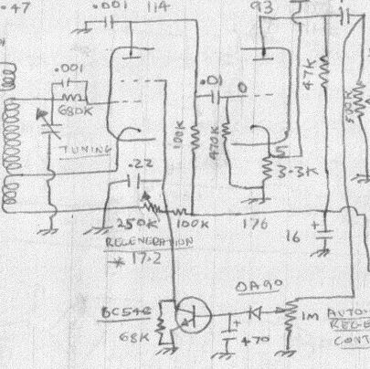
Taken from my original regenerative receiver, this circuit shows
the concept fairly clearly. Excess audio levels (such as when the receiver
has gone into oscillation) cause the transistor to conduct and reduce the
screen voltage. The valve type is 6BL8/ECF80. Note that although it worked,
operating conditions are not optimal. It can be seen that if the ARC pot
is wound all the way up that the postive going audio will be clipped. Also,
the time constant is rather crude relying on transistor bias current draw
to discharge the 470uF capacitor. For mobile use this receiver was fitted
with an RF amplifier and a vibrator power supply.
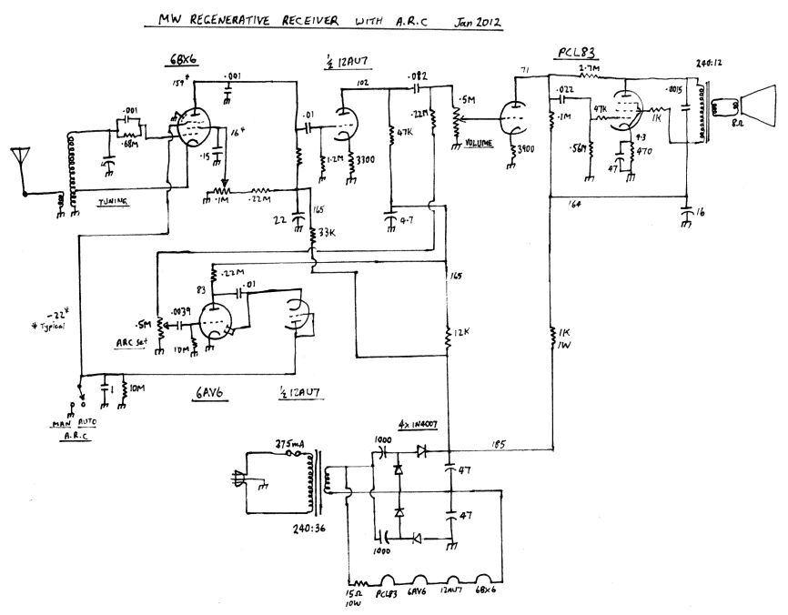
The latest regenerative receiver with ARC. (The 6BX6 plate load
resistor is 100K).
Controlling Regeneration
with DC.
Where a triode is used for the detector,
the plate supply can be varied, or in the case of a pentode, the screen
(g2) voltage. Previously, this was done by a BC548 transistor. To use a
valve is rather problematic though. The problem is that the voltage needs
to be taken quite low - around 15 to 20V is typical. It is difficult to
get the plate voltage of a controlling valve that low using normal valves.
One could take the cathode to a negative voltage so the controlling valve
still can have a fairly high plate to cathode voltage, but it means a negative
supply has to be available.
As stated before, the control grid (g1)
cannot be used for control as it functions as the detector diode. What
about the suppressor grid (g3)? That would not affect the diode performance
at all, and by taking it negative should reduce the gain of the detector
valve. Taking it negative would also mean no current would be required,
just voltage. This was all theory at this point.
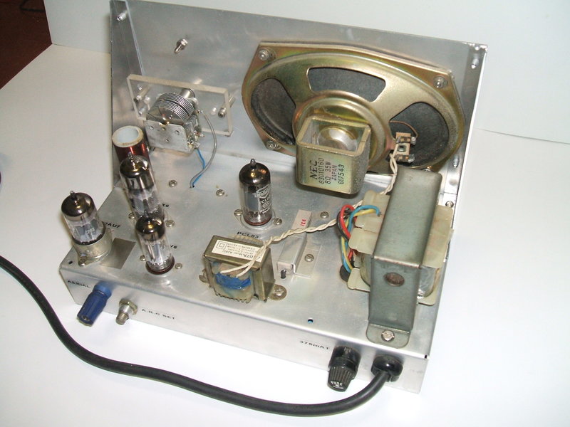
So, out with the seldom used regen receiver
I built in the mid 90's which I'd never really liked anyway. Because it
had a 300mA series heater circuit, and I needed a high gain pentode with
the g3 connection available, in went a 6BX6 for the detector. I found the
idea certainly worked very well, although the negative voltage required
was higher than I expected (about -20V to take it out of oscillation).
The suppressor is the furthest from the cathode, so this is not surprising.
Of course the grid leak capacitor had
to be 1000pF to provide the audio oscillation required. And, previous experimenting
had shown that a high gain valve was required. 6J7 and the like don't oscillate
in a regenerative detector circuit fiercly enough to get the squegging.
At this point, I had smooth control, and
nothing of performance had been sacrificed.
Obtaining the control
voltage.
Wanting to keep things simple, my idea
was to use a 6AV6 and the diodes within to obtain a negative voltage proportional
to that fed in. Briefly, the audio from the 6BX6 plate was fed into the
the 6AV6 triode in the usual way, but the triode plate then fed the diodes
via a capacitor as a shunt rectifier. Doing this provided two benefits;
1) it was obvious that the diodes would have to fed with a voltage higher
than what came from the 6BX6 plate, so the triode could provide the extra
drive, and, 2) to prevent the diode loading causing distortion at the 6BX6
plate. The idea worked, and for local stations we had automatic control.
A word on the time constant, which is
a 10M resistor and 1uF capacitor. Obviously, if it is too short, the audio
gain of the receiver will be reduced because negative feedback will occur
at an audio rate. Conversely, if it is too long the receiver becomes difficult
to tune because it takes too long for the gain to come up when tuning between
stations.
Further improvements.
First thing was to use the 6AV6 diodes
in conjunction with another diode as a voltage doubler; I used a 1N914
silicon diode to test the theory. As expected, more control voltage was
developed. A further test revealed that if the input to the 6AV6 grid was
higher, so would be the resultant DC output. Here I used a 12AU7 to do
two things; act as a preamp for the 6AV6, and the second triode could take
place of the 1N914, thus making the ARC circuit all valve.
The detector and ARC
circuit.
Signal via the tuned circuit feeds a 6BX6/EF80
pentode wired in Hartley configuration to provide feedback. Manual regeneration
is controlled by varying the screen voltage. Note the grid leak components;
the values are important for the ARC to work. Following the detector, the
audio signal is amplified by a 12AU7 triode. It then splits two ways; to
the PCL83 audio amplifier which is conventional - no more need be said
about it. The other path is to a preset pot which controls the input to
the 6AV6, again wired as a normal triode amplifier. So the cathode can
be earthed (in view of the diodes functioning correctly), contact bias
is used. The 10M grid resistor allows sufficient electrons to build up
on the grid to cause it to go negative by the required amount.
The amplified signal now proceeds to a
half wave voltage doubler, using the 6AV6 diode, and the other half of
the 12AU7 connected as a diode.
The diode load and filter capacitor are
formed by the 10M and 1uF which gives a suitable time constant.
From here, the negative DC proceeds to
the suppressor grid of the 6BX6. When manual control is desired, the switch
shorts the control voltage to earth, as well as the supressor, so as to
return the 6BX6 to normal operating conditions.
As a guide to operating conditions, I
tested the receiver at 1503Kc/s with 80% modulation and a level of 67dBu.
The following voltages were obtained:
Limitations.
It should be obvious by now that the ARC
is operating on the audio signal and not the actual RF signal strength.
This is not normally a problem as radio stations do not usually cease modulation
for any length of time. This is done for commercial reasons, because if
there is no audio, listeners may tune past the station without realising
it was there. But, for reception on other bands where there may only be
sporadic voice communications it is unsuitable.
Because the circuit looks for the audio
level, it does mean that stations which are so weak as to be barely above
the noise level will not provide enough control. But then, non technical
listeners don't usual go seeking such reception.
In practice it works very well and makes
it possible for a non technical user to tune such a receiver as easily
as a superhet or TRF. For fading signals such as in a car, or from distant
stations, the circuit also provides AGC.