This is the first
project to use my 6CM5/EL36 output stage design; having previously only
tested it at an academic level.
Having rearranged
my entertainment unit there was some space to be filled; and I had wanted
a tuner/amp in that room for some time; hence the excuse to build this
project.
It was an opportune
time to use my 6CM5 amplifier circuit as I'd discovered I'd had some power
transformers that could provide the necessary heater current.
The Amplifier
I won't repeat too
much of what I've already said here (server space is starting to thin out
a bit now); but essentially I've used the same as the prototype circuit
and it did in fact work first time with no problems. The
full details of my design are here. Instead of the 6AV6 preamp, I decided
to try a VR100 (remote cut off G style pentode similar to 6U7), as I had
a few of them in my collection. Also, being on display for all to see,
"G" style envelopes look more attractive. The valve was simply triode connected.
However, I found gain to be about half compared to my prototype design
with the 6AV6. I could have wired the VR100 as a pentode, but triodes give
better sound. Maybe the particular VR100 was a bit worn, but when I replaced
it with a 6J7, sensitivity became what it should be; about 200mVrms.
The DC feedback
is set by the ratio of the 10K and 11K resistors. This is to set the 6CM5
plate current to 45mA with the plate at 240V.
The sound quality
from this amplifier was a surprise; it has a nice triode sound reminiscent
of my Pulse Counting FM
receiver using a 6SN7 output stage. The large Rola speaker transformer
also helps the excellent bass response.
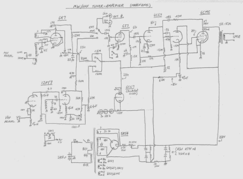
Circuit of the tuner/amplifer.
The AM tuner
Anyone who's seen
the rest of this site would have worked out that conventional superhets
aren't my thing, and so of course a regenerative detector was chosen for
the AM receiver. Again, wanting to use a G style octal valve, and knowing
it was a good circuit, I used the circuit from Radio & Hobbies, April
1943 called the "Tiny Tim".
This used a 6J7
with potentiometer controlled regeneration. I've never liked the more common
(in Australia & the UK) variable condenser control. Apart from needing
a bulky, expensive, and now not so obtainable component, the performance
is not very good. Backlash is awful and then there's the detuning effect
as the regeneration is adjusted.
Potentiometer control
has non of these disadvantages. With pentodes, the screen voltage is adjusted
to control the gain of the valve and therefore the point at which oscillation
almost occurs. For triodes, the plate voltage is adjusted instead. There
are various ways of creating the feedback path; usually a third winding
on the aerial coil is used. It can be in either the cathode, plate or screen
circuit, so long as some of the incoming RF flows through it out of phase.
For the Tiny Tim circuit, the screen grid is used as the anode for the
feedback winding. Operation is smooth and predictable.
For this project
I actually used a 6K7 as it was what was immediately to hand. I didn't
find any real difference between it and a 6J7. The difference between these
valves is that the 6J7 is sharp cut off and the 6K7 is remote cut off.
In theory, a sharp cut off valve is better for this application but the
6K7 works so it stays.
Because of strange
loading effects of my long wire aerial, I generally have to place a bit
of capacitance in series with the aerial primary in order to get the regeneration
to work across the band properly. Hence, the two aerial terminals.
Separate variable
condensers are used for the AM and FM sections, and wishing to use only
one dial I had to gang them together. This I did by means of dial drums
and cord. It worked out very well.
FM Tuner
This one's been
covered enough times not to say much further here. It is of course my favourite
12AT7
super regenerative receiver. However, I did use a 6201 valve in place
of a 12AT7; it's the industrial version. Initially, the receiver performed
poorly with more noise, poor sensitivity and a seemingly impossible to
get rid of quench beating problem. It wasn't the 6201 either; I did try
a 12AT7 with no improvement. It seemed the quench frequency was too low
all the time. Upon replacing the 330K grid resistor with 270K, the performance
came up to what I expected it should be. I can only assume that it was
a whole lot of component tolerances adding up in the wrong direction. The
regeneration control in this receiver is of the later method where no C-
supply is required.
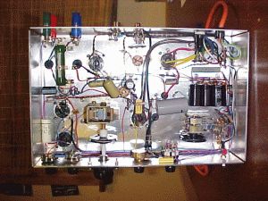
Underneath view. Note the two variable condensers ganged together.
Power Supply
A bit different
to the average receiver; this uses a power transformer from a Hewlett Packard
715A klystron power supply. With the 6CM5 drawing 1.2A for it's heater,
the typical 2A 6.3V winding found on most power transformers would be inadequate.
The HP transformer has more than sufficient capacity, spread over three
windings, for all the valves. The 5V rectifier heater winding is rated
at 3A, so I could use a 5AS4, which looks impressive from its size. One
of the reasons why such a valve would be used is that the secondary windings
are roughly 480V a side of the centre tap, even though the maximum current
available is about 50mA.
So, this extra voltage
caused a few problems. With the highest voltage required being about 270V
for the output stage, there were a lot of volts to get rid of. 55V is lost
across the back bias/ filter resistor. Keep in mind that the DC voltage
is the AC multiplied by 1.4142. The problem of dropping such a high voltage
at approximately 55mA is the heat from the resistors used. I initially
thought a light bulb would be the way to go. As it turned out, a 25W 240V
lamp with a 300 ohm 10W resistor in series did the trick, or instead of
using the resistor, a 40W lamp was used. Electrically it was a good solution,
but the glare from the 25W bulb was just unpleasant coming from the top
of the exposed chassis. So I had to go back to using resistors. a 2.2K
50W resistor was installed above chassis with an adjustable 1K 20W to set
the B+.
So up to this point
we have our required 270V B+ and -55V C-, but what about the warm up? With
about 670V on the filter condensers when the unit is first turned on (the
5AS4 is directly heated), it would mean condensers of at least this voltage
would have to be installed in all the filtering and decoupling positions.
Not convenient, with electros not conveniently available above 450V and
also the ceramic condensers used in the receiver sections being typically
400V. So a sort of pre regulator was devised using a 6CG7. Apart from the
output stage, all the tuner/amplifier's supplies are derived from this
source. Three series connected neon bulbs limit the voltage on the
grid to about 270V and the parallel connected triodes simply function as
a cathode follower. Thus the secondary B+ can never go above this voltage.
Thinking about this further, I realised the neon bulbs aren't really necessary.
By the time the 6CG7 has warmed up, the main B+ will be down to about 270V
anyway. Note that the 6CG7 cathodes are connected to the heaters powered
from their own isolated winding, this has to be done to prevent the heater
- cathode voltage rating being exceeded.
The one other thing
that may attract attention, is that looking at the selector switch, it
can be seen there's some relatively high value resistors across the B+
contacts. This was done to prevent cathode poisoning of the 12AT7 and 6K7
when either or both were not being used.
Running a valve
with the heater powered but no cathode current for extended periods of
time is not a good thing to do and results in the cathode being unable
to emit electrons.
The voltage fed
to the inactive valves is about 30V. Enough for some plate current, but
not enough so that particular receiver becomes active. Simply leaving both
receivers active and switching the audio only is not good practice as it
may be possible to hear program material via stray capacitance or switch
leakage.
Performance.
The first thing evident is the sound quality.
It was far better than expected. While a sine wave displayed on a CRO will
show any obvious distortion, you really have to hear the amplifier to appreciate
it. In this case, the triode sound was plainly obvious. And yes I really
do agree that triodes do sound better than pentodes. It is a very noticeable
difference.
The bass response was the other surprise,
but then using a proper single ended output transformer, with a lot more
iron than is typically used, does help. I won't hesitate to use this 6CM5
design in future projects.
For the receivers, the performance is
the usual for their designs. The 12AT7 FM receiver, after the change of
grid resistor, performs like all the other ones I've built. Sound quality
can be very good but in general it isn't something you'd make recordings
from.
The 6K7 regenerative detector performs
well, with no regeneration control backlash. It's performance is exactly
the same as the Tiny Tim that I built up in 1997. In my location most stations
receivable on a superhet can be received on a regenerative detector using
a long wire aerial.