This 1935 model car radio was bought at
a swap meet in the mid 2000's. At the time, I was not able to identify
it as a Detrola, as the only badge, "Motoradio" did not appear on the nostalgia-air
site. However, in recent times with another look, I noticed the top
cover badge had on it, "Made in USA by D.R. Co". Since having acquired
another
Detrola (model 297) only a few years ago, I recognised the D.R. as
Detrola Radio. Some time searching through diagrams on nostalgia-air brought
forth a circuit which matched. It was model 6R. This is the same as the
listed 6M, except the 6R has no tone control. Having identified the model,
another search through other car radio listings showed it to be a 1935
model. From the valve types and general style, I had already assumed it
to be around this age, but now I had a definite year.
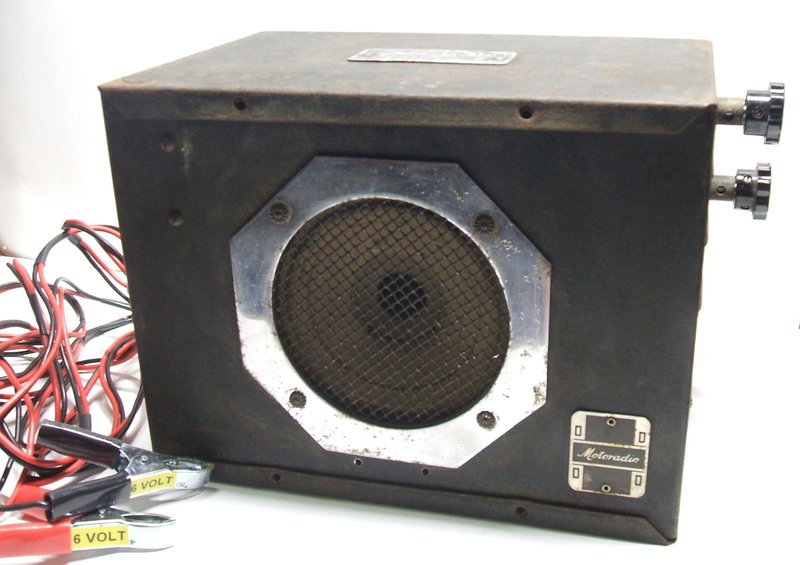
Like most car radios of this era, the
radio itself is a large box mounted on the firewall. The speaker is internal,
and the controls are remote, operated via Bowden cables from a small control
unit mounted on the steering column or dashboard. Being of U.S. manufacture,
it is of course for 6V operation.
See the Detrola operating here https://www.youtube.com/watch?v=6BNWYmkD6vc&feature=youtu.be
and here https://youtu.be/PQdPxCgbC5s
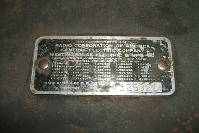
Patent plate attached to top of cabinet. Note at the bottom it says
"Made in U.S.A by D.R. Co.".
Rare in Australia.
Car radios of this age are extremely rare
in Australia. The conservative radio industry here did virtually nothing
to promote car radios, pre WW2, and in any case their high cost meant that
they were a luxury item. While it is true that car ownership in Australia
was also very low, of the cars that did exist (and a surprising number
have survived) hardly any were fitted with radios. Even post-war,
few radio manufacturers, with the notable exceptions of Astor, Ferris,
and AWA, had much enthusiasm for producing car radios. This state of affairs
lasted until the 1970's when Japanese imported cars were being sold with
radios included. This forced local car manufacturers to reluctantly include
heaters, radios, and clocks in their own models as standard accessories.
The result is that valve car radios are
relatively uncommon in Australia, especially pre-war models. This is quite
different to the U.S. where they became a standard fitment to post-war
cars.
How this 6R came to be in Australia is
unknown. One could assume that it came in a car imported from the U.S.,
although the import tariffs and the right hand drive requirement discouraged
this practice. Certainly, U.S. made radios were not sold on their own in
Australia because of import tariffs. Perhaps one of the more commonly imported
Canadian cars was the source of this radio?
Examination of the 6R.
Not surprisingly, the control head was
missing. One is doing well if a car radio appears with its Bowden cables
and control head. And, with single unit sets, you're doing well just to
get a dial. You've hit the jackpot if you get the escutcheon and
the knobs! My plan therefore, was just to use the radio as a kind of "picnic
portable", with control knobs on the set itself. The idea would be to sit
it on the running board of the Model T for listening, while stopped somewhere,
and to connect it to the battery by a lead and clips.
Inside the set, all the valves were present,
but the Goat shields were all missing except for one. The vibrator was
also missing. Otherwise, everything looked good.
I thought it was a nice well thought out
touch to have the valve type numbers actually stamped into the valve sockets.
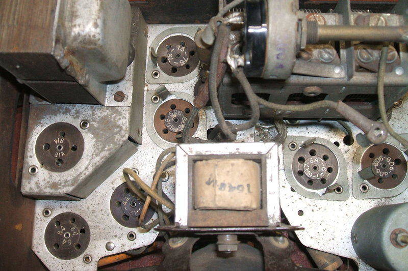
Type numbers stamped into the valve sockets makes things easy for
non technical types who wish to get all the valves tested, and of course
for future collectors!
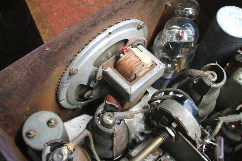
Under the chassis it looked as though there
had been no servicing since the 1940's.
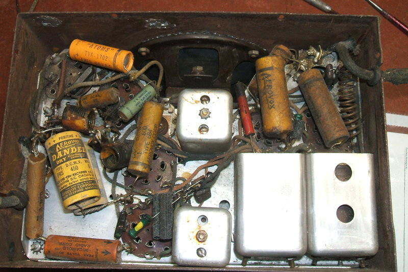
Despite the original appearance of these old condensers, the radio
had actually been recapped in the 1940's. Note the two holes in the coil
can at the right. These allow access to the tuning condenser mounting screws
- once the coil is removed from the can, which involves removing the entire
chassis from the case.
The 6R is a standard 6 valve superhet. There is a .01uF between the 100K and volume control which is not shown. Also missing is a .1uF B+ bypass.
There is nothing much unusual about the
circuit. The aerial coil feeds a 6D6 RF amplifier, which in turn feeds
the input of a 6A7 pentagrid converter. As the oscillator coil (also the
aerial and RF coil) is not adjustable, a variable padder condenser allows
correct tracking between the RF and oscillator circuits, to produce a 262
kc/s IF. This choice of IF might seem strange to the modern enthusiast,
but was quite common with portables and car radios. The advantage is higher
gain than would be provided with a 455 kc/s IF amplifier.
Selectivity is also improved, but the
image rejection is not as good. This is not important here where the RF
amplifier is tuned. It is for this reason that the 175 kc/s IF fell out
of favour. In strong signal areas, stations might appear at two points
of the dial with such sets, unless they had a TRF stage or preselector.
The IF amplifier is another 6D6 remote
cut off pentode. The IF transformers are air cored types adjusted by trimmer
condensers. Interestingly, the secondary of the second IF transformer is
untuned. One wonders if the loss of gain here is important. The secondary
feeds one diode of the 75 for demodulation, where the audio proceeds to
the volume control, and then the grid of the 75 triode. The other 75 diode
is shunt fed from the primary of the second IF transformer to provide the
AVC voltage.
The first three valves, 6D6, 6A7, 6D6,
all use a common bias resistor of 100 ohms. This saves having to have 300
ohm resistors, and associated bypass condensers for each valve.
Similarly, their screen grids are all
fed via a common 20K resistor from the B+.
The output valve is a 42 pentode used
in the normal way. The choice of bias resistor bypass condenser seems rather
low for the 42 and 75 valves. At only 5uF, the bypass for low frequency
audio signals will be poor, resulting in a sound with more treble than
would be normal. Perhaps this was intended for intelligibility in a moving
car, with road and engine noise competing with the radio.
The tone control is only part of the 6M,
and not the 6R. It's a simple variable top cut control.
The speaker is a 5" electrodyamic type,
with the field coil energised from the 6V supply. This is more efficient
than the conventional method of using the B+ current flow to energise it,
and makes things easier for the vibrator power supply.
By 1935, B+ batteries or genemotors were
obsolete for car radio use, so of course a vibrator power supply provides
the B+. It is interesting to note that this set was made only two years
after the full wave vibrator had become standard. The circuit here is completely
conventional, with a .0075uF buffer condenser to tune the transformer to
the vibrator, and a 100 ohm damping resistor across the primary. An 84
rectifier provides the B+ from the transformer. This valve was developed
for car sets (domestic sets remained using 5V directly heated valves such
as 80 for quite a few years), because for car radio service an indirectly
heated cathode is required. While one could run an 80 heater off
the vibrator transformer, efficiency would be considerably reduced, and
such an increase in load (an extra 10W) would be undesirable for the vibrator.
The 84 soon became known as the 6Z4 with the RMA numbering system. When
octal bases appeared, it then became the 6X5, and then the later 7 pin
miniature 6X4.
A simple resistive filter with two electrolytics
provides a reasonably clean B+ at 240V. The 1000 ohm filter resistor is
riveted to the chassis for heatsinking.
For the 6V input, the usual array of air
cored chokes and bypass condensers filters out vibrator interference, and
any incoming electrical system interference on the car supply.
Aerial, pilot light, and the 6V input connectors are of a bayonet type common to car radios. While they look remarkably like that of an MBC dial lamp base, the diameter is unfortunately not the same.
The first obvious problem was that the
tuning condenser and volume control shafts weren't lining up with the two
Bowden cable attachments on the side of the cabinet. The reason was the
rubber grommets, on which the tuning condenser is mounted, had hardened
up and partially decomposed. I'm not sure why so many manufacturers mount
their tuning condensers on rubber grommets when they are operated by a
dial cord. It's not as if they need to be electrically or mechanically
isolated from the chassis, but in this case, some mechanical give is desirable
because of the direct connection with the Bowden cables, to prevent binding
as the shaft is rotated.
The first hurdle was to replace these
three grommets. And here I saw the first, let's shall we say, less than
desirable aspect of servicing this set. Understandably, car radios are
of compact construction, but really, having to remove the aerial coil from
its can to get at the tuning condenser screws is pushing things too far.
Not only that, to get the coil out of the can, the chassis has to be removed
from the case, along with the speaker. Fortunately, removing a number of
screws allows the chassis to simply fall out of the case, giving the improved
access.
Having desoldered the aerial coil wires
and extracted it from the can, we now had access to the front condenser
mounting screws and grommets. I had just the right size for replacement
and proceeded to install them. Alas, the shafts still didn't line up. I
really wondered how they ever did...
Eventually, after much experimentation,
I found packing up one foot with a washer tilted the tuning condenser so
that mechanical alignment was acceptable.
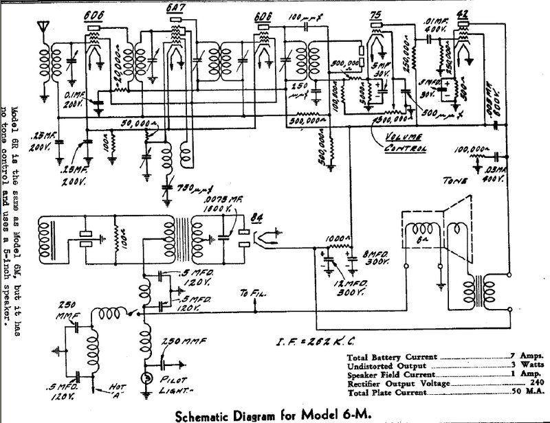
New Controls.
Next was to make up the new control shafts.
Fortunately, the Bowden cable receptacles were 1/4" diameter. This meant
I could cut down a piece of 1/4" rod to make the shafts, and they would
fit normal knobs with no further work. Making the new shafts was all straightforward,
but the ends had to be filed into a slot, so as to engage to the
existing controls. Sections of 1/4" fuel hose were pushed over the shafts
to retain them in place.
Once this was done and suitable knobs
were fitted it was time for the electrical restoration.
How to use a radio with no Bowden cables.
Strange things...
It quickly became apparent that this radio
had been recapped in the past, and by the appearance of the "new" types,
I would say mid to late 1940's. When we talk about recapping a radio in
the modern day, it's to replace all the paper condensers with polyester
types to forever eliminate the leakage problem inherent to paper types.
However, recapping 1940's style was with...paper types! Whoever had done
the job had simply cut off the old components at the valve sockets, and
soldered the new components on top of the old lead ends.
That always smacks of a lazy rush job
for profit rather than good workmanship. However, in this set it wasn't
very difficult to remove the lead ends...not like certain Australian manufactures
who loved winding leads as many times as they could through the tags before
there was no room, and then crimping them tight with pliers just to make
sure. But, in this case it did leave useful clues as to the radio's past.
As I worked through the resistors and capacitors, I found some rather odd things which made me question the knowledge of the serviceman. Not that the things done would prevent the radio working, they were just very weird, and one "repair" would have caused short vibrator life.
Normally, low value resistors are quite stable and almost never need replacing. Not the Micamold types used here though... The 100R cathode resistor for the front end valves measured 260R. The 42 cathode resistor, which should be 500 ohms was measuring 1000 ohms. While these changes in values would not stop the radio working, sensitivity and power output would be reduced.
The 75 plate resistor was 500K, and it appeared to be the original. This is at odds with the circuit (and conventional practice) of using 250K. While 500K can be used in some situations, this was definitely not one - the 42 grid resistor was 250K, not only in the set, but on the circuit diagram. While 250K seems low for an output valve grid resistor, it's actually good design for a car radio. This is because with the higher temperatures of car sets, caused not only by the ambient heat of parking a car in the sun, but also by the cathodes running at higher temperature than they do in domestic sets. This is because of the car electrical system being at least 7V instead of 6.3V, with the engine running at speed. High grid resistors like 500K or 1M increase the chances of grid emission, which will eventually ruin the valve, as well as overload the power supply.
The problem here was that 500K is unsuitable as the preceding plate load. For maximum power transfer, the following grid resistor must be equal to or higher than the preceding plate resistor. Obviously, the radio would have worked, but just not optimally. The 500K plate load had gone high anyway, so I replaced it with a new 220K.
There was a .01uF in series with the volume control input which was not shown on the circuit. It's actually correct to have this, so that the track of the volume pot does not have DC flowing through it. Thus, I replaced the condenser. Further, there would have been more DC loading of the detector with the circuit as drawn, which is not desirable for distortion.
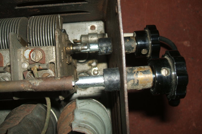
Condensers.
There was also a .1uF B+ bypass in the
set, not shown on the circuit. It was impossible to tell if there was originally
one before the recap, but as it's the correct thing to do, I replaced it.
Just the 2nd filter electrolytic cannot be relied on because it is ineffective
as a bypass at RF. Leaving out the .1uF B+ bypass is a favourite cost cutting
measure with many manufacturers, but it means the radio becomes unstable
as the electrolytics age.
There were two 1940's style Aerovox 8uF
450V electrolytics; obvious replacements, which I had just assumed to be
the first and second filters. Not so! To add to the bizarre situation,
the first filter turned out to be a 4uF 450V! As you can see from the circuit,
it was originally 12uF. The second filter was indeed one of the Aerovoxes,
but what was the second Aerovox for? What else but the 42 cathode bypass!
Yes, an expensive and large 450V capacitor with only about 13V ever across
it. Ironically, that 4uF used for the first filter was closer in value
to the original 5uF 42 cathode bypass, even though, again, the 450V rating
is ridiculously high.
Given my success with some American 1940's
electrolytics, I thought I'd see if the two Aerovoxes could be reformed.
Indeed, they responded well and they were retained, but in the correct
positions this time!
The 5uF 75 cathode bypass was not usable
- the negative lead had detached from the aluminium foil.
The vibrator sub-chassis. The two .5uF's and choke are visible for
the 6V supply. To the left is the Micamold 100R resistor across the vibrator
socket. Strangely, the buffer condenser I'd expected to see wasn't here.
Getting it out involved desoldering the
short 6V supply wire, and then the equally short rectifier socket wires
for the AC, and then finally a short length of earth braid. After that,
three nuts had to be removed, one inconveniently mounted under some leads
attached to a tagstrip sharing the same nut. It was just easier to do this
with the chassis out of the cabinet, so again the cabinet had to be lifted
off and the speaker removed.
Once removed, I was surprised to see no
buffer condenser; just the the two 6V filter condensers. Where else could
it be? A closer look at the rectifier socket solved that mystery.
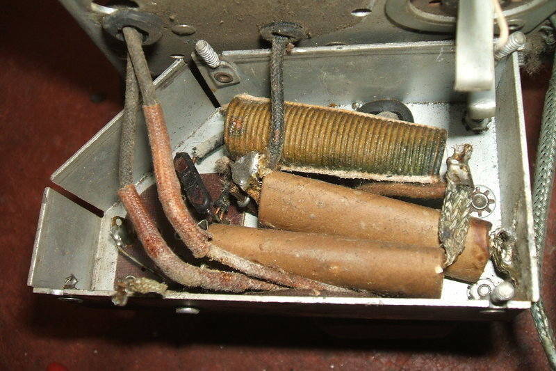
No Buffer.
Yes, some idiot had simply chopped out
the buffer - its lead ends were still wrapped around the socket pins. The
radio would have been going through vibrators at a rapid rate, leaving
the owner to think vibrators are unreliable. Here we have a classic example
of an abused vibrator power supply. Yes, the radio will work without, but
with high peak voltages across the contacts, especially before warm up,
and no tuning of the transformer, the contacts will wear rapidly. It's
also quite possible for the transformer and rectifier and rectifier socket
to be damaged by the high peak voltages due to this mistreatment.
While the subchassis was out, I checked
the 100R damping resistor. As it was also a Micamold, I wasn't surprised
to see it had risen to 200R, so it was replaced. As the .5uF's are across
the 6V supply, any leakage was not important, so they stayed. As can be
seen from the photo, their leads are braided wire to provide a low inductance
connection.
I noted that the vibrator socket was wired
for a shunt drive type. Pin 4 had also been earthed. This pin is normally
not connected with most shunt drive vibrators, but there are a very few
where pin 4 is the reed instead of the usual pin 1. Presumably this was
done to allow a greater choice of vibrator types.
So with a missing vibrator, what to replace
it with? Of course, I could have used any of the 6V four pin vibrators
in my collection, but in my catalogs, the Detrola 6R was listed, along
with the Radiart and Mallory types recommended. It just so happened I had
the Mallory type, a 294, so that's what went in. The catalogs also confirmed
the buffer being .0075uF.
A brief check of the 294 contacts confirmed
all was good, which I pretty much expected from a Mallory that hadn't been
abused in its previous life.
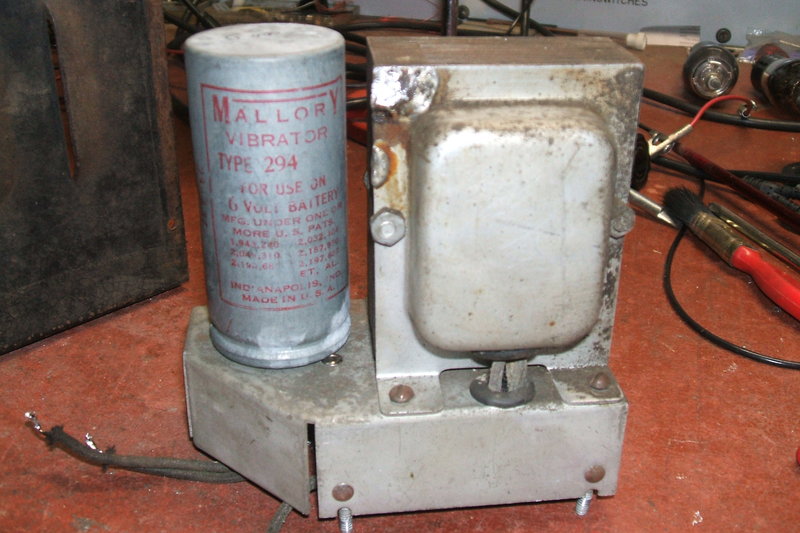
Mallory 294 installed and ready to go.
What to use for the buffer? .0075uF is not a preferred value, so I had nothing modern. I could have used two .015uF's in series, but it just so happened I had some .0082uF 1600V types. These were intended for tuning colour TV line output stages, so are perfect for this kind of application. As I've pointed out elsewhere, while the buffer value is very important, it is not generally problematic going up slightly in value. I did try both values to confirm (most important!), and the difference between .0075uF and .0082uF was indiscernible on the CRO waveform. Certainly, vibrator power supplies must always be checked with a CRO when restoring them. Differences between vibrators can mean a buffer ideal for one is unsuitable for another, among other things.
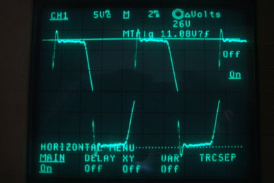
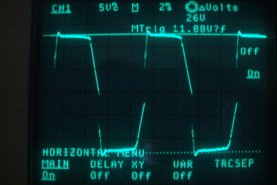
No load vibrator waveforms, at left with only the .0082uF buffer,
and at right with a 5.6K series damping resistor.
I noticed there was some overshoot, and this was almost eliminated with a 5.6K damping resistor in series with the buffer. If I was to be pedantic, I would have included the 5.6K but as it was not convenient to mount, and the overshoot did not seem problematic, I did not include it.
At this point with the 294 happily buzzing away and producing the correct waveform it was time to reassemble everything.

Fully recapped. Note the yellow condenser in the top left corner
- note that there was nothing there in the previous unrestored photo -
it's the buffer.
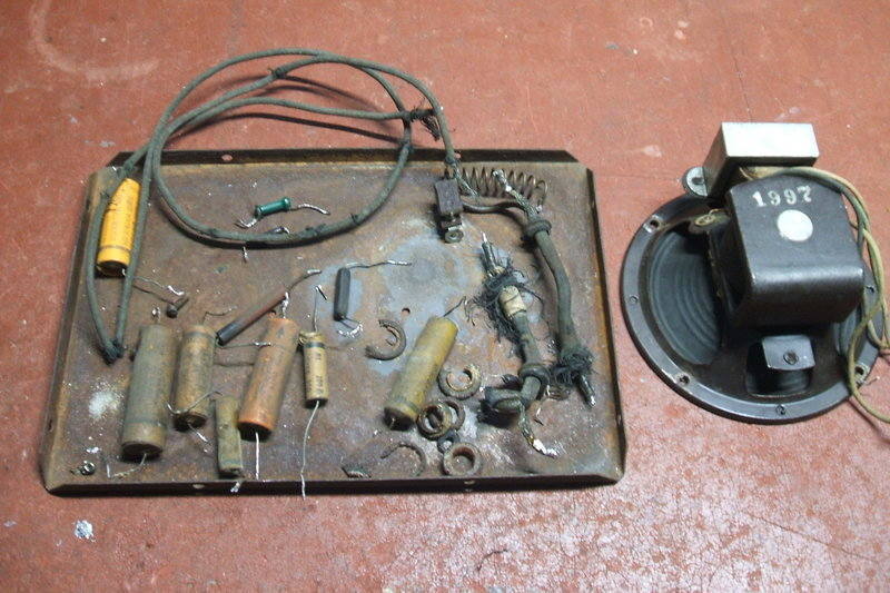
The final collection of replaced components.
Now, there were signs of life, although
rather lacking. The gain was terrible, with only the strong 50kW ABC 2BL
and 2FC transmitters receivable. The rest of Sydney's MW stations
were so weak and masked by noise to be of no entertainment value at all.
This was obviously not right, not only for a car radio, but one with an
RF stage.
Aside from that, was the absolutely awful
distortion from the speaker. I can't recall anything so hideously sounding.
Noting that most of the Goat shields were missing from the valves, I replaced them, and then tested the alignment. The IF channel did need a slight tweak to bring it all up to 262 kc/s, and likewise the front end, but it wasn't much better. In fact, the distortion from the speaker put me off working on it. How could I describe it? As I'd approach the set on my bench I'd think twice about switching it on - for I knew what I'd hear when it warmed up. And, that was not nice!
Vibrator stops.
A peculiar thing became evident around
this time, in that the vibrator would stop when I tilted the set a certain
way, and the 6V current went up. It wasn't the vibrator, because connected
with flexible wires to my current limited power supply, I could hold it
in any position and it kept running.
This meant only one thing...out with the
vibrator sub chassis - yet again, and all the work that entails. And there
was the problem - or so I thought. A loose screw left in the set used to
hold down the original filter electrolytics. It was jammed in between one
of the 6V tags on the tagstrip so it was also touching the chassis. I reinstalled
the subchassis and tried again.
Well, yes it seemed ok, but then it happened
again. This time the current dropped.
Again, the vibrator ran fine externally
to the set. So, for the 3rd time, the subchassis came out. I found
pushing the vibrator in its socket one way would cause the fault. Something
to do with the socket then? It turned out that the earth connection had
broken where it was soldered to the chassis. There wasn't much flexibility
in the tinned copper wire, and the reality is the socket flexes when the
vibrator is removed or inserted. Once the wire was replaced there was no
further trouble.
IF Oscillation.
In the meantime, an oscillation had developed.
By removing the 6D6 RF amplifier and 6A7, I found it to be the IF amplifier
oscillating. This led me to find the 6D6 IF valve's Goat shield was not
earthed properly. The two spring contacts coming up from the chassis are
not particularly effective.
Speaker.
The speaker is not designed to be taken
apart, like many of its age were. The distortion seemed to be a problem
of voice coil misalignment, because by pressing on the cone in certain
directions, the sound would improve. There appeared to be limited adjustment
in voice coil centering by means of cardboard strips clamped under screws
at opposite sides of the speaker frame. Alas, the adjustment available
here made no improvement.
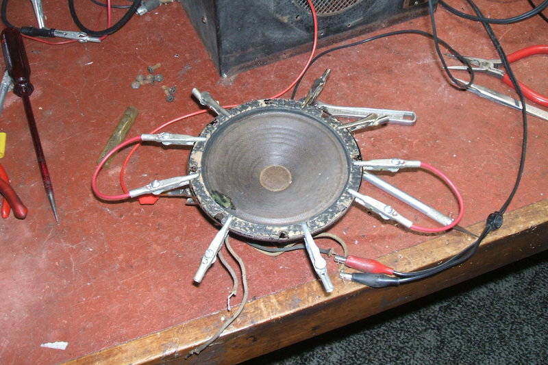
I took the speaker out, powered the field
coil from 6V, and connected a tape recorder to it for an audio source,
hoping that maybe just the frame needed to be bent into a certain position
to realign the voice coil. It seemed better, so put it back in the radio.
Annoying crackle.
Not a lot better at all. I also noticed
an annoying vibration sensitive crackle whenever the chassis was touched.
The 6V current draw fluctuated slightly in time with the crackle.
Eventually, I narrowed it down to the
42 socket. Even after tightening the socket pins and cleaning the 42 pins
with CRC. the crackle was still there.
Finally, I resoldered the pins on the
42 itself, and that was fixed.
The speaker - again!
Either the speaker had to be repaired,
or I would have to replace it. I'd rather not replace it because it would
mean using a more modern permanent magnet type which would look out of
place, and reduce the radio's character. After all, it's not like every
radio has a 6V electrodynamic speaker.
With nothing to lose, I removed the cone
and then the dust cover around the voice coil. It actually came apart easily
as the old glue was quite brittle. And here I found the cause of the problem,
which no amount of voice coil centering adjustment would have ever fixed.
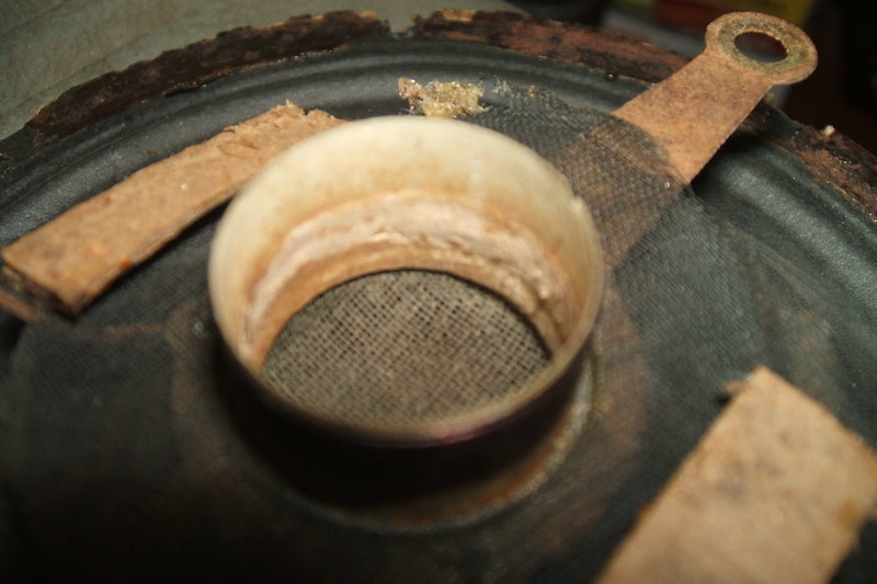
Swollen voice coil former was the cause of the hideous distortion.
Here, I've already scraped most of it away.
Something had caused the voice coil former to have swollen and increase in thickness. No wonder it was rubbing on the magnet. I scraped the extra thickness off and it seemed to fit better back in the magnet assembly.
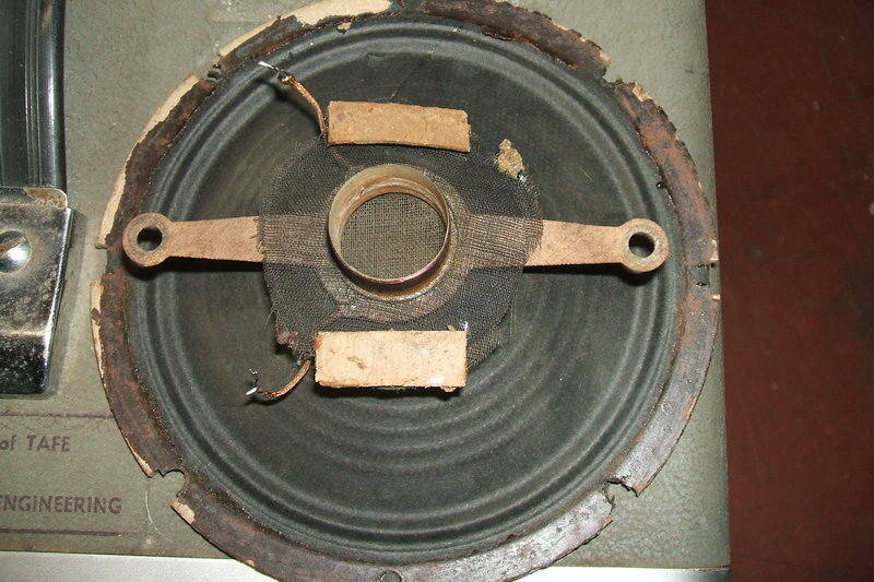
The method of voice coil centering is evident here.
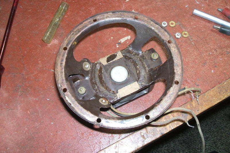
Speaker frame without the cone.
Waiting for the cement to dry.
I used Permatex No.4 gasket cement to glue it all back together. A small rattly sounding tear in the cone was repaired with contact cement. Connected again to the tape recorder, it actually didn't sound too bad once the voice coil was centered. In fact, it was what an old electrodynamic speaker usually sounds like.
Replacement Speaker.
Alas, after about an hour of listening
the problem was back. With the heat of the field coil (6W), and the heat
from inside the set itself, the speaker frame warped enough to cause the
voice coil to get out of alignment again. Evidently, I hadn't cleaned up
the voice coil former enough. At this point I gave up, and installed a
locally made permag Rola. It looked sufficiently old enough with its Bramco
output transformer. In fact, it worked out very well - Australian made
components being ten years behind the U.S., means that the 1940's speaker
looks just right in a U.S. made 1930's set. Importantly, I now had a radio
I could listen to.
Replacement 5" Rola with Bramco output transformer.
Front end alignment.
Having dealt with the awful distortion,
the front end problem could be dealt with. The radio lacked gain to the
point where it was actually no better than a crystal set. On top of that
was the worst interference I can recall from any set that I've worked on.
The only thing to do in this situation
is to start with the IF alignment again, then the RF and local oscillator
alignment, and also the padder condenser adjustment.
However, the IF adjustment was minor and
did nothing to improve sensitivity.
At this time, I discovered the screen
voltage for the front end valves was only about 50V. I had noted the screen
resistor (20K) was a bit high when recapping the set, but didn't think
it too important. But, with the gain so poor it was time to look at it
again. From memory, the screen grids should be closer to 100V, and I confirmed
this by looking up the valve data.
I changed the resistor, but instead of
using 22K as the preferred value, I used 18K instead to get a bit more
gain. Now the voltage was up to around 75 and the improvement was noticeable.
In the mid 1930's, the types of car radio
aerial in use were of various types. The modern telescopic aerial wasn't
standard until post war - popularised by aerials used on military vehicles.
With no information on what kind of aerial
the Detrola was meant to be used with, it meant I had nothing to go on
in terms of how to align the aerial coil, or if it would even peak up with
the aerial I wanted to use - a modern telescopic type.
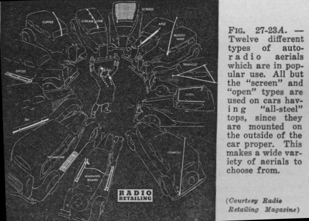
Types of aerial in use in 1935. What did the Detrola use?
All I could do was try it. As it turned out, the RF and local oscillator alignment was way out; more so than what I had assumed with my first rough alignment. The set wasn't able to tune much past about 1300kc/s. Like other sets this age, the only adjustment is the trimmer condensers, which really only affect the high frequency end of the band. One has to rely on the coils being matched during manufacture, in order that the low end alignment is satisfactory. Once I was happy with the band coverage, which I set for 550 to 1600kc/s, then the padder was adjusted in the middle of the band to get the best compromise with local oscillator tracking.
With that done, the gain was much higher,
and stations could be received just by placing my hand near the grid leads
of the RF and converter valves.
However, all along, since I first powered
up the radio, there was an awful interference present from about 800kc/s
to 1500kc/s. This was not making sense, because with no aerial plugged
in, the radio was silent, except for the usual white noise generated by
any high gain circuit. This ruled out anything inside the radio being the
cause, or anything coming through the 6V supply. It just had to be something
outside.
With a tuned loop aerial, freedom from
interference was considerably better. This indicated the interference must
be more electrostatic than electromagnetic. But why did other radios in
the same room not suffer like this? That is still not understood, and I'm
putting it down to some characteristic of the aerial coil being perhaps
self resonant at a particular frequency, or some other thing like a particular
input impedance.
Just because this all seemed so illogical,
I decided I'd run the set off a battery, away from the house and anything
electrical that could cause interference. I took the set out to the garage
and connected it to the Model T battery. The difference was amazing! It
was really like night and day. The Detrola was as quiet as you could wish
for, and not only all Sydney stations receivable clearly, but so was 2LT.
This station has directional characteristics which result in a very weak
signal to the east - where I am. It's always a good way to test sensitivity
during daylight hours.
The problem wasn't really a problem after
all, and the Detrola now works as it should.