These are being presented to help those who need a simple valve amplifier to go with a receiver or some other apparatus, or just as a low cost way to try a valve amplifier for those new to the technology. All designs here are in use in various television and radio receivers that I have built, so I thought I'd bring them together as not all the receivers have been presented elsewhere in the site. All have 'line level' type sensitivity which suits most applications.
Some notes: Volume
control resistances are not shown as these depend on the driving
circuit. 500K is typical for valve circuits; 10K-50K for solid state. Likewise,
the coupling condenser which has a non critical value; typically .01uF
to .047uF when a 500K volume control is used, or 1 to 10uF with the lower
values under 50K.
As class A single ended amplifiers are
about 40% efficient, a rough calculation to determine power output can
be made. P(approx) = .4(IxV) where P is the output in Watts, I is the plate
current in Amps, and V is the voltage from plate to cathode.
Not always shown, but one side of the
speaker transformer secondary should be earthed for stability. It is also
assumed that the B+ supply has been filtered and has sufficient capacitance
on the final filter condenser.
It is assumed the constructor is capable
of working out voltage ratings of condensers and wattage ratings of resistors.
Generally, cathode bypasses are 25V electrolytics, while others are polyester
400 or 630V types. Resistors are mostly half watt.
In most of the circuits 100V P.A line
transformers have been used as they are cheap and readily available. Some
more astute readers my notice that the impedance matching is not optimum
in some circuits; however this did not detract from sound quality. Please
see here for more
information on using 100V line transformers in valve circuits.
As for speakers; let's get rid of this
myth that low power amplifiers can only drive a "small speaker". In fact
nothing could be further from the truth. How often do you see a project
description where it used a low power output stage and the designer claims
it can "drive a small speaker". No! Use the largest speaker you can find.
Why? Simply because a large speaker has much more cone area. Thus, for
a given voice coil movement, more air is moved about. Not convinced? Try
it. The other thing so many project designers do wrong is fail to mention
that the speaker needs to be put in a box or baffled. This will increase
volume substantially, as well as improving bass response considerably.
A bare 2" speaker hanging off some wires attached to a PCB is such a sad
sight.
For those who want something with a bit
more power, see this 6BM8
article.
This circuit comes from my 5"TV receiver
built around a 5BP1 picture tube. The speaker transformer used was actually
a Jaycar M1112 with the 660mW tapping selected.
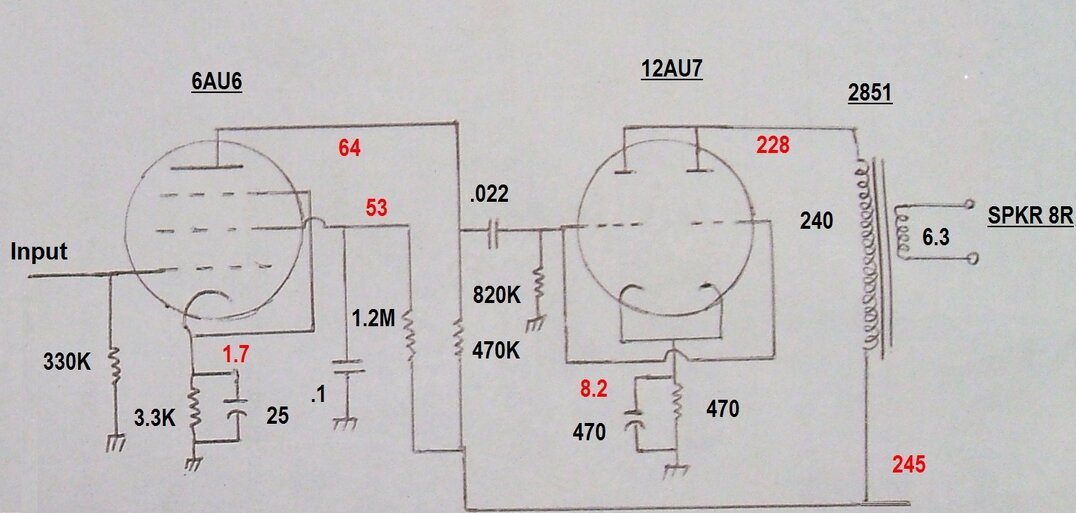
Current consumption is about 10mA. The
12AT7/ECC81 requires either 6.3V@300mA or 12.6V@150mA for the heaters.
Do not use other twin triodes such as 12AU7 or 12AX7.
These are not plug in equivalents as some
self appointed valve amplifier experts would have you believe. This amplifier
has good sensitivity and surprising power output for a triode, and a small
one at that. It is fed from the ratio detector in the TV set.
This circuit comes from the mains
operated TDA7000 receiver. The speaker transformer is the ubiquitous
2851 power transformer. This is rated at 240V to 12.6V CT @ 150mA, and
was used to obtain the necessary isolation from the mains supply. A conventional
speaker transformer can be used where the power supply is isolated, in
which case the optimum load is around 13K.
B+ is 245V at about 18mA. The input must
be capacitively isolated where there is any possibility of DC being present.
The 6AU6 grid resistor can be up to 1M if desired. Of course, this can
be substituted with a conventional volume control as shown in the other
circuits.
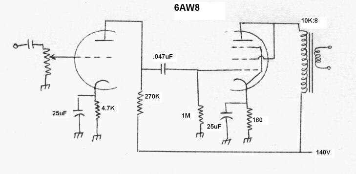
This one is from my home made Fremodyne receiver. Again, a 100V P.A line transformer is used with the 10K primary tapping selected. The 6AW8 pentode is intended for video output use and does not have audio data published. Nevertheless, a 20mA current rating makes it inviting for such use. Triode connection was chosen for stability. It also removes the need for a negative feedback network. The speaker used with this particular amplifier is an 8" dual cone. Heater current for the 6AW8 is 600mA@ 6.3V.
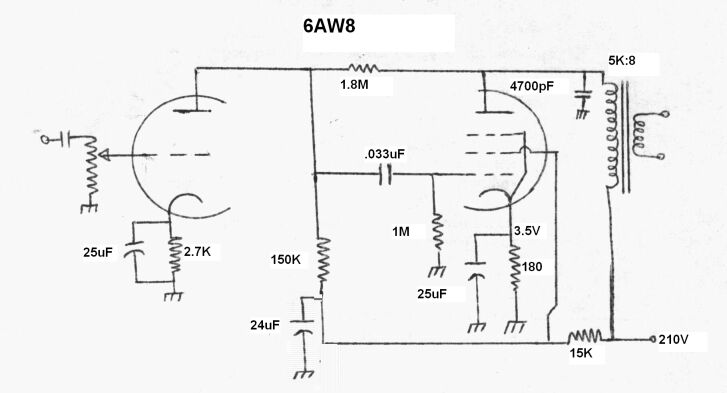
From my AM Stereo Receiver comes another
variant of 6AW8 circuit. This one is connected in a conventional
pentode circuit. Negative feedback is provided by the 1.8M resistor.
The now obsolete DSE M1100 line transformers
were used. For stereo, the 15K and 24uF can be common to both channels.
If this is done, parallel another 15K across the existing one. This circuit
was fed from the Motorola CQUAM decoder IC. The rest of the receiver is
standard with 6AN7, 6N8 and 6X4 valves.
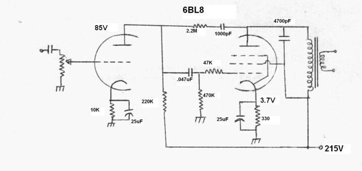
Used in one of my Pulse
Counting FM Receivers, this design puts out about 300mW. It requires
about 14mA at 215V for the B+ and 450mA at 6.3V for the heater. The 6BL8
is undoubtedly the most widely used TV valve in Australia. Europeans know
it as the ECF80, or its series heater equivalent, the PCF80 or 9A8. It
was originally designed for mixer/oscillator service in VHF TV tuners but
ended up being used in just about every section of TV sets except for audio
(well, there was the Thorn 980 chassis in the U.K that used it for audio
output), and deflection output stages. There are other similar looking
valves with the same pin connections; 6U8/ECF82, 6GH8, 6CQ8, 6EA8, etc.,
but they are not of the same characteristics. However, they would probably
work without any modification. There is also another valve, the 6JW8/ECF802
which is a non microphonic version of the 6BL8 meant for line oscillator
use. This should also work.
Output transformer in the FM receiver
is a 240 to 6.3V 300mA power transformer. This was used for mains isolation
as the receiver has a live chassis. A conventional speaker transformer
of around 15K primary impedance can be used, but the 1000pF in the feedback
network may need to be altered for correct frequency response.
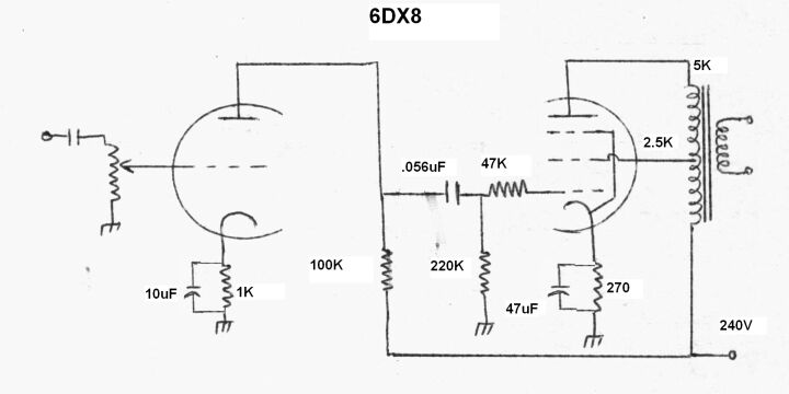
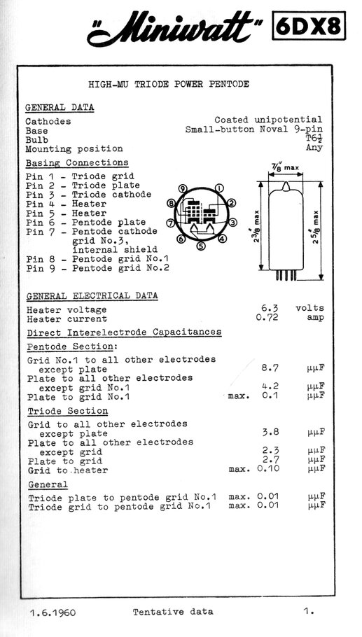
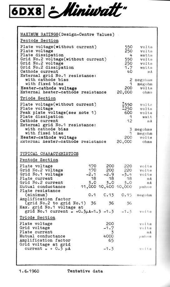
The 6DX8/ECL84 is another valve with the
pentode intended for video output service, and the triode for general use
such as AGC or sync separation. It is also a very common valve in Australian
TV sets. Unlike the 6AW8, this valve was given by its Australian manufacturer
Philips Miniwatt, ratings for audio output. Europeans would know this valve
better in its series heater form, PCL84 or 15DQ8 (15V at 300mA for the
heater). There is also a less common 450mA series heater version, 10DX8/LCL84.
The voltage across the 270R cathode resistor
is 3.8V, making the B+ current about 15mA. Heater requirements are 6.3V
at 720mA. I've used an ultra linear configuration in the output stage.
This effectively converts the pentode to triode operation while retaining
the benefits of the pentode. It's otherwise known as "Partial Triode" operation.
This results in improved sound quality over a conventional pentode connection.
An M1100 line transformer was used. As this is no longer available, the
Jaycar MM1900 can be used.
A conventional untapped output transformer
can be used by connecting the screen grid to B+. If this is done, a negative
feedback circuit should be added. It may also be necessary to bypass the
pentode plate in this situation. A typical value would be .0047uF 630V.
This amplifier is used in my Mains
Operated 12AT7 Receiver.
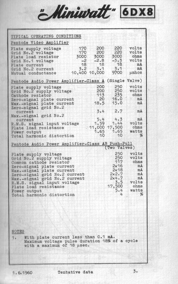
Philips in Australia provided data for single ended and push-pull
audio output use.
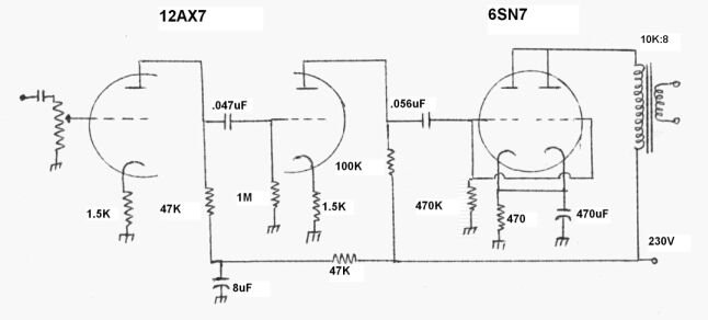
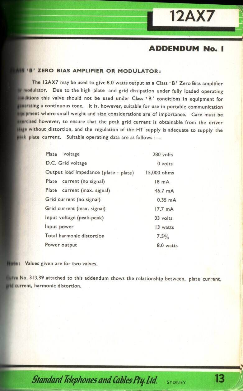
This one is another from one of my Pulse
Counting FM Receivers. Despite only putting out about 500mW, with a
decent speaker it is one of my favourites. All triode means no negative
feedback is required, although because of the high gain both 12AX7 triodes
have their cathodes left unbypassed. The output transformer is a Jaycar
M1109 with the 1W tapping used. The 12AX7 takes 6.3V@300mA or 12.6V@150mA
for its heaters, while the 6SN7 requires 6.3V@600mA. B+ current is around
20mA.
The 6SN7 has a modern nine pin equivalent,
the 6CG7 or 6FQ7. Another similar valve that should work is the slightly
higher power 12BH7. It requires 6.3V@600mA, or 12.6V@300mA. 12AU7 should
also work; it requires 6.3V@300mA or 12.6V@150mA for heaters.
6J7 and 6B8 as Audio Output Valves.
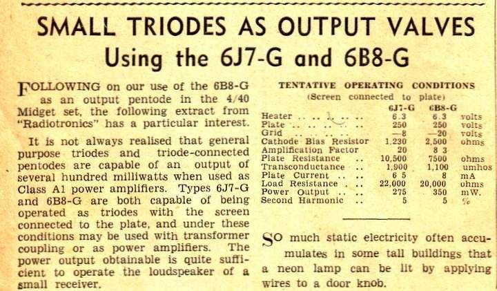
This article is from Radio & Hobbies, Xmas issue 1940. Previously, R&H had used a 6B8 as a conventional pentode for the output stage of their "4-40" receiver from December 1940.
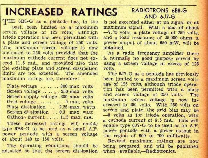
Revised data for the 6J7 and 6B8 as pentode output valves from May 1941 R&H
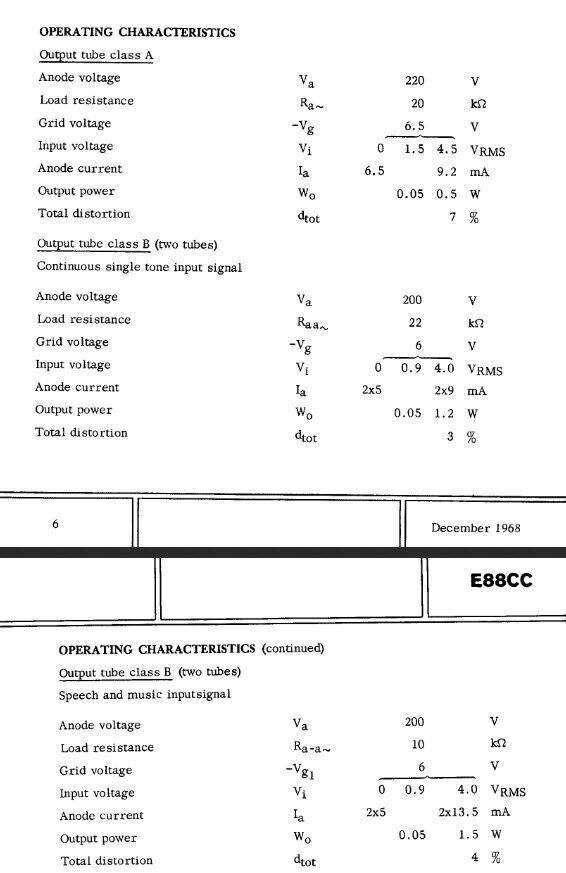
Since the characteristics are similar to the more common 6ES8/ECC189 it is interesting to speculate whether this valve can be similarly used.
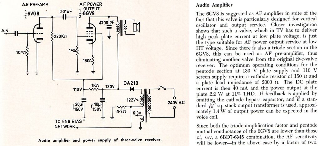
Note that the operating conditions here
are very similar to output valves often used in U.S. designed sets for
AC/DC operation. For Australian constructors, the 6GV8 is an easier valve
to obtain when wanting to duplicate such circuits,
provided of course the heater supply is
taken into account. This is 900mA at 6.3V.
The following is from the service notes
of the Pye T23 television receiver, released in 1965:
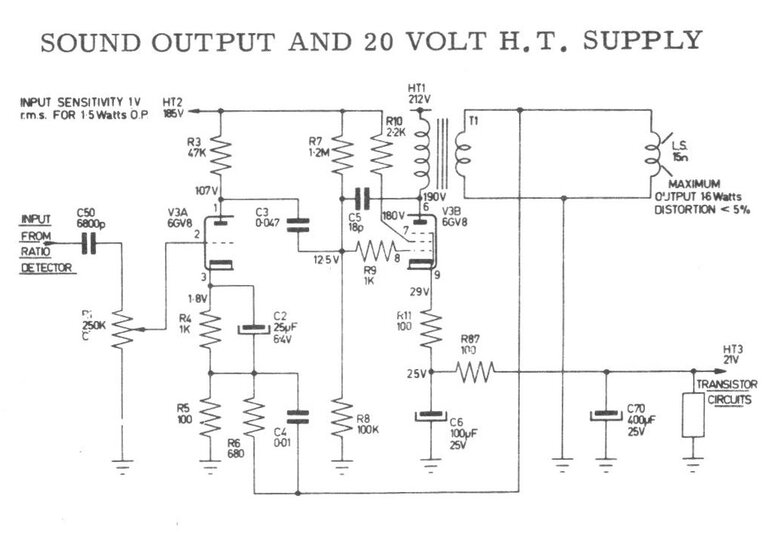
As can be seen, the 6GV8 pentode cathode
current also provides the low voltage supply for the transistor circuitry.
If this circuit was to be built without that feature, several modifications
would be in order. R7 would be deleted and R87 returned to earth. R87 would
also have to be changed to 330R. HT1 would be dropped to 200V. Load impedance
calculates to around 5k. Note that these are theoretical calculations and
have not actually been tested.
The Kriesler 11-99 was a four valve portable mantel radio, although later versions were fitted with a silicon rectifier, eliminating one valve. The cost cutting design suited the 6GV8 as the audio stage:
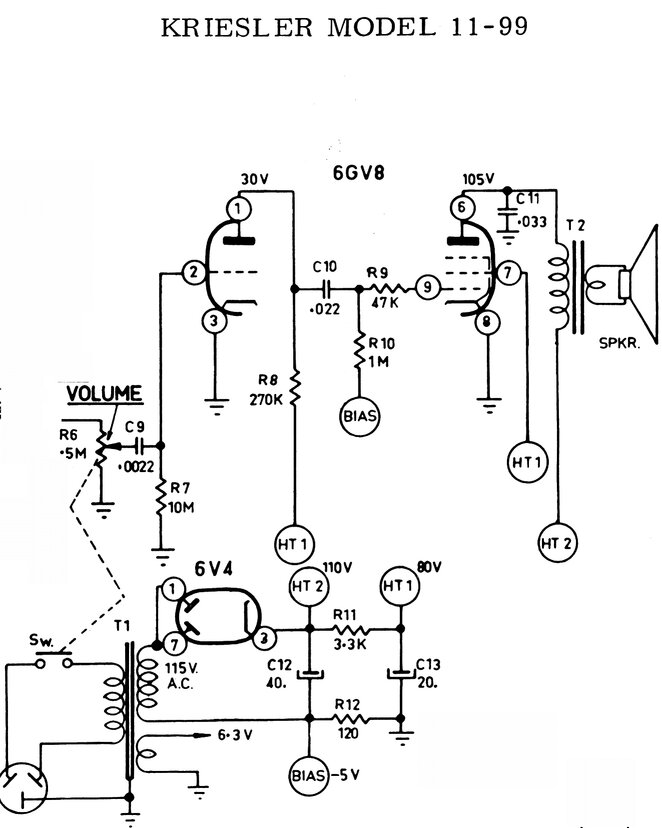
The speaker transformer is 3.3k to 15R. The output power is not specified in the service notes.
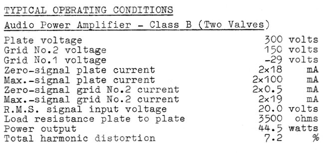
The 6CM5 is more suited to push-pull operation,
and Philips not only provided data for this, but produced several PA amplifiers
with 6CM5's used for the output valves.
Practical Television for April 1968 described
this "Teleamp" using a PL81.
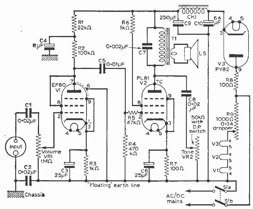
Circuit of the Teleamp. Practical Television for April 1968, along
with other issues, can be seen at the world
radio history site.
The operating conditions are questionable, and the circuit is presented here as a curiosity only. I have not built or tested it. Aside from that, the recommended output transformer was a 240 to 6.3V CRT heater transformer, and there is no negative feedback. Not exactly hi-fi!
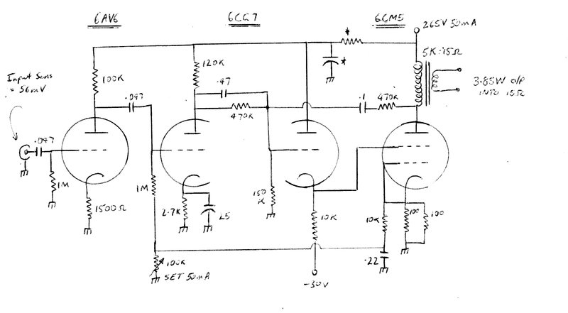
The following push-pull amplifier was designed
by Mullard, and would be a better design. The "Class B" designation is
questionable however, since there is no low impedance drive to provide
grid current to the PL81's. The method of obtaining bias for the output
valves is unusual to say the least. Surely it would have been easier to
half wave rectify the incoming AC, to provide the required negative voltage.
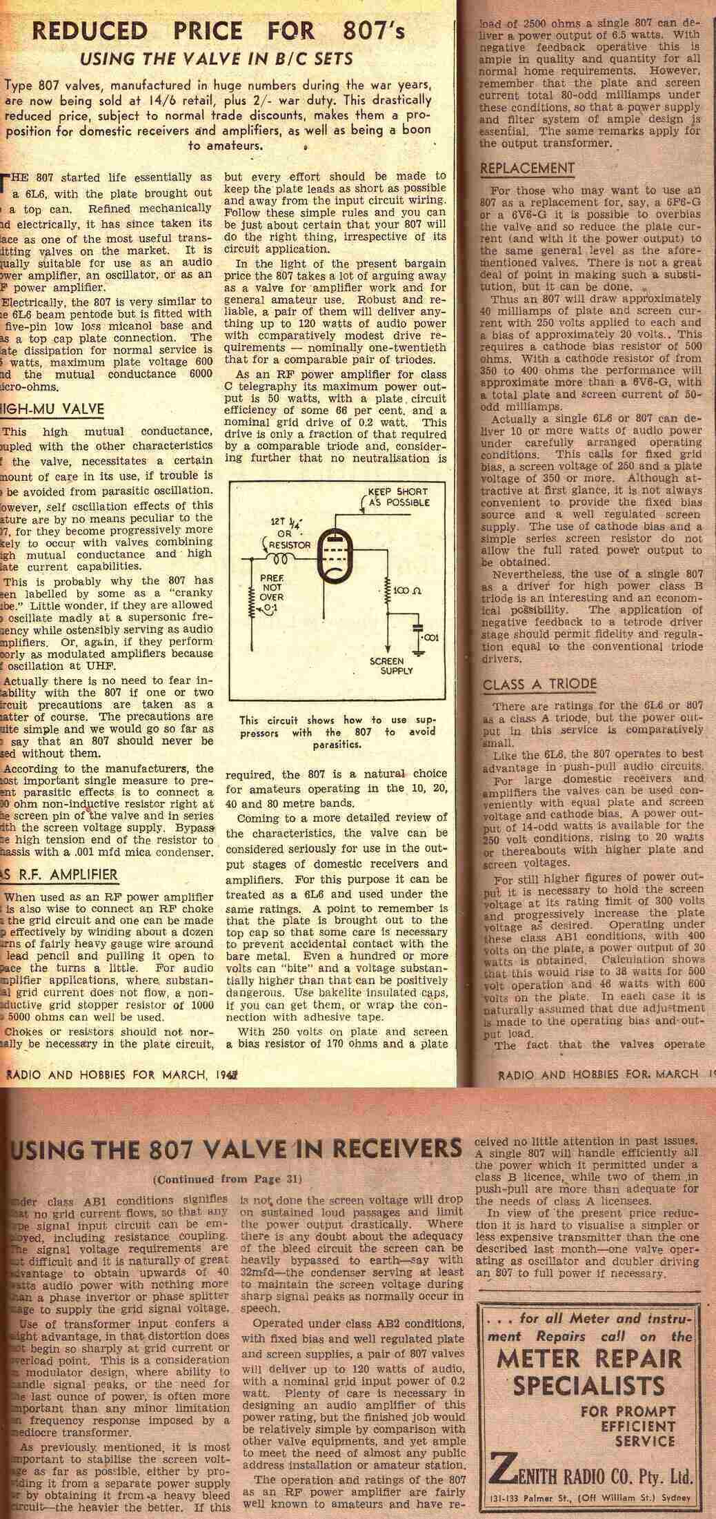
From RTV&H March 1947, the following
describes using the 807, which had recently been released inexpensively
on the disposals market. Of interest is substituting an 807 or 6L6 for
a single ended 6V6 (and 6AQ5 or 6BW6) circuits, by replacing the 250R cathode
resistor with 350-400R (390R in preferred values). The 6F6 (or 2A5 or 42)
can be substituted by using a 500R cathode resistor.
Note the increase in heater current if
doing this; 900mA for the 807 and 6L6, compared to 450mA for the 6V6.
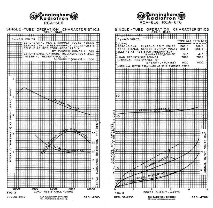
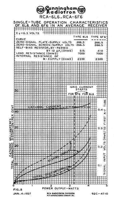
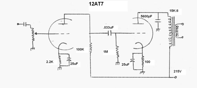
The following Application Notes from RCA
describe substituting a 6L6 for 6F6. Contrary to RTV&H's opinion in
the notes above, that the substitution is pointless, RCA claim that higher
output and lower distortion is possible when replacing the 6F6 with 6L6
(or 807), although the supply voltage and current, and load impedance remain
the same. The only thing is to ensure the extra 450mA heater current is
acceptable, and of course a UX 5 socket and top cap connection is provided
for the 807.