 Click
here to see full size.
Click
here to see full size.
Here follows an article I wrote for Paul Cambie (http://home.alphalink.com.au/~cambie/EL36.htm#John_Hunter). It was in reference to using the 6CM5 (or EL36 if you prefer using European type numbers) for audio amplifier output stages in single ended mode. The 6CM5 is a television line output pentode, and as such is meant for class C operation. While there is data for it as a push pull class B amplifier, no data has been published for single ended use. This isn't surprising as trying to use what is really a switching type valve in linear mode can't be very efficient. Class B push pull largely cancels out these linearities, but single ended is a lot more difficult. Here is the article:
Outside Australia the 6CM5 valve is virtually unknown. US, UK and European
data books often
do not show it. However, the series heater version, PL36, is as common
in Europe/UK as the
6CM5 is here. As a point of interest, one of my colleagues did the
curves for the 6CM5 at AWA
when they started making the valve. The Telefunken PL36 (the RMA number
for PL36 is 25E5),
is what the local AWV production was technically compared with, that
company being the
European AWA affiliate).
It is important to remember that series heater TV sets were standard
in the UK and Europe,
whereas parallel heater designs were pretty much unique to Australia
and about half of US sets.
(New Zealand followed the series heater designs to a much greater degree
than here in
Australia). The very few parallel heater TV designs in the UK used
the 6CD6 or 6DQ6. (I'm
talking 1950's~1960's here). In the US, the standard line output valve
of the era was the 6BQ6 or
it's higher rated version, the 6DQ6. The 6CM5 is not a plug in equivalent,
although it does have
the same pin connections.
What is unique about the 6CM5 is the low anode voltage. Again, the series
heater TV design was
responsible for this. When the B+ comes only from the 220Vac European
power mains, the
filtered DC supply is only about 200Vdc, (and maybe even lower for
DC mains supply), for the
whole TV set. So, any line output valve is going to need a very small
voltage drop from anode to
cathode when it is turned hard on. When you've got 250Vdc of B+ from
a transformer supply or a
voltage doubler running off 120Vac, inefficient valves like the 6DQ6
are okay.
This means that for Class A audio, the 6CM5 is one of the worst valves you could use. Class C is what it is most efficient for, and also Class B (I have one of the Philips public-address amplifiers with 6CM5's operating in pretend Class B).
Not to be deterred, I have experimented just to see what I could get out of a single-ended Class A output stage. (Actually I've got a car radio project coming up . . .)
I tried three methods of using the 6CM5: 1) conventional pentode with drive to the control grid, 2) pentode with drive to the screen grid, and 3) triode. The conventional pentode connection was the worst! I couldn't really get good linearity with decent output power. Screen grid drive was a lot better, even though about 42Vp-p was required to drive it.
The best was triode connected. Although sensitivity was low, again requiring
42Vp-p, the output
was the greatest and distortion the lowest. Maximum output was about
2.25W into 5kOhms with
a B+ of about 260Vdc at 50mA. These tests were done with a regulated
valve power supply, (a
BWD model 215). The results aren't really surprising, and after looking
at the STC manufacturer
data on the 6CD6 when used as a single-ended Class A output stage,
it just confirms what I
suspected. (For triode connection the output is 1.5W and for pentode
it's 4.7W - as a point of
interest, they also mention that 6CD6's used for audio are liable to
have a large spread in their
characteristics and they're basically not recommended, except as a
point of interest for low
anode voltage supply).
So, yes it can be done, but it's terribly inefficient when you consider
that the heater current is
1.2A (6.3V @ 1.2A = 7.5W heater power alone, for 2.25W useful audio
output!). A 6AQ5 or
6V6 will give nearly double the output power for less than half the
heater current! I have seen a
$3000 amplifier made in Western Australia using a colour TV line output
valve
(PL509/40KG6). It only gave out 7W! (Sorry I refuse to believe valves
such as this are capable of "sonic transparency" and other nonsensical
descriptions though up by the emotionally driven golden ear brigade...anyone
who pays lots of money for an amplifier made out of television line output
valves is being ripped off. You wouldn't buy an amp with a Triac or SCR
as the output device would you? And don't get me started on oxygen free
cables...!)
I intend to go ahead and use the 6CM5 in single-ended Class A applications
but only where
heater current isn't a problem and a couple of Watts is acceptable
output. But there are better
valves for the job, and it's only because of my quantity of 6CM5's,
(and wanting to be different),
that I'll use it. Having said all that, the low anode voltage is of
interest, as it may permit a valve
amplifier to operate on low voltage power supplies. This I have yet
to play around with.
I guess I should emphasise that my disappointment with this valve was
with its application in
single-ended mode. For push-pull audio, transmitter output stages,
and as a B+ regulator series
pass valve, I think it has a lot of potential.
John Hunter, 26 August, 2002
I have, with much perseverance, got the 6CM5 to work as a single ended
Class A audio
amplifier. The operating conditions are most bizarre (no bias, and
25V for the screen grid), but it
really does work, giving about 4W output. This is with 240V on the
anode and a 5kOhm load, so
it compares favourably with 'proper' audio valves like the 6AQ5 and
6V6. My circuit yields
somewhat more output than, say, a 6BM8. The original bias setup was
sensitive and critical, as
the non-linearity of this valve is unbelievable. However, the DC stabilisation
circuit I have
subsequently used seems to have solved that problem.
Driving via the control grid (g1) is not the way to use this valve for
Class A audio, as much as I
have tried. You can only get about half the output power that you can
get from screen grid (g2)
drive. Remember, we a forcing a switching valve to work as a linear
amplifier. Triode mode is
the best way to use this valve when conventional g1 drive is used.
It is no surprise that measures
need to be taken to avoid self-oscillation issues, with a transconductance
(gm) of 14mA/V.
My circuit provides about the theoretical maximum audio power from a
250V anode supply and
5kOhm load. Apart from the horrendous heater power, it probably works
as well as a 6V6. I say
'probably' as I haven't done any actual distortion tests but only visual
inspection of distortion as
seen on the CRO.
At first it seemed to be a lost cause, trying to use this valve as an
audio amplifier. The
valve data does include Class A operation, but that is for a 100V supply
at 100mA. This and the
required 1000 Ohm speaker transformer don't tend to match in well with
other valve circuitry
and parts availability (i.e. a 5kOhm transformer is easier to get than
1kOhm). I could see that the
6CM5 might be a good output valve in a 32V amplifier, or in other low
B+ applications.
The original aim of this design was to use a conventional 5kOhm transformer
and 250V B+
supply. Alas, at this voltage the 6CM5 is very non linear! Designed
for Class C work, this is
hardly surprising. Looking at the data, we see the anode dissipation
is about 10W max (yes, it
can be slightly higher depending on screen dissipation, but I prefer
to be conservative).
This means about 40mA anode current at 250V which is similar to the
likes of 6M5, 6V6, 42,
etc. The rule of thumb is that the power output from such an audio
stage will be about 40% of the
anode dissipation; i.e. 4W. In reality the actual power to the voice
coil will be less due to
transformer losses. Additionally, the method of bias and voltage regulation
also bears some
importance for maximum power output. This is why in a small mantle
set or a car radio, a 6V6
may only give out 2W before distortion becomes evident.
As I've mentioned before, initial attempts at getting a 6CM5 working
in the conventional triode
or pentode circuits only provided about 2W. Screen grid drive seemed
to be a better option,
going on the theory that the gain of the valve would be less, and possibly
more linear. In practice
it did seem to work better and a bit over 2W was available. The method
of drive used was
simply RC coupling with the B+ fed into the screen via a resistor and
the signal coupled in via
an isolating capacitor.
My latest and successful experiments came from the theory that RC coupling
was probably not
such a clever idea for screen grid drive. For ordinary control grid
drive it's fine as the grid is of
infinite impedance. However, screen grids draw current, which does
not suit the relatively high
impedance of RC coupling. Either transformer or cathode follower drive
would have to be used.
The practicalities of using an audio transformer meant that a cathode
follower stage would be
preferred, and so a test circuit was tried.
The results were looking promising but still less than the requisite
4W was forthcoming. At this
point the 6CM5 had the screen grid at about 150V and the grid bias
set to draw about 45mA
anode current. What did become apparent was the less bias the 6CM5
had, the more power it
would produce without distortion. So, why not get rid of the grid bias
and just control the anode
current with the screen grid voltage?
That's where the breakthrough came! With no bias and 25V on the screen,
the anode was drawing
45mA at 240V. I couldn't believe it when I was getting 3.8W before
clipping into the 15 Ohm
load resistor, (and at least 4W into the transformer primary).
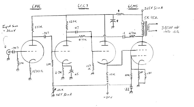
Looking at the circuit now, to start with the output stage, the supply
used was 265V @ 50mA.
The anode voltage should be 240V when the 6CM5 anode is drawing 45mA.
Allowing for the
DC across the speaker transformer, the total supply will be more than
this (hence the 265V in my
circuit). The ideal load impedance is 240/0.045 = 5.3kOhms, but obviously
in the real world
5kOhms will do.
Note that the control-grid and cathode are connected together so there
is no bias; the cathode
resistor is used for a DC stabilisation circuit. The screen-grid voltage
is set by the 6CG7
cathode follower; about 25V is what is required for correct 6CM5 anode
current. Due to such a
low cathode voltage, it is necessary to take the load resistor to a
negative supply otherwise the
waveform becomes clipped on the negative swing. The -30V supply is
not critical at all;
anything more negative than about -20V is adequate.
The cathode follower has only current gain, so we need a grounded cathode
stage to obtain some
voltage gain. This is the purpose of the other half of the 6CG7. The
anode is DC coupled into the
grid of the cathode follower by a voltage divider which sets the 25V
on the cathode. However,
such a divider would also reduce the AC component if it were not for
the 0.47µF capacitor.
The reason for using DC coupling becomes apparent when we see that the
grid of the 6CG7
voltage amplifier is connected to the 6CM5 cathode via an adjustable
voltage divider. This is
where the DC stabilisation comes in. If the 6CM5 should start to draw
more current, the voltage
across the 50 Ohm cathode resistor will rise, making the 6CG7 control
grid more positive. This
in turn makes the anode voltage decrease, thus reducing the DC on the
cathode follower output
and therefore reducing the 6CM5 screen voltage which in turn reduces
anode current.
Notice that adjustment of DC feedback is achieved with a 100kOhm preset
potentiometer.
The way this is connected means that if it should go open circuit (which
is the normal method of
failure of a preset pot), the 6CM5 will be throttled back. The pot
is simply adjusted for a total
current consumption of 50mA, or 45mA for the 6CM5 anode. The bypass
across the preset pot is
optional; it was included to prevent feedback, but in practice it doesn't
have much effect. If
omitted there will be slight negative feedback from the 6CM5 cathode.
I probably won't bother
including it in future amplifiers.
Prior to the 6CG7 stage is a simple voltage amplifier using a 6AV6 triode.
This increases the
sensitivity of the amplifier to 56mVrms or without the cathode bypass
on the first 6CG7 triode, to 100mVrms. Negative feedback is provided in
the shunt form by the 470kOhm resistor, with the 0.1µF used for DC
isolation. Feedback isn't applied to the 6AV6 as it's a triode handling
low
voltage and in my opinion it isn't necessary. That's a matter of personal
preference; in fact I
probably won't include any negative feedback for my first application
of this circuit; that of a car
radio for my Model T Ford. (I ended up using a 6AQ5 in the Model
T car radio, but did use the 6CM5 in my AM/FM
tuner) With the road and engine noise in an open car, Hi-Fi
is scarcely worth trying to attain!
There are points to note regarding construction. Firstly, the 6CM5 cathode
resistors could
obviously be replaced with a single 47 or 56 Ohm 1/2W resistor. Secondly,
if the component or
valve tolerances are so far out that there's not enough adjustment
in the 100kOhm preset, the
150kOhm resistor can be reduced if the current can't be reduced, or
increased if the 6CM5 can't
draw the requisite 45mA.
The components marked * are for decoupling. I didn't need them in my
prototype as a regulated
power supply was being used (a BWD 215) with very low output impedance.
The values aren't
critical, with the resistor being from about 2.2kOhm to 10kOhm and
the capacitor being 8µF or
more.
The 6CM5 could obviously be replaced with a 25E5 if it's convenient
to obtain 25V @ 300mA
for its heater. The 6CG7 is the modern equivalent for 6SN7 so this
valve could be used along
with others in this family such as 12AU7 and 12BH7.
The 6AV6 is really half a 12AX7, but just about anything could be used
for this stage. More gain
could be obtained by bypassing the 6AV6 cathode resistor. And finally,
keep in mind that the
heater current for this amplifier is 2.1A, which is one of the main
disadvantages of using the
6CM5 in the first place.
John Hunter, February/March, 2003
By 1969, every Australian designed valve TV set was using
the 6CM5 line output pentode.
