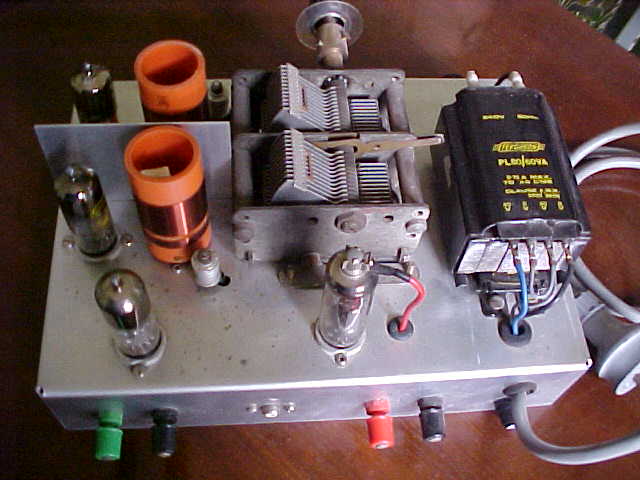
On/Off Volume is at left, with radio/external input switch at right.
On/Off Volume is at left, with radio/external input switch at right.
This set was built back in 1997 to determine
the performance of a TRF set with only one RF amplifier.
I had seen from reading Wireless Weekly
issues from the late 1920's to early 1930's that this was not an unusual
arrangement in good signal areas. Most TRF sets used a three or four gang
tuning condenser, along with the same number of extra valves and coils.
By omitting all but one stage, a much cheaper receiver could be built.
At this point I departed from the 1920's designs by using TV valves and
an infinite impedance detector. As with many of my projects I used TV valves
here because they're common, cheap, and I have a lifetime supply of them.
The power supply was also novel, using
a modern power transformer I had on hand.
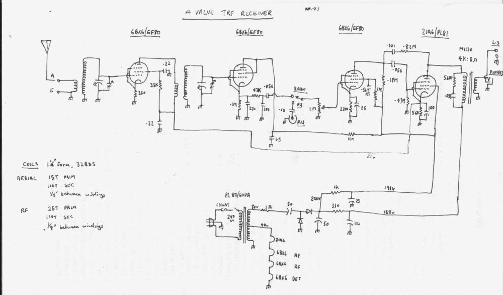
RF Amplifier
A conventional tuned circuit formed by
the aerial coil and one gang of the tuning condenser feeds the input of
the RF amplifier valve in the usual way. The valve is a 6BX6, or as Europeans
would know it, EF80. This is an RF pentode developed in the late 1940's
for use in TV IF amplifiers, but like others ended up being used for many
different applications.
As such, it is of fairly high gain. For
a 7Mc/s channel bandwidth, three 6BX6's are required in a typical television
IF stage. It can be imagined that down on 1Mc/s with say 10Kc/s bandwidth,
the gain will be very high indeed. To put things into perspective, the
6BX6/EF80 has a transconductance of 7.4ma/V, whereas a typical RF pentode
normally used in a MW set, such as a 6K7 has a transconductance of 1.5mA/V.
Later valves such as 6BA6 have around 4.4mA/V.
Your eyes might light up at the thought
of replacing the IF and RF valves in your MW sets with TV IF pentodes in
view of this tremendous increase in gain. Imagine all the distant stations
you'd be able to receive! Unfortunately, it doesn't work out this way.
The gain is actually too high and due to stray capacitances and other couplings
you end up with an unstable whistling mess. So, when used for narrow band
RF amplification on medium waves, it is necessary to reduce the gain.
One obvious way to reduce gain is to leave
the cathode resistor unbypassed. However, I still found the gain too high.
By reducing the B+ supplying this stage, stability and good performance
was achieved. It may surprise those who can only understand valves
working at 250V to find the RF stage in this set working at 21V. The gain
is still very high at this voltage, but not so much to cause instability.
Not surprisingly, the 6BX6 is another valve useful for low voltage designs.
The source of 21V was simply taken from
the output valve cathode.
Detector
Back in the 20's and 30's, the detector
would usually be an anode bend type, or if regeneration was added, a grid
leak type. However, I decided to use an infinite impedance detector instead.
This type of detector appeared much later in the scene and was usually
associated with hi-fi receivers due to its very low distortion.
Anode bend detectors are essentially a
sharp cut off pentode biassed almost to cut off. It is connected as a normal
resistance coupled audio amplifier, but with a higher than normal cathode
resistor. Incoming RF will cause the valve to cut off on negative excursions,
and conduct much more heavily on positive excursions. Hence, it detects
AM. This type of detector was standard in TRF and superhet receivers up
until diode detectors took their place in the mid 1930's, when valves such
as 6H6,75, and 6B7 appeared. An advantage of this detector is that it does
not load the circuit feeding it as grid current never flows. This means
good selectivity as the Q of the preceding tuned circuit is not reduced.
It also can handle large signals without overloading. However, it suffers
from distortion as the detector valve is also functioning as an audio amplifier
which has too much negative bias.
Another common detector of the time, which
is even older, is the grid leak circuit. It is still the standard today
with regenerative receivers, and can be used with just about any triode
or pentode valve. Here, the grid and cathode form a diode. The grid leak
condenser and resistor simply form the diode load. Because the plate of
the detector valve is bypassed at RF, only the audio component developed
across the grid-cathode diode is passed on. Such a detector must not be
operated with any negative bias. To do so would desensitise the detector
as the incoming RF voltage would have to overcome the bias voltage before
the diode could conduct. In fact, in many battery circuits, the grid resistor
is actually returned to the positive filament supply to do the opposite
and make the detector more sensitive.
As a grid leak detector operates with
no, or slightly positive bias, it is essential that excessive plate current
cannot flow as the valve will be damaged. Hence, such detectors operate
at only 22.5 or 45V if feeding headphones or audio transformers, or through
a resistor of 100K or more when operating from higher voltages.
While this type of detector has good sensitivity,
it does load the tuned circuit, thus reducing the Q and selectivity. When
used in a regenerative circuit these losses are made up and become irrelevant.
Likewise, in a TRF set with no regeneration, a couple of preceding tuned
stages will improve this. The other disadvantage is that, as the valve
is again also an audio amplifier, it is this time operated with no bias.
So, the signal handling is limited before it starts distorting. Grid leak
detectors are thus best used with weak signals. A few grid leak detector
circuits, such as this
are available elsewhere on this site.
Another kind of detector eliminates the
loading and distortion problem. It is called the "Infinite Impedance Detector".
The grid is never driven positive and thus does not load the tuned circuit,
allowing full selectivity and gain to be obtained. In terms of the audio
signal, it is operating with 100% negative feedback due to the cathode
follower configuration. As can be imagined, audio gain is not as high as
the other types and needs to be made up in successive stages.The type of
valve used is not critical and most triodes can be used.
This kind of detector was often used in
various TRF and wideband superhet circuits throughout the 1940's and 50's
and was used in many Radio & Hobbies circuits. In view of its advantages,
this is the detector I chose for this receiver.
As can be seen, it uses another 6BX6/EF80.
This time the valve is triode connected as it is operating as a cathode
follower. The 100K and 270uuF form the diode load, with additional filtering
by the 47K and 100uuF. A line level signal is available at this point.
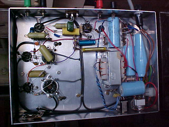
Terminals from left to right are: Aerial, Earth, Speaker. RCA socket
is for external audio input. Note the shielding between the two stages.
Trimmer capacitors adjacent to the coils are for alignment at the top end
of the band. The top cap of the 21A6 is live at about 180V.
Audio Stages
Yet another 6BX6 is used as the first
audio amplifier and is used in the conventional way. I provided an audio
input socket for use with a CD player or FM
converter as an added convenience.
For the output stage, things became unconventional
as I'm using a 21A6 (PL81) line output pentode. This is not a hugely common
valve in Australia as series heater TV sets were in the vast minority.
However, it was used in some Ekco
models and a few others. The 6CJ6 (EL81) which is the 6.3V heater version
was used in a number of Astor models. However, I do have some in my collection,
and as I was tied to using a 300mA series heater circuit, it was a perfect
choice. As I've discussed at length here,
TV line output pentodes generally are a poor choice for single ended audio,
at least when used in conventional circuits. Not all are as bad as the
6CM5/EL36 in this application, and I found the 21A6 to provide a couple
of watts of good quality audio. In view of the heater current, it would
be wasteful to use this circuit on a 6.3V heater supply with the 6CJ6 when
much more efficient audio output valves are available.
The output transformer is an Altronics
M1120 100V line transformer with the 4K primary tapping used. See
here for more details on this.
Negative feedback with a slight amount
of bass boost is achieved by the 820K and .001uF network. The RC network
across the primary of the output transformer is for this particular type
and helps improve frequency response.
Power Supply
I have a number of Ferguson PL80/60VA
transformers available. These are rated at 60VA with two 40V secondaries.
I had often thought about how they would go for powering a valve radio
by connecting the secondaries in series and then following with a voltage
doubling rectifier. For the heaters, they would have to be in a series
circuit powered from 40V. This receiver was the test for this, and it worked
perfectly.
As it happened, I didn't need a dropping
resistor as all the heater voltages added up to 40. It is because of the
6BX6's that the heater current had to be 300mA. This meant the output valve
also had to be 300mA and was one reason I chose the 21A6. I could have
used a 16A8/PCL82 with a dropping resistor instead. Note the order in which
the heaters are connected. It is important to have the valves more susceptible
to hum at the earthy end of the heater string. While I could have used
a full wave voltage doubler, it would have meant the whole heater chain
floating at about 90V above earth which is not a good thing.
Once again, we see just how easy it is
to use valves with modern transformers.
As with some of my other MW receivers, I've made the coil formers
to plug into octal sockets. Power supply circuit is to the right, RF to
the left, and audio at the top.
Performance
Sensitivity is surprising given there's
only one RF stage. I can easily get 2LT from Lithgow and 2BS from Bathurst
in the day time, even though their signals are directed away from where
I live. All Sydney stations come in with good strength and there are no
problems with selectivity. At night, the usual interstate stations are
receivable.
The most notable thing is the excellent
sound quality. As I have said elsewhere, if people heard low distortion,
wideband AM, they would not tolerate the $5 squawk boxes with their nasty
2Kc/s bandwidth, class B output stages, and 2" speakers. Neither would
they hold the view that FM is essential for music listening.
Triode RF Amplifier. (July 2014)
Many "radio people" have an aversion to
TV valves, and throw them away. When building a TRF set, they'd use
some low gain pentode, like a 6J7 or maybe a 58. As a TV enthusiast, I
know the virtues of these unwanted valves, and as can be seen throughout
the site they are good for all purposes.
In view of the huge amount of twin triode
VHF amplifier valves I have, it seemed worthwhile to see how they would
perform as a medium wave RF amplifier. Now, triodes are not new for this
purpose. Triodes were all that were available until the late 1920's. To
use them as an RF amplifier is complicated by the grid to plate capacitance
which can cause oscillation.
At the time, one way out of the problem
was to use the Neutrodyne circuit, or if you didn't want to pay Hazeltine
patent royalties, resistors in series with the valve grids would stabilise
the circuit. Despite this, triodes are less noisy than screen grid or pentode
valves. By the mid 1950's, TV tuners were using triodes because of their
improved noise characteristics. The first method was to connect two triodes
in 'cascode' style in order to overcome the stability problem. Typical
valves for this service are 6CW7, 6BQ7, 6ES8. Then, in the early 1960's,
the neutralised triode method became popular. The most common of type used
in this circuit is the 6GK5.
The four valve TRF set described here seemed
to be the ideal test for the concept. I chose a 6ES8/ECC189; this being
a very common frame grid valve. The circuit was made up as follows:
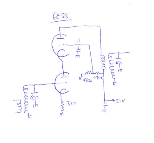
Essentially, the 6BX6 was substituted directly
with a 6ES8 cascode circuit, using the same bias resistor and supply voltage.
In fact, I simply made an adaptor that plugged into the 6BX6 socket with
the 6ES8 and circutry built onto it.
As can be seen, it is a standard cascode
circuit. The lower triode is biassed in the usual way with a 330R resistor.
Normally, this would be of lower value, and would be bypassed, but in this
receiver, excessive gain causes instability. The upper triode is biassed
in the usual way to about half the supply voltage. The upper triode functions
as a grounded grid amplifier and thus provides the isolation between the
two tuned circuits. With a tetrode or pentode, the screen grid provides
the isolation.
More astute readers will wonder about
the heater current and the series heater circuit this receiver uses. The
6ES8 requires 365mA at 6.3V. This means in a 300mA series heater circuit,
the 6ES8 will be slightly under run, and the other valves very slightly
over run. To correct this, the heaters of the other valves need to be bypassed
with a resistor to increase the heater current by 65mA. Alternatively,
the 300mA series heater version, 7ES8/PCC189 can be used.
Improved Performance.
The circuit worked extremely well with
the 6ES8. In fact, 2ZB from Wellington, NZ, was received at room filling
volume the first night I tried the new RF amplifier. The gain is higher
than the 6BX6. I also noted that gain across the band seemed to be more
even. As with the 6BX6, full B+ cannot be used because of instability.
No doubt, if the coils were shielded or perhaps mounted at right angles
to each other one could raise the voltage. However, it does illustrate
that, again, many normal valves work well at low voltage.
Having proven the concept, it opens possibilities
for new designs. For example, a high gain, low noise all triode TRF receiver
without having to use the Neutrodyne approach. This will be on the list
of future projects.
Other valve types.
There is a wide choice of valve types
that could be used apart from the 6ES8/ECC189. Types such as 6DJ8/ECC88,
6AQ8/ECC85, 6FC7/ECC89, 6CW7/ECC84, 6BQ7, 6BK7, etc., and their series
heater variants. The older 12AT7/ECC81 should work but will probably require
higher B+. Note that none of these other types has actually been tested
and some experimenting may be required. The 6ES8 is the highest gain with
its frame grid construction. As mentioned before, modifications may need
to be done to the heater supply if this receiver is built with a series
heater circuit. European constructors will find the PCC189 easier to get
than the ECC189, and this requires no changes to the heater string.