Ekco TX287
by John Hunter, Nov. 2002
|
Amongst first generation models, certainly in
Sydney, sets like the Ekco TX287 were much better known than the
Melbourne-made Astors abundant further south. The Ekco was significant
in that it was a live chassis model, with the valve heaters connected in
series. That was quite against convention in Australia. It's almost certain
that most technicians you mention this set to will say how much they hated
it, as a result.
Introduction
I've always liked unusual designs. That's why I was so keen for years
to find an Ekco, and now that I actually have one and have restored it,
I like it even more. It turned out to be very easy to work on with excellent
service access. Quite different in my opinion to the set that most TV technicians
hate. |
| Let's talk about the points of interest specific to this particular
set, rather than describe the circuit technically. I've restored an example
of this Ekco model, and here I describe how I went about doing so. Obviously
as I touch on each part of the set it's unavoidable to help make you familiar
with its technical aspects, but I try to do so without doing the "how a
TV set works" routine.
Amongst the several companies, both well-established already or new,
tooling-up in Australia for the start of TV in 1956, was Ekco. This was
a pedigreed British radio and TV company, named after E.K. Cole, it's founder.
The Ekco TV sets of the 1950's were of interest to me because of the
power supply arrangement, which although of standard British design, was
relatively rare in Australia. The transformerless technique was used, where
all the valve heaters were connected in series to operate directly from
the mains, and the B+ supply also came directly from the mains via a rectifier. |
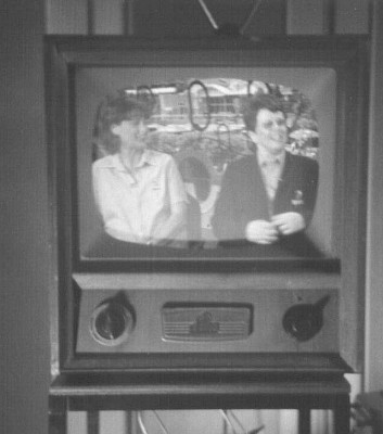
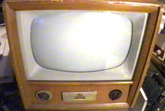
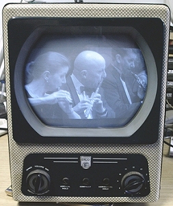
The restored and working Ekco model TX-287. |
 |
One side of the mains was connected to the chassis, possibly making
it "live", at 240V, depending on the mains polarity!
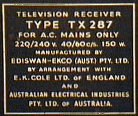
In Australia, Ekco formed a partnership with AEI (Australian Electrical
Industries) and manufactured under license from another British company,
Ediswan. Ediswan was a partnership of the Edison company of the US and
Joseph Swan of the UK. (The first successful incandescent light bulb was
developed by Joseph Swan shortly before Edison's success - despite what
popular [and US influenced] history tells us). |
Finding an Ekco
I'd first heard of these Ekco sets through the "Serviceman" columns
of "Radio, Television and Hobbies". (This was former title of "Electronics
Australia"), and became keen to acquire one. Years went by before one turned
up after I'd put the word out amongst colleagues within the HRSA (Historical
Radio Society of Australia). So, it was at the September 2000 meeting at
one of the member's homes in Goulburn, that a 17" Ekco TX287 from 1957
was offloaded into my hands together with the terse remark "I hate the
thing . . . take it away!"
 |
Downloads
The following download(s) are available; click in the links below. You
first need WinZip to extract each file once downloaded, then Adobe Acrobat
to read it. Both WinZip and Acrobat Reader are readily available on the
'net.
|
Unfortunately, the first sight of the set was a bit of a disappointment.
The phosphor was blown off the screen. Obviously the CRT had been broken.
Also, there was no channel knob or connector for the mains input. At least
the cabinet was intact, with the veneer in acceptable appearance.
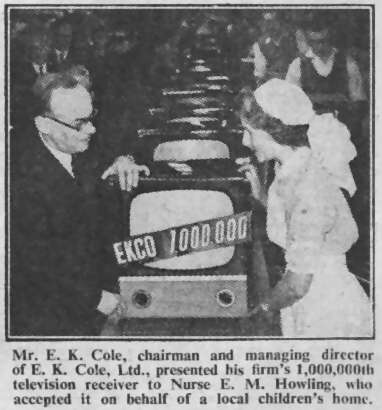
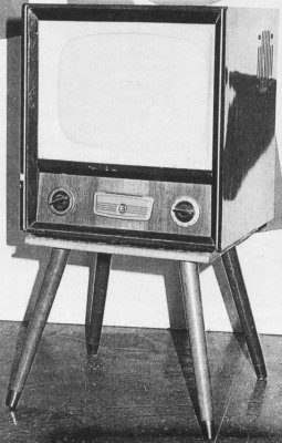
This picture is from Practical Television, March 1958.
It illustrates something of Ekco's background in the UK; Ekco was a very
large company there unlike in Australia where it only existed for about
5 years. |
How the set got to Goulburn is a mystery. For one thing there was a
Service Card inside the set from the 1960's indicating it had been repaired
in West Ryde (a Sydney suburb). The Ekco was not fitted with the channels
used in Goulburn. Why the CRT was deliberately broken at the neck is also
unknown. It appeared that a screwdriver had been pushed under the tube
base to break the exhaust tip.
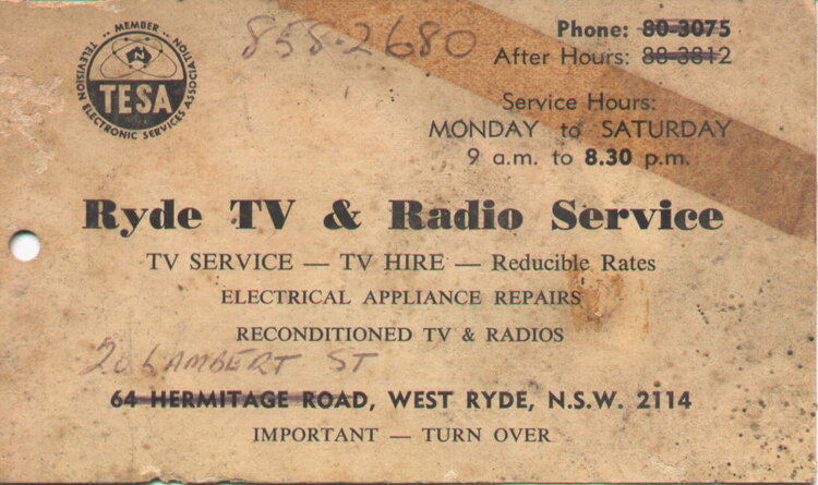
At some point in its life, my TX287 had been here.
So, until I found a CRT not much could be done. I did sort out the mains
lead as I'd kept one off another 21" Ekco chassis I had found elsewhere.
The mains connection is to a two-pin polarised connector sticking out from
the chassis. This arrangement, typical at the time but not seen today,
was intended as a safety feature. The idea is that you can't take the back
off the set without disconnecting the mains supply. However, someone's
interim method of connection consisted of some figure eight flex soldered
to the protruding pins and wrapped with tape! Rough!
Later, another TX287 chassis appeared and it had a channel knob, albeit
with no channel number ring. At least I could change channels, and not
be at risk of electric shock. |
Broken Picture Tube
Since the time I'd acquired the set, the CRT was the major problem.
Last of the major new and reconditioned tube suppliers "Thomas Electronics"
had not been making TV CRT's for about ten years, and no other rebuilders
still existed. I searched the Internet only to find that had I been in
the UK or US I would have had a chance. I enquired amongst any TV tech
sort of person I knew of and still no luck. I wasn't specifically after
the same CRT used in the Ekco; any 17" 700 tube would have got
me out of trouble, as the bulbs are all physically the same. The original
CRT has a 12.6V 300mA heater to fit in with the series circuit, so in order
to use a tube with the more common 6.3V 600mA rating, I would have to install
a small transformer for the heater, and complete the existing heater circuit
with a 42 Ohm resistor.
Almost exactly a year later I was at a deceased estate garage sale.
Noticing there was some interesting valve era junk in the skip out the
front, I went exploring. I saw what looked like a CRT amongst it all and
pulled it out seeing it was intact. I couldn't believe my luck when I looked
closer and saw it was the exact CRT! Not only that, it had a set of deflection
coils still attached, and further digging in the skip revealed another
TX287 chassis, CRT mask and safety glass! Unfortunately the whereabouts
of the cabinet was unknown. The horrifying revelation was that the persons
who had put all this stuff in the skip had tried to break the CRT. If they
had succeeded, sharp pieces of glass would have flown in all directions
with extremely dangerous consequences, as three tons of air pressure had
it's way. It did occur to me that the glass could have been weakened by
their destructive attempts, but as I couldn't see any scratches it looked
like I'd get away with it not imploding on me.
Restoration could at last commence!
| Overview of the TX287 Design
Now, lets have a look at the set itself as we see what was involved
in bringing it back to life.
The cabinet is the typical plywood veneered and shellacked style popular
at the time, with a plywood back (most other sets used masonite), a flip
up lid at the front under the CRT, hiding some of the least used controls,
and what appears to be plate glass for the implosion screen. The safety
aspects of this would have to be doubtful. Underneath is a removable plywood
panel giving access to most of the components under the chassis. |

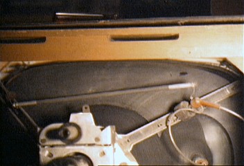
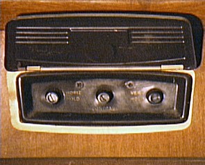
The front section of the TV - at centre is the control
flap. |
| Looking inside the cabinet we see several things unusual from the Australian
perspective.
First thing of course is the big green wire wound resistor used for
the heater dropper, complete with aluminium cowling to direct the heat
out the cabinet back. Towards the front of the chassis is a grey finned
selenium rectifier occupying about a third of the chassis width. On top
of the CRT is a "Metrosil" with one end connected to earth and the other
to the EHT connection on the CRT. A Metrosil is a high voltage VDR (Voltage
Dependent
Resistor)
used to stabilise the EHT, use of which is pretty unique to British designs. |
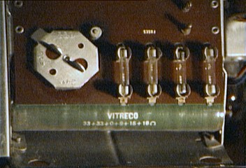
Detail showing the heater dropper resistor. |
| Furthermore, there is a high voltage capacitor connected to the EHT
connection, to smooth the EHT, as this CRT is of old enough design not
to have the metalisation on both sides of the glass, and hence suitable
internal capacitance for doing this job.
As mentioned earlier, there is no power transformer, and the set is
a good deal easier to lift as a result of that. The chassis is also more
compact, and as a result the cabinet has a tall, narrow look compared to
other sets. The chassis itself actually consists of two parts. The tuner,
IF and audio is built on one part, with the deflection and power supply
on the larger half. The two halves are screwed together with a plug and
socket for the electrical connection. |
The Metrosil high voltage VDR, across the back of the
tube. |
One obvious replacement was the line output transformer, but this was
no surprise. The original used by Ekco had a plastic support for the transformer
itself, and the EHT rectifier socket. The problem was the plastic only
lasted a few years before it crystallised and crumbled away.
| Most surviving Ekco's have therefore had the 3rd party,
(i.e. "after-market", non-original manufacturer), "Telecomponents" transformer
fitted. This uses paxolin (what printed circuit boards are made from if
they're not fibreglass) panels to support the transformer and EHT rectifier.
Needless to say, with an obsolete picture tube being used, magnetic
focus is provided, with a plastic knob protruding from the back of the
set for the user to adjust the ring-magnet position.
At this point we should have a look at the electrical design of the
TX287, typical of that found in other Ekco sets. |
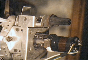
The neck of the CRT, with magnetic focus adjuster visible
at top right. |
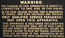
The safety warning printed on the rear cover to alert
the unwary tech! |
The Transformerless Power Supply
Mention "Ekco" to a TV technician of the valve era, and most will reply
with a negative comment, for this was a live chassis set and Australian
technicians were not fond of this sort of design. Ekco thought otherwise,
for their advertisements promoted the advantages of having no power transformer,
such as considerable cost and weight reduction. For the consumer, the sets
worked like any other, and were just as reliable but cheaper. |
A few live chassis sets were produced by other local manufacturers,
but were confined to a few, short-lived portable models. These were made
by Astor and Pope-Motorola. Some of these did include a power transformer,
but it was an autotransformer, the design of which does not provide isolation
between primary and secondary. Pye also had a 21" transformerless model
but it was a short lived one-off design. The last transformerless set in
Australia was the Thorn R2M, which was used as a rental model in the early
1970's. It was based on the British Thorn 1500 chassis. No one else was
manufacturing and selling transformerless sets in the quantities and for
the time period that Ekco did.
There had been transformerless radio receivers made in Australia during
the 1930's and 40's, for the rural areas with DC mains, but this was unavoidable.
Power transformers work by virtue of a constantly changing magnetic field,
so are unsuitable for DC.
Let's look at what this "transformerless" technique is all about. A
valve television receiver requires two supplies. One is the anode and screen
supply. Typically 210-250V DC is required at about 250-300mA. The other
supply is for the valve heaters. For a standard set using a transformer,
this is 6.3V and may require up to about 8A, depending on how many valves
the set has. A 5V winding at 3A is also included if the set uses a 5AS4
or 5U4 rectifier valve.
The B+ comes from a full-wave rectifier, whether it be valve or solid
state, using a centre-tapped transformer winding (for two diodes), or one
single winding with a bridge rectifier (four diodes).
Later practice was to use a 115V secondary feeding a voltage-doubling
rectifier to produce the 250V DC supply. In any case, the transformer makes
for an efficient and safe power supply, as the secondaries are isolated
from the mains, and the chassis can be earthed as in any other electrical
appliance. This is what Australian design engineers and technicians were
used to, and so the large Australian brands like HMV, Kriesler and AWA
continued using the standard transformer power supply when TV became part
of their manufacturing, despite the power transformer being the second
most expensive part of the set.
Ekco's appearance changed that. For this was a UK company and transformerless
designs had become standard there by 1956.
No Transformer
So how does it work? How do we avoid such an expensive, heavy, and seemingly
essential component? The high-tension supply can be obtained by rectifying
the mains supply directly, as it just so happens to provide a suitable
voltage. Half wave rectifiers are used so that the mains neutral is connected
to the chassis, in order to make it safe to work on. Selenium rectifiers
were popular as no heater current is required. Silicon rectifiers of sufficient
voltage rating did not appear until the 1960's.
A conventional pi filter is used in the TX287, made up of C95, L15 and
C96. With half-wave rectification, filtering is more difficult as the filter
capacitors get charged every 20mS instead of every 10mS. So, capacitor
values are generally higher than if a full wave rectifier was used.
Further improvement to filtering can be made by actually resonating
the filter choke at the ripple frequency. This is where C105 comes in.
The resultant DC is approximately the same as the RMS of the mains supply.
Even though the DC output would be close to the mains peak (340V) if no
load were on the supply, it is a lot less under load. This is due to the
voltage drop across the rectifier's surge limiter, R115, the rectifier
itself, MR1, and the choke L15. Different mains voltages are accommodated
for by including a suitable resistance in series with the rectifier input;
R116 and R117.
The heater supply is where things become different. Theoretically, the
transformer could be dispensed with by using a resistor to drop 240V to
run a normal parallel heater circuit operating at 6.3V. Problem is, with
a heater current approaching 8A, the resistance would be dissipating nearly
2,000W! This is obviously unacceptable.
The proper way is to have the valve heaters connected in series. This
way, the heater current will be considerably less and the total voltage
a lot higher than 6.3V, thus minimising the dissipation in the heater dropper
resistor. The same current flows consecutively through all the valve filaments,
and the amplitude of that current is merely that required by any one of
them.
Special Valves Required
In the 1950's, the various European valve makers developed suitable
valves for TV use in series-heater circuits. Regardless of the heater voltage,
the current was standardised at 300mA, and the heaters had a controlled
warm up time. If we look at the heater characteristics of the valves in
the TX287, we can determine that the heater string requires about 180V
at 300mA. For 240V mains, the dropper resistance would be about 200 Ohms
and it would dissipate only 18W. Obviously, the minimum mains supply that
could be used for a set with these valves would be 180V. The Ekco allows
for different mains voltages by selecting the appropriate resistance when
the mains voltage switch is adjusted.
This is all good in theory, but there are a couple of refinements to
improve upon our heater supply.
It is good practice to include a thermistor in series with the heaters.
In the TX287, this is R102.
It is a characteristic of a valve heater to have a much lower resistance
when it is cold, than when at operating temperature. Obviously if the heater
circuit were connected across the mains supply when cold, more than 300mA
would flow through the heaters until they warmed up, possibly shortening
their lives. It is true that the dropper resistor will help limit the current,
but by including a thermistor, extra resistance is included (a few hundred
Ohms) which results in a much lower current flowing. However, with this
current flowing in the thermistor at switch on, it heats up and the resistance
value decreases to just a few Ohms by the time the valves have warmed up.
The valves are thus provided with their correct 300mA current gradually.
The valves are also designed to have equal warm up times. If they didn't,
it is likely that some valves will be subjected to excessive heater voltage
during warm up, more so than others. Slower warm up (and consequently lower
resistance) valve filaments will be dropping less heater voltage, with
the difference being forced across the heaters of the faster warming up
valves.
This was actually a serious problem when series-heater circuits first
appeared in the US during the early 1950's and such sets quickly developed
a reputation for unreliability. The set manufacturers there had tried to
use ordinary parallel type valves in a series circuit. With no controlled
warm up characteristics and heaters designed for constant voltage rather
than constant current operation, valve heaters often burnt out at switch
on.
AC or DC Supply
One of the important advantages of the transformerless design, and one
which was probably responsible for it in the first place, is that an AC
or DC supply can be used. The valves, being indirectly heated, don't care
whether their heaters are fed with AC or DC. When used on DC, the rectifier
merely protects the electrolytic capacitors from reverse polarity. The
polarity of the mains input does become an issue however; reverse "+" and
"-" and there will be no B+.
The Ekco is not rated for DC use. For one thing, the mains switch contacts
are
not DC rated. This means destructive arcing is likely to occur when the
switch is turned off and the contacts separate. With AC, the voltage passes
through zero every 10mS extinguishing any such arc. Secondly, with DC mains,
the maximum voltage the first filter capacitor could charge to is 240V,
not 340V. To restore sufficient B+, the rectifier and possibly one or more
series resistors would have to be shorted out. Sets designed for AC or
DC mains allow for this, usually by connecting a fuse across the rectifier
and any other undesirable (on DC) series resistors. This shorts out the
rectifier, but if the set is accidentally connected to AC, the fuse will
blow, protecting the electrolytic filter capacitors. In simple radio receivers,
the difference between supply voltages when on AC or DC mains is not important,
and this refinement is seldom used.
Shock Hazard
Having so elegantly fed our TV valves with their correct voltages without
a power transformer, there's a catch to all of this. By now it would be
obvious that the chassis of the set is connected to the mains. If it should
be the active side, then a lethal shock could result if it was touched
and the user was earthed. As long as it's the neutral connected to chassis,
there is not a great safety hazard.
It is difficult to guarantee this however. Despite having a polarised
three-pin plug as standard in Australia and NZ, there always remains the
possibility that a non-polarised connector (such as a bayonet light socket,
or extension lead made with figure eight cable) could be used to connect
the set. There was also no guarantee that the active pin on all power points
would be the same, as this was actually not an official standard in the
1950's. (This is also the reason why you see radios and TV's of the era
fitted with double pole mains switches. That was a legal requirement).
In the rest of the world, two pin non-polarised plugs were common, so one
would have to assume the chassis was live anyway. In the UK, one of the
essential items in the TV serviceman's toolkit was a neon screwdriver.
By touching this against the chassis it would indicate whether or not it
was safe to work on. If it should be live, it was necessary to reverse
the mains plug (or the connections thereto if of the three pin type). The
Australian Thorn R2M chassis actually has neon indicators permanently built
in to indicate chassis polarity.
Inefficiency
Another issue is the wasted power across the dropper resistor. Unless
the sum of the heater voltages is the same as the mains supply, a voltage-dropping
resistor is required, and this will dissipate heat that has to be ventilated
out of the cabinet. It is true that the resistor could be avoided by running
the heater string off a transformer, which may as well be the cheaper autotransformer
as isolation isn't required with an already live chassis. However, we get
back to having a weighty and expensive part. Another method is to use a
capacitor to drop the voltage, using the capacitive reactance. No power
is dissipated, but there is a risk of breakdown, exposing the heater string
to full mains voltage. A later method was to include a diode in series
with the heaters. As the diode only conducts on every half cycle, we automatically
lose half power. The resulting RMS voltage is about 170, so this method
is restricted to use with heater strings of equal to this voltage (or lower
with a resistor still required). These three methods have been in fact
used quite frequently, with the capacitor method the least popular. However,
only AC mains can be used.
User Safety
The most vital aspect of using a live chassis is to insulate it from
the user(s). In the TX287, the chassis mounting screws are insulated by
nylon bushings and aren't accessible from outside the cabinet. Although
the loudspeaker mounting screws are exposed, the speaker itself is isolated
by the audio output transformer, (T4), which has stringent insulation requirements.
As the speaker could acquire a static charge (given the proximity to the
CRT), and thus give someone a mild, though harmless shock, a high value
resistor is connected from the chassis to the speaker frame. This is R34
(1MOhm). Not more than 240µA could flow if the user touched the speaker
while the chassis was live. This sort of current can't normally be felt
and is quite safe.
 |
|
 |
The aerial connection also needs care in its design. By using low value
capacitors in series with each aerial lead, the VHF signal can pass through
with minimal loss. But at 50Hz, a 470pF capacitor has a reactance of about
680kOhms. Again the current that could flow is not dangerous. Across the
aerial isolation capacitors (C1 and C2) are resistors (R1 and R2). These
are needed to discharge the static that might build up on the aerial. With
no DC path to earth, the static voltage could build up until the capacitors
breakdown voltage was exceeded. This would cause interference on the picture,
let alone compromise the reliability of the capacitors. Again the static
discharge resistors are high enough for safety.
At the front of the set, the knobs are plastic and do not have any exposed
metal parts. Likewise, the preset controls at the rear also have plastic
shafts. The back of the set is enclosed so no part can be touched inside,
and as previously mentioned, the back cannot be removed without disconnecting
the mains supply.
After all this, such a set might be considered safe. In normal use it
is, but there have been electrocutions from radios and TV sets with a live
chassis. Simple component failure can cause the aerial to become live,
in the case of C1 or C2 going short circuit. More common though, is improper
servicing and alterations of such sets, which still occurs to this day
with modern solid state colour sets.
A common practice is to connect headphones or a tape recorder to the
audio system by a non-technical person. The results of this can be imagined
if the user, or externally connected devices, should come into contact
with something earthed.
Incorrect servicing resulted in at least one death in the UK. A speaker
mounting screw had been replaced with one longer than the original. It
pierced the cabinet front and made contact with the speaker grill cloth
that had metallic thread woven through it. A young boy touched the speaker
cloth while the set was on and was electrocuted.
Aerial bypass capacitors are sometimes ignored when the aerial terminals
or socket fails, and someone replaces the socket/terminals connecting them
directly to the ribbon or coax leading to the (live at 240V) tuner.
Unpopular with Supply Authorities
Apart from the safety aspects, there was one thing that did make the
electricity supply authorities in Australia unhappy. With a half wave rectifier,
the result was asymmetrical loading of the mains; i.e. DC was being put
on the mains by sets such as the Ekco. This can result in various forms
of corrosion in the supply as well as saturating step-down transformers.
With the few such sets in Australia it is doubtful that it would ever
have been a problem, but it seems they weren't so convinced in Victoria.
In this State, the TX287 was actually the TX287V. To avoid the DC problem,
the heaters were fed from DC in opposite polarity to the B+ supply, so
largely cancelling out the DC component. A separate selenium rectifier
is used for the heaters (MR2). With the heater string taking 300mA of negative
DC, and the B+ taking about 250mA of positive DC, the result would be about
50mA of DC put onto the power mains which is a lot less than when AC is
used for the heaters.
Because of this DC problem, all modern live chassis sets use a full
wave rectifier. This does however mean the chassis is live at all times
regardless of mains polarity. It is essential to use an isolating transformer
when working on these sets.
 |
Other Design Features of the TX287
The rest of the set isn't particularly unusual, so it is not intended
to give a detailed description of it here. The components used are a mixture
of Australian and British. The CRT was made in the UK, as were the resistors
and some of the capacitors. The turret tuner was never fitted with coil
biscuits for all 10 Channels. Fortunately, the present capital city Channels
were amongst those fitted. |
The IF-strip is standard, except that there's been a simplification
by using IF transformers with one winding. With only three stages of video
IF amplification the gain can't be expected to be as good as a set with
separate primary and secondary windings, and this suspicion was actually
confirmed, in practical use.
Gated AGC is used, with the contrast control operating in this part
of the circuit rather than in the video amplifier.
In the sound channel the only point of interest is the use of a PABC80
valve. This was rarely seen here, although standard in Europe. The RMA
number is 9AK8 with the parallel heater version being 6AK8 or EABC80. This
valve combines the ratio detector diodes with a triode, forming the first
audio amplifier stage.
| Both line and frame oscillators use the blocking oscillator circuit,
which is again nothing new. But getting to the line output, things start
to get a bit more interesting. A PL81/21A6 is used. This was unique in
that it was the only 9-pin line output valve to have existed. The parallel
heater version is EL81/6CJ6.
Interestingly the EHT rectifier has a 6.3V heater. It's an EY82 or 6S2.
For the Telecomponents line output transformer fitted to my set, the more
common 1S2/DY86 had been preferred.
The other two components here of interest are C97, a 1000pF 20kV capacitor
and the Metrosil R104. Just as in any other rectifier circuit, the EHT
needs to be filtered to produce pure DC. Since the 1950's, this has been
automatically achieved by the metalisation on both sides of the CRT glass,
which acts as a capacitor. The CRT (CRM171) is an old tetrode design and
does not include this feature. It would have had its origins well before
Australia set up for TV.
The EHT is regulated with a voltage dependent resistor, with the trade
name of "Metrosil". The function of this component is to drop its resistance
as the applied voltage increases. In its function as a shunt regulator
here, it can be imagined that if the EHT rises, the resistance will decrease,
drawing more EHT current and thus reducing the voltage again. |
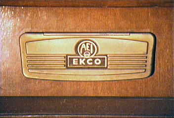
Another slightly different TX-287 from c.1956~7, with
an alternate logo on the front flap. |
Obviously set designers outside the UK didn't seem to think EHT regulation
needed to be so accurate . . . but then in the heyday of the earlier 405
line era most uk manufacturers had attended well to the finer points of
set design.
CRT Replacement
The first thing to do was to replace the CRT to see what sort of condition
my newly acquired replacement was in. First problem was to get the knobs
off. With no grub screws one would think they are held with spring clips...but
after finding them awfully tight, the truth was revealed when I had a look
at one of the TX287 chassis with knobs still on it. Well, there were grub
screws, but inside the cabinet! It soon became apparent that the knobs
were to be left on the chassis as it was withdrawn, having first removed
the clip on plastic rings around the knobs. I could now see why the knobs
are often broken with this model. If I'd had the Service Manual at this
stage I would have already known this.
Once I'd learned the secret of chassis removal, it was becoming apparent
that this set had excellent service access. Only three small screws needed
to be removed and the chassis could be slid out the back of the cabinet
and conveniently stood on its side.
Swapping over the CRT's was straightforward, but it is not a job I'm
fond of doing; for in my hands is a glass vessel which could be lethal
should it implode. Having witnessed the implosion of a 21" 90 degree tube,
I'm well aware of the extreme dangers in handling picture tubes.
Upon reconnecting the chassis, turning on the set, and adjusting the
ion trap, I was pleased to get a nice bright and perfectly focused raster.
The tube was perfect!
It was also evident that the selenium rectifier was OK with normal B+.
This was the first set I've had with such a rectifier fitted. So I wasn't
familiar with their reliability, although I'd heard they seemed to fail
occasionally in the UK TV service literature I'd read. Had the rectifier
been weak, I would have connected across it a silicon diode, with a series
resistor to compensate for its much lower forward voltage drop.
A quick look for apparent fault symptoms revealed a very critical frame
hold control, no sound, and rather poor front-end gain. All of the channels
needed the local oscillator adjusted. Needless to say the line output stage
started to die as the paper boost capacitor started to break down within
a few minutes, but that was to be expected. These were all typical faults,
expected with a valve set full of high resistors and paper capacitors.
Restoration
Restoration started out with the usual routine of replacing resistors
and capacitors. Experience has taught me that resistors over 100kOhms should
be replaced whether or not they test okay as it is these higher values
that tend to drift high. While they might test okay now cold with the chassis
out of the set, they could be responsible for strange thermal faults. Most
of the resistors in this set are actually of British origin.
Virtually all the paper capacitors were replaced, as these are the most
unreliable components known to mankind. It was not valves that were unreliable
in these sets; it was the paper capacitors. These were a combination of
locally produced "Ducon", and British "TCC" and "Hunts". As one colleague
suggested, the latter name is actually the misspelling of a rhyming word,
for all their reliability. I'd agree with that, for they are of the moulded
plastic type. What happens is the plastic cracks, letting moisture in and
causing leakage. The waxed dipped capacitors appear to be better sealed
by comparison. I use polyester capacitors for replacement, with 400V or
630V types in B+, anode and screen circuits, and 100V types for lower voltage
sections like AGC and cathode bypasses.
The only paper capacitors I left were the wax dipped ones, in situations
where leakage is not a problem. For example, C105 across the filter choke.
Experience has shown that electrolytic and ceramic capacitors are usually
OK, so none of these were replaced.
Good Serviceability
One thing that did make component replacement in the Ekco a joy, was
the method of component connection. Vertical posts secured to the chassis
by nylon insulators are used with the component leads wrapped around and
soldered. Simply by melting the solder can the leads be slid off. This
makes a nice change from certain sets using tag strips where the component
leads have been wrapped through the tag 27 times (is anyone from Kriesler
reading this?).
Finally, I cleaned all the tuner contacts with CRC.
After turning the set on, running it from a 500W isolating transformer,
it was evident that more work was required. At the correct setting of the
frame hold control, the picture was on the verge of frame collapse. It
appeared that the hold pot has a very noisy spot on the carbon track. There
was still no sound, and I had yet to adjust the oscillator slugs in the
tuner biscuits.
Missing Resistors
Turning to the sound problem, I had noticed earlier on that the output
transformer had a burnt primary winding. This was odd, for a considerable
current would have to flow to cause this sort of damage. Measuring continuity
showed it was indeed open-circuit ("o/c"). I replaced it with the transformer
from the other spare TX287 chassis, but no sound. Checking for B+ in the
audio section showed none. Tracing though the circuit revealed that R121
and R39 were not there! I'd noticed these 'extra' resistors on the donor
chassis but didn't think too much about it. Upon replacing these two audio
B+ supply decoupling resistors I was getting somewhere, as the PL82 audio
output valve started flashing over in a purple haze. It was obviously suffering
from being gassy, and this was confirmed with my AVO valve tester.
Again, the donor chassis provided another PL82 which was OK. Getting
better, except now R121 was overheating. Still too much current drain.
Normally, leakage of C56, the PL82 grid coupler would cause this, but it
was a new polyester capacitor. Much to my surprise, I found that R47, the
270 Ohm cathode bias resistor had dropped in value. Having repaired valve
televisions for about 20 years, this is the first time I have ever seen
this happen. I had heard about it being common with sets in the UK, but
never seen it with locally made resistors.
The resistor was a reduced fraction of its correct value so there was
insufficient reverse bias, causing the PL82 to draw excessive current.
It would seem that this audio fault was the last fault the set had before
it was taken out of service. The cathode resistor probably reduced value
first, overloading the PL82 and the output transformer. As a by-product
of this, R121 would have burnt up. For some reason, the serviceman only
got as far as removing the charred 330 Ohm resistor and going no further.
Having replaced the bias resistor, I had sound and normal current consumption.
Vertical Hold Pot
The annoying vertical hold was the next point of call. By ever so delicately
adjusting the control, one could get a locked picture, but not for long.
Clearly the pot, VR4, was badly worn. My previous attempt at squirting
with CRC didn't fix it, so it looked like other measures would have to
be used. I checked my two other Ekco chassis for possible replacements.
Looks like the vertical hold pot was the other weakness of this set besides
the line output transformer, for the other 17" chassis had the outer connections
transposed on it's original pot. The 21" chassis had the pot replaced,
but not with the right one. The pot should have a plastic shaft, but this
one was a locally made pot with a brass shaft! Whoever replaced it had
attempted to cover the shaft with a plastic sleeve, but left the end exposed.
Yet another person oblivious to the methods of servicing live chassis sets.
What to do? The problem was the pot was a British type and not something
I'd find easily here. I decided to take the easy way out and reverse the
outer connections, so that the wiper would be on a less worn part of the
track. Although the control worked in reverse, this was unimportant as
it was seldom used. So, now the set had stable vertical deflection.
I had noticed that the horizontal stability was rather poor by now,
but put this down to the front-end not yet working properly causing sync
pulse distortion.
Next job on the agenda was to tune in all the channels properly. Squirting
CRC into the local oscillator coils allowed easy adjustment of the brass
cores, so now all channels were in tune with the fine-tuning control in
mid position. Unfortunately, the gain was still very poor with a very washed
out picture, so I set about tracking that down.
Poor Front-end Gain
First thing was to replace all the likely resistors and capacitors in
the tuner, which I hadn't done with the chassis restoration. This didn't
do anything useful so I began to suspect the tuner valves.
There was some improvement borrowing the valves from the other spare
chassis, but still the gain wasn't what it should be. I went through the
video amplifier stage (V6) and measured the IF strip voltages but still
came up with nothing conclusive. The contrast was still weak.
I decided I'd finally test all the valves. It takes a lot for me to
be convinced to do that, for it is very rare that valves are faulty, except
for the notorious 6AL3, which tends to crack around its base. As it turned
out, not only were both the RF and converter valves (V1 and V2) weak, but
so were the ones I borrowed from the other chassis. No wonder I was mislead!
The only definite way to clear this up was to install new valves. I
ordered a new 7AN7 (PCC84) and 9A8 (PCF80) from Rockby Electronics in Melbourne,
and at last the set provided a picture with decent contrast.
Although I did have these valves in my collection already, my policy
is to buy new valves where possible. This way, if and when valves become
unavailable in the future, that will be the time to draw on my collection.
The set was almost finished, except for one thing; that horizontal instability.
It seemed to vary with video content, so naturally I checked the sync pulses
from the demodulated video signal and at the anode of the sync separator
(V12). All was well here, but it was now becoming apparent that it was
more of an AFC problem, as the fault was far more prominent with the brightness
control turned up. The increase in EHT current and the loading on the line
output transformer must be causing something to happen with the feedback
pulses to the AFC circuit. On bright pictures, there would be severe pulling
to the left at the top of the picture; similar to the problem experienced
with VCR's on certain colour sets.
I did find that someone had replaced V14 (the line oscillator) with
a 12AT7 (maybe to cover up a fault) but replacing with the correct 12AU7
made no improvement. All the component checks revealed nothing faulty.
This was becoming quite bizarre.
Fault Found
Surely, Ekco would not release a set into the public with this sort
of picture pulling. I had a talk to one of my colleagues who knew the set
from his servicing days. Yes, it did have a picture pulling problem worse
than other sets, and that was an accepted part of its design. But it wasn't
meant to be as bad as I had it.
Again I looked over the circuit and all the new parts. Perhaps I'd connected
a replacement part on to the wrong point. I've done that before and it's
easy to do when doing a blanket replacement of parts.
Something didn't feel right when I got to C76 . . . it shouldn't have
been labelled "223" . . . it should have been "222". Bingo! I had mistakenly
put a 0.022µF where 0.0022µF should have been. I'd made the
AFC time constant way too long! Restoring the correct value at last put
the set into working condition.
The last thing to do was touch up the local oscillator cores again as
the CRC had by now evaporated from them. I also retuned the Channel 1 oscillator
core to be on the present day Channel 0 for use with AV gear such as VCR's
and satellite receivers. Normally I use Channel 3 for this, but even though
Channel 3 in the old 10-channel allocation is the same as that now, the
biscuit was not fitted.
No further faults have become evident over the last year, since I got
the unit up and running.
| Dying Days
It would appear that Ekco became aware of the reputation about their
power supply used in their 17" and 21" sets, as they started using a conventional
transformer power supply at the same time as they changed to 1100
deflection early in the 1960's. Soon after, the company disappeared from
the local Australian scene. Apart from deflection components made by the
likes of Rola and Telecomponents, there was no longer any back up for the
uniquely Ekco parts.
Their unpopular reputation then and now is unfortunate, for having restored
my TX287, I've learnt that it is actually quite a good set. The service
access is excellent with easy chassis extraction. In fact for most servicing,
this isn't even required, as the plywood panel under the cabinet can be
removed giving access to most parts. Any ideas this was a 'cheap' set in
view of its transformerless approach are false. Here we have negative feedback
in the audio amplifier, gated AGC, DC coupling to the CRT, EHT regulation,
and exceptional focus and brightness. Many other companies made sets without
any of these features, some being absolutely ghastly as far as service
access goes. But they did have the all important power transformer to calm
the Australian technician. |
Another early made-in-England Ekco model in Australia,
the TX-275 portable. Although isolated rather than live chassis, the use
of magnetic focus in this, and sister set, the TX-276, dates this set to
the late 1950's. There remain quite a number of examples of these small
units extant.
Pic courtesy Leigh Moore.
|
I found the 'dangers of servicing a live chassis' completely irrelevant
during my work on this set, for having it plugged into an isolating transformer
made it as safe as any other.
These days the most common reminder that the company ever existed here
is a popular mantel radio from about the same era as the TX287 TV.
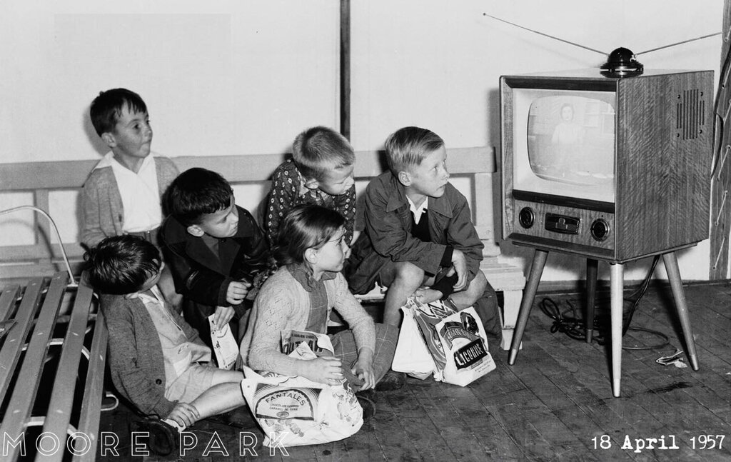
An Ekco TX287 entertaining young viewers at the 1957 Sydney Royal
Easter Show. The position of the channel knob suggests they were watching
Channel 9.
HOMEPAGE

References and Further Reading
(1) Brief
Ekco company history